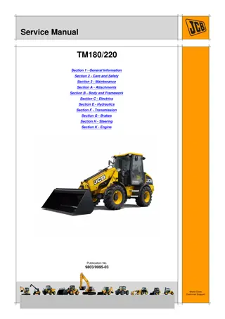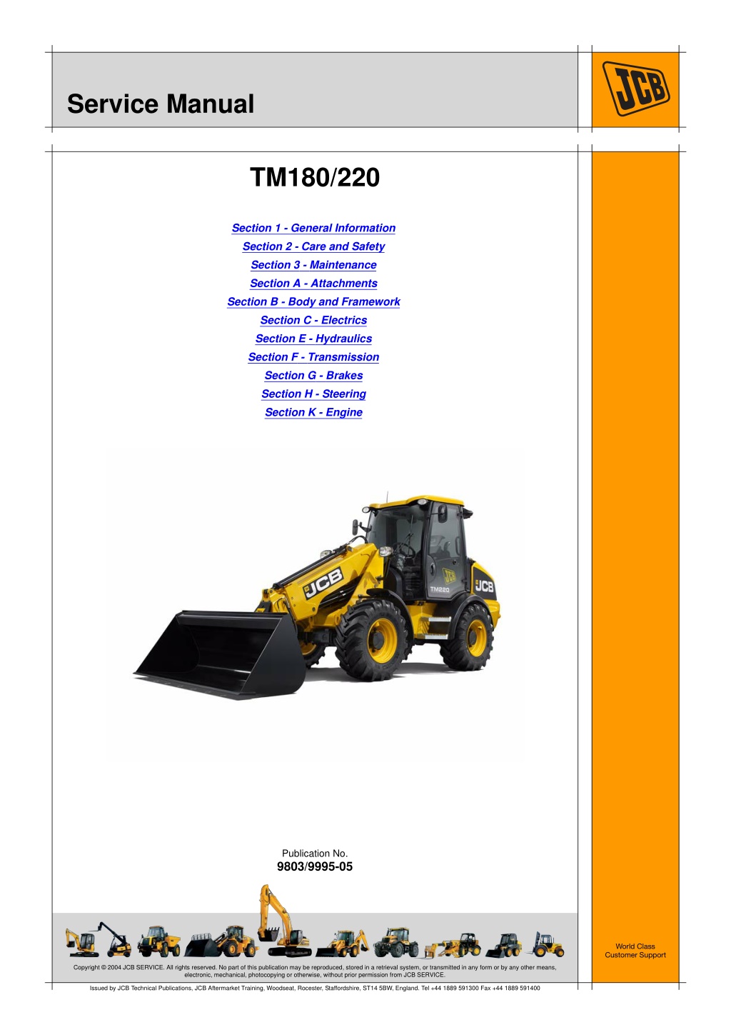
JCB TM180, TM220 [Engine Deutz] Telescopic Wheeled Loader Service Repair Manual Instant Download
Please open the website below to get the complete manualnn//
Download Presentation

Please find below an Image/Link to download the presentation.
The content on the website is provided AS IS for your information and personal use only. It may not be sold, licensed, or shared on other websites without obtaining consent from the author. Download presentation by click this link. If you encounter any issues during the download, it is possible that the publisher has removed the file from their server.
E N D
Presentation Transcript
Service Manual TM180/220 Section 1 - General Information Section 2 - Care and Safety Section 3 - Maintenance Section A - Attachments Section B - Body and Framework Section C - Electrics Section E - Hydraulics Section F - Transmission Section G - Brakes Section H - Steering Section K - Engine Publication No. 9803/9995-05 World Class Customer Support Copyright 2004 JCB SERVICE. All rights reserved. No part of this publication may be reproduced, stored in a retrieval system, or transmitted in any form or by any other means, electronic, mechanical, photocopying or otherwise, without prior permission from JCB SERVICE. Issued by JCB Technical Publications, JCB Aftermarket Training, Woodseat, Rocester, Staffordshire, ST14 5BW, England. Tel +44 1889 591300 Fax +44 1889 591400
Section 1 General Information Service Manual - TM180/220 Section 1 - General Information Section 2 - Care and Safety Section 3 - Maintenance Section A - Attachments Section B - Body and Framework Section C - Electrics Section E - Hydraulics Section F - Transmission Section G - Brakes Section H - Steering Section K - Engine Publication No. 9803/9995-02 World Class Customer Support Copyright 2004 JCB SERVICE. All rights reserved. No part of this publication may be reproduced, stored in a retrieval system, or transmitted in any form or by any other means, electronic, mechanical, photocopying or otherwise, without prior permission from JCB SERVICE. Issued by JCB Technical Publications, JCB Aftermarket Training, Woodseat, Rocester, Staffordshire, ST14 5BW, England. Tel +44 1889 591300 Fax +44 1889 591400
Section 1 - General Information Contents Use Introduction ............................................................................................. 1-1-1 Scope ..................................................................................................... 1-1-2 Personnel ...........................................................................................1-1-2 Applications ........................................................................................1-1-2 Newest Data .......................................................................................1-1-2 Format .................................................................................................... 1-1-3 Left and Right Sides ............................................................................... 1-1-4 Hydraulic Schematic Codes ................................................................... 1-1-5 Colour Codes .....................................................................................1-1-5 Electrical Device Codes .......................................................................... 1-1-6 Page No. Machine Identification Introduction ............................................................................................. 1-2-7 Related Topics ........................................................................................ 1-2-8 Machine Identification Plate .................................................................... 1-2-9 Typical Product Identification Number (PIN) ......................................1-2-9 Component Identification Plates ........................................................... 1-2-12 Typical Engine Identification Number ...............................................1-2-12 Typical Transmission Identification Plate ..........................................1-2-12 Typical Axle Identification Plates - TM180 Machines .......................1-2-13 Typical Axle Identification Plates - TM220 Machines .......................1-2-14 FOPS Data Plate ..............................................................................1-2-15 ROPS Data Plate .............................................................................1-2-15 Torque Settings Introduction ........................................................................................... 1-3-17 Zinc Plated Fasteners and Dacromet Fasteners .................................. 1-3-18 Introduction .......................................................................................1-3-18 Bolts and Screws ..............................................................................1-3-18 Hydraulic Connections .......................................................................... 1-3-22 'O' Ring Face Seal System ...............................................................1-3-22 'Torque Stop' Hose System ..............................................................1-3-25 `Positional Type' Hydraulic Adaptors .................................................... 1-3-26 Fitting Procedure ..............................................................................1-3-26 Service Tools Introduction ........................................................................................... 1-4-27 Numerical List ....................................................................................... 1-4-28 Tool Detail Reference ........................................................................... 1-4-31 Rivet Nuts ............................................................................................. 1-4-50 Fitting Procedure ..............................................................................1-4-51 Slide Hammer Kit .................................................................................. 1-4-52 Fitting Procedure ..............................................................................1-4-52 Service Consumables Introduction ........................................................................................... 1-5-53 Sealing and Retaining Compounds ...................................................... 1-5-54 Fuel Introduction ........................................................................................... 1-6-55 Related Topics ...................................................................................... 1-6-56 1-i 1-i
https://www.ebooklibonline.com Hello dear friend! Thank you very much for reading. Enter the link into your browser. The full manual is available for immediate download. https://www.ebooklibonline.com
Section 1 - General Information Contents Contents Acceptable and Unacceptable Fuels .................................................... 1-6-57 Additives ...........................................................................................1-6-58 Service Requirements for use of B20 Biodiesel ...............................1-6-58 Warranty ...........................................................................................1-6-58 Fuel Types ........................................................................................1-6-59 Usage and Effects of Fuels ..............................................................1-6-60 Sulphur Content ...............................................................................1-6-61 Effects of Fuel Contaminates ...........................................................1-6-62 Page No. Applications Introduction ........................................................................................... 1-7-63 Tables ................................................................................................... 1-7-64 Section 1 - General Information .......................................................1-7-64 Section 2 - Care and Safety .............................................................1-7-64 Section 3 - Routine Maintenance .....................................................1-7-65 Section B - Body and Framework .....................................................1-7-66 Section C - Electrics .........................................................................1-7-67 Section E - Hydraulics ......................................................................1-7-68 Section F - Transmission ..................................................................1-7-70 Section G - Brakes ...........................................................................1-7-71 Section H - Steering .........................................................................1-7-72 Section K - Engine ............................................................................1-7-73 Section M - Electronic Data Systems ...............................................1-7-74 1-ii 1-ii
Section 1-1 - General Information Use Introduction This topic contains information about the structure of the manual and how to use the manual. K K Scope ( T T 1-1-2) K Personnel ( T K Applications ( T K Newest Data ( T T 1-1-3) T 1-1-2) T 1-1-2) T 1-1-2) K K K K K Format ( T K Left and Right Sides ( T K Hydraulic Schematic Codes ( T K Colour Codes ( T K Electrical Device Codes ( T T 1-1-4) K T 1-1-5) T 1-1-5) T 1-1-6) K K K 1-1-1 1-1-1 9803/9995-02
Section 1-1 - General Information Use Scope Scope Personnel This publication is designed for the benefit of JCB Distributor Service Engineers who are receiving, or have received, training by JCB Technical Training Department. These personnel should have a sound knowledge of workshop practice, safety procedures, and general techniques associated with the maintenance and repair of hydraulic earthmoving equipment. remember above all else SAFETY MUST COME FIRST! Finally, please Applications This manual contains data relevant to a range of machines. Make sure you reference the data for the correct machine. K K Applications ( T T 1-7-63) Newest Data From time to time new machines, systems or devices require the manual to be re-issued. Make sure you have the newest issue. Always check the on-line JCB data system for relevant technical information. 1-1-2 1-1-2 9803/9995-02
Section 1-1 - General Information Use Format Format The manual is compiled in sections, the first three are numbered and contain information as follows: General Information - Use the Applications Tables at the front of the section to see which topic in the manual is applicable to which machine model. The section also includes general information such as torque settings and service tools. 1 Care & Safety - includes warnings, cautions and general procedures related to aspects of workshop procedures contained in the manual. 2 Routine Maintenance - includes service schedules and recommended lubricants for all the machine. 3 The remaining sections are alphabetically coded and deal with dismantling, overhaul etc. of specific components, for example: A B Attachments Body and Framework...etc. The sections contain topics. Each topic is a self contained set of data about a machine System or Device. Some topics are only applicable to some machine models. Use the Applications Tables in this section to see which topic is applicable to which machine model. Each topic contains data such as specifications, descriptions, fault finding and test procedures. Device topics also contain removal, replacement, dismantle and assemble procedures. Some topics contain procedures and specifications for different variants. This happens because of market requirements, or when the machine specification changes after a period of time. Where applicable, a table in the introduction of each topic contains information to help you identify the correct specifications or procedures. Each topic also contains a Related Topics table. This table lists all the topics that contain related data. For example a hydraulic system contains devices such as valves and pumps. These devices have their own topics and they are listed in the system related topics table. 1-1-3 1-1-3 9803/9995-02
Section 1-1 - General Information Use Left and Right Sides Left and Right Sides 'Left Hand' sand 'Right Hand' are as viewed from the rear of the machine facing forwards. C087420 Fig 1. 1-1-4 1-1-4 9803/9995-02
Section 1-1 - General Information Use Hydraulic Schematic Codes Hydraulic Schematic Codes Colour Codes The following colour coding, used on illustrations to denote various conditions of oil pressure and flow, is standardised throughout JCB Service Publications. Full Pressure: Pressure generated from operation of a service. Depending on application this may be anything between neutral circuit pressure and LSRV operating pressure. Red Pressure: Pressure that is above neutral circuit pressure but lower than that denoted by Red. Pink Pilot: Oil pressure used in controlling a device (Pilot). Orange Neural: Neutral circuit pressure. Blue Green Exhaust: Cavitation: Oil subjected to a partial vacuum due to a drop in pressure (cavitation). Light Green Lock Up: Oil trapped within a chamber or line, preventing movement of components (lock up). Yellow 1-1-5 1-1-5 9803/9995-02
Section 1-1 - General Information Use Electrical Device Codes Electrical Device Codes This manual uses a code system to help you identify the electrical devices on the machine. When the electrical system is designed at the factory codes are given to the electrical connectors on the electrical harnesses. The system allows the same code to be used for different connectors. For this reason a different system is used in this manual. Each main category of devices is given a code type: Code Type Category -000 +000 1000 2000 3000 4000 5000 6000 7000 8000 9000 Earth points Power (from battery or alternator) Switches Relays Valves/Coils ECU s Sensors Indicators/Lamps Other devices Harness Interconnections Fuses Each device is given one code and the code is used throughout the manual. The same code is given to both the device and its electrical connector. Important: The electrical schematics and the harness drawings in Section C are reproduced from the factory drawings. For this reason they retain the factory connector codes. 1-1-6 1-1-6 9803/9995-02
Section 1-2 - General Information Machine Identification Introduction This topic contains information about a machine identification. On the machine and on the machine devices there are identification data plates. K K Related Topics ( T K Machine Identification Plate ( T K Typical Product Identification Number (PIN) ( T K European Tractor Type Approved Builds ( T K Component Identification Plates ( T K Typical Engine Identification Number ( T K Typical Transmission Identification Plate ( T K FOPS Data Plate ( T T 1-2-8) T 1-2-9) K T 1-2-9) T 1-2-11) K K T 1-2-12) K T 1-2-12) T 1-2-12) K K T 1-2-15), K K ROPS Data Plate ( T T 1-2-15) K 1-2-7 1-2-7 9803/9995-02
Section 1-2 - General Information Machine Identification Related Topics Related Topics Table 1. Related Topics in This Publication The table lists other topics in the manual that contain information related to this topic. Refer to the applicable topics to complete your procedures. Where applicable the text in this section contains cross references to this page to help you find the correct information. Some machines have different systems and devices. Make sure you refer to the correct topic, refer to Section 1 - Applications. Sections Topic Titles 1 K K Applications ( T T 1-7-63) Sub Titles ALL 1-2-8 1-2-8 9803/9995-02
Section 1-2 - General Information Machine Identification Machine Identification Plate Machine Identification Plate Typical Product Identification Number (PIN) The machine has an identification plate mounted as shown. K K Fig 1. ( T T 1-2-9). The serial numbers of the machine and its major units are stamped on the plate. Machines Built Before January 2010 Note: The machine model and build specification is indicated by the PIN. The serial number of each major unit is also stamped on the unit itself. If a major unit is replaced by a new one, the serial number on the identification plate will be wrong. Either stamp the new number of the unit on the identification plate, or simply stamp out the old number. This will prevent the wrong unit number being quoted when replacement parts are ordered. T011100 World Manufacturer Identification (3 Digits) 1 Machine Model (3 Digits) 2 The machine and engine serial numbers can help identify exactly the type of equipment you have. Standard Builds: 5AA = 531-70 5AB = 535-95 5AC = 536-60 5AD = 541-70 5AH = 533-105 5AR = 536-70 5AS = 526-56 European Tractor Type Approved Builds: 5TA = 531-70 5TB = 541-70 5TC = 536-60 5TD = 535-95 5TE = 536-70 PRODUCT IDENTIFICATION NUMBER, PIN ISO 10261 MACHINE TYPE MACHINE MODEL ENGINE POWER kW@RPM ISO 14396 OPERATING MASS kg ISO 6016 YEAR OF MANUFACTURE ENGINE SERIAL NUMBER HOMOLOGATION No. TRANSMISSION SERIAL NUMBER MAXIMUM MASS kg Engine Type (1 Digit) 3 MAX FRONT AXLE LOAD kg FRONT AXLE SERIAL NUMBER MAX MIDDLE AXLE LOAD kg MIDDLE AXLE SERIAL NUMBER JCB Dieselmax (Tier 3): P = Turbocharged and after-cooled, 85kW (114Hp) R = Turbocharged and after-cooled, 97kW (130Hp) S = Turbocharged, 74.2kW (100Hp) T = Turbocharged, 63kW (85Hp) MAX REAR AXLE LOAD kg REAR AXLE SERIAL NUMBER CE 332/W8621 C051170-C3 Fig 1. Gearbox Model (1 Digit) 4 E = 3 Speed (PS750) F = 3 Speed (PS760) H = 4 Speed (PS760) J = 6 Speed (PS760) 1-2-9 1-2-9 9803/9995-02
Section 1-2 - General Information Machine Identification Machine Identification Plate G = 4 Speed (PS750) N = 4 Speed (PS750 - 40 KPH) M = 4 Speed (SS700) R = Turbocharged and after-cooled, 97kW (130Hp) S = Turbocharged, 74.2kW (100Hp) T = Turbocharged, 63kW (85Hp) Randomly generated check letter (1 Digit) 5 Gearbox Model (1 Digit) 4 Year of Manufacture (1 Digit) 6 E = 3 Speed (PS750) F = 3 Speed (PS760) G = 4 Speed (PS750) N = 4 Speed (PS750 - 40 KPH) H = 4 Speed (PS760) J = 6 Speed (PS760) M = 4 Speed (SS700) 7 = 2007 8 = 2008 9 = 2009 A = 2010 B = 2011 C = 2012 Machine Serial Number (7 Digits) 7 Randomly generated check letter (1 Digit) 5 Each machine has a unique serial number. Machine Serial Number (8 Digits) 6 Machines Built After January 2010 Each machine has a unique serial number. T011100-C1 World Manufacturer Identification (3 Digits) 1 Machine Model (3 Digits) 2 Standard Builds: 5AA = 531-70 5AB = 535-95 5AC = 536-60 5AD = 541-70 5AH = 533-105 5AR = 536-70 5AS = 526-56 European Tractor Type Approved Builds: 5TA = 531-70 5TD = 535-95 5TB = 541-70 5TC = 536-60 5TE = 536-70 Engine Type (1 Digit) 3 JCB Dieselmax (Tier 3): P = Turbocharged and after-cooled, 85kW (114Hp) 1-2-10 1-2-10 9803/9995-02
Section 1-2 - General Information Machine Identification Machine Identification Plate European Tractor Type Approved Builds P5-1003_2 332-d6975-4 Fig 2. Table 2. Item 531-70 kg (lb) 8200 (18073) 8500 (18734) 8200 (18073) 8350 (18403) 8400 (18513) 535-95 kg (lb) 536-60 kg (lb) 536-70 kg (lb) 541-70 kg (lb) Total Permissible Mass A B Permissible Front Axle Load(1) From 2400 (5291) To 6600 (14550) 7300 (16093) 6200 (13668) 7000 (15432) 7000 (15432) 2400 (5291) 2400 (5291) 2400 (5291) 2400 (5291) C Permissible Rear Axle Load(1) 2400 (5291) To 6600 (14550) 7300 (16093) 6200 (13668) 7000 (15432) 7000 (15432) 750 (1653) 750 (1653) 750 (1653) 6000 (13227) 6000 (13227) 6000 (13227) 6000 (13227) 6000 (13227) 3500 (7716) 3500 (7716) 3500 (7716) Towable Mass Fitted with a Proportional Assisted Braking System 10 Tonne Hydraulic Hitch 10000 (22040) Rockinger/Tractor Hitch 17800 (39231) From 2400 (5291) 2400 (5291) 2400 (5291) 2400 (5291) Unbraked Towable Mass Independently Braked Towable Mass Inertia Braked Towable Mass 750 (1653) 750 (1653) D E F G 3500 (7716) 3500 (7716) 10000 (22040) 17100 (37699) 10000 (22040) 17800 (39231) 10000 (22040) 17250 (38019) 10000 (22040) 17200 (37909) (1) Dependent on tyres option. 1-2-11 1-2-11 9803/9995-02
Section 1-2 - General Information Machine Identification Component Identification Plates Component Identification Plates Typical Engine Identification Number Typical Transmission Identification Plate The engine identification number is stamped on a plate A which is attached to the top of the engine valve cover. The transmission identification plate gives the following information: Type and model number Serial number Direction of rotation A B C C008670-1 Fig 3. C010670-1 Fig 4. 1-2-12 1-2-12 9803/9995-02
Section 1-2 - General Information Machine Identification Component Identification Plates Typical Axle Identification Plates - TM180 Machines The axles have a serial number stamped on a data plate attached in the location shown. A Fig 5. Front Axle Fig 6. Rear Axle 1-2-13 1-2-13 9803/9995-02
Section 1-2 - General Information Machine Identification Component Identification Plates Typical Axle Identification Plates - TM220 Machines C010520-1 Fig 7. Front Axle Serial Plate Location C010530-1 Fig 8. Rear Axle Serial Plate Location The axle identification plate carries the following information: Type and model number Serial number Lubricant A B C 1-2-14 1-2-14 9803/9995-02
Section 1-2 - General Information Machine Identification Component Identification Plates FOPS Data Plate ROPS Data Plate !MWARNING !MWARNING Do not use the machine if the falling objects protection level provided by the structure is not sufficient for the application. Falling objects can cause serious injury. You could be killed or seriously injured if you operate a machine with a damaged or missing ROPS/FOPS. If the Roll Over Protection Structure (ROPS)/Falling Objects Protection Structure (FOPS) has been in an accident, do not use the machine until the structure has been renewed. Modifications and repairs that are not approved by the manufacturer may be dangerous and will invalidate the ROPS/FOPS certification. 8-2-8-17 If the machine is used in any application where there is a risk of falling objects then a falling-objects protective structure (FOPS) must be installed. For further information contact your JCB Dealer INT-2-1-9_6 !MWARNING Seat Belts The falling objects protection structure (FOPS) is fitted with a dataplate. The dataplate indicates what level protection the structure provides. The ROPS/FOPS is designed to give you protection in an accident. If you do not wear your seat belt, you could be thrown out of the machine and crushed. You must wear a seat belt when using the machine. Fasten the seat belt before starting the engine. There are two levels of FOPS: Level I Impact Protection - impact strength for protection from small falling objects (e.g. bricks, small concrete blocks, hand tools) encountered in operations such as landscaping and other construction site services. Level II Impact Protection - impact strength for protection from heavy falling objects (e.g. trees, rocks) for machines involved in site clearing, overhead demolition or forestry. 0153 highway maintenance, Machines built to the ROPS/FOPS standard have a data plate attached to the inside of the cab. FOPS: COMPLIES TO EN ISO 3449: 2005 LEVEL 2 405, 406, 407, 409 ROPS: COMPLIES TO ISO 3471:1994 EN 13510:2000 JCB LOADING SHOVEL J.C.B. CAB SYSTEMS LAKESIDE WORKS ROCESTER UTTOXETER, STAFFS ST14 5JP ENGLAND MAXIMUM UNLADEN MASS 8500Kg YEAR: CAB PART No: 332/A2305, 332/A2307 SERIAL No: 332/A5569 332-A5569 Fig 9. 1-2-15 1-2-15 9803/9995-02
Section 1-3 - General Information Torque Settings Introduction This topic contains information about torques. Torque values are given for types and sizes of bolts and hydraulic connectors and adapters. Where a torque is given as a single figure it may be varied by plus or minus 3%. Torque figures are given for fasteners with different surface treatments. Make sure you use the correct torque figures. Where torques are given in topics within the other sections always use these values. K K Zinc Plated Fasteners and Dacromet Fasteners ( T K Introduction ( T T 1-3-18) K Bolts and Screws ( T K Hydraulic Connections ( T K 'O' Ring Face Seal System ( T K 'Torque Stop' Hose System ( T K `Positional Type' Hydraulic Adaptors ( T K Fitting Procedure ( T T 1-3-18) K T 1-3-18) T 1-3-22) K K T 1-3-22) T 1-3-25) T 1-3-26) K K K T 1-3-26) K 1-3-17 1-3-17 9803/9995-02
Suggest: If the above button click is invalid. Please download this document first, and then click the above link to download the complete manual. Thank you so much for reading
Section 1-3 - General Information Torque Settings Zinc Plated Fasteners and Dacromet Fasteners Zinc Plated Fasteners and Dacromet Fasteners T11-002 Introduction Bolts and Screws Some external fasteners on JCB machines are manufactured using an improved type of corrosion resistant finish. This type of finish is called Dacromet and replaces the original Zinc and Yellow Plating used on earlier machines. Use the following torque setting tables only where no torque setting is specified in the text. Note: Dacromet fasteners are lubricated as part of the plating process, do not lubricate. The two types of fasteners can be readily identified by colour and part number suffix. K ( T T 1-3-18). Torque settings are given for the following conditions: K Table 1. Fastener Types Condition 1 Table 1. Fastener Types Colour Un-lubricated fasteners Zinc fasteners Yellow plated fasteners Fastener Type Zinc and Yellow Dacromet Part No. Suffix Golden finish 'Z' (e.g. 1315/3712Z) Condition 2 Mottled silver finish 'D' (e.g. 1315/3712D) Zinc flake (Dacromet) fasteners Lubricated zinc and yellow plated fasteners Where there is a natural lubrication. For example, cast iron components Note: As the Dacromet fasteners have a lower torque setting than the Zinc and Yellow fasteners, the torque figures used must be relevant to the type of fastener. Note: A Dacromet bolt should not be used in conjunction with a Zinc or Yellow plated nut, as this could change the torque characteristics of the torque setting further. For the same reason, a Dacromet nut should not be used with a Zinc or Yellow plated bolt. Verbus Ripp Bolts Note: All bolts used on JCB machines are high tensile and must not be replaced by bolts of a lesser tensile specification. Fig 1. Note: Dacromet bolts, due to their high corrosion resistance are used in areas where rust could occur. Dacromet bolts are only used for external applications. They are not used in applications such as gearbox or engine joint seams or internal applications. Torque settings for these bolts are determined by the application. Refer to the relevant procedure for the required settings. 1-3-18 1-3-18 9803/9995-02
Section 1-3 - General Information Torque Settings Zinc Plated Fasteners and Dacromet Fasteners Table 2. Torque Settings - UNF Grade 'S' Fasteners Hexagon (A/F) in. Nm 7/16 11.2 1/2 22.3 9/16 40.0 5/8 64.0 3/4 98.00 13/16 140.0 15/16 196.0 1 1/8 343.0 1 15/16 547.0 1 1/2 814.0 1 7/8 1181.0 2 1/4 1646.0 Bolt Size Condition 1 kgf m 1.1 2.3 4.1 6.5 10.0 14.3 20.0 35.0 55.8 83.0 120.4 167.8 Condition 2 kgf m 1.0 2.0 3.7 5.8 9.0 12.8 18.0 31.5 50.2 74.6 108.4 151.0 in. 1/4 5/16 3/8 7/16 1/2 9/16 5/8 3/4 7/8 1 1 1/8 1 1/4 mm 6.3 7.9 9.5 11.1 12.7 14.3 15.9 19.0 22.2 25.4 31.7 38.1 lbf ft 8.3 16.4 29.5 47.2 72.3 103.2 144.6 253.0 403.4 600.4 871.1 1214.0 Nm 10.0 20.0 36.0 57.0 88.0 126.0 177.0 309.0 492.0 732.0 1063.0 1481.0 lbf ft 7.4 14.7 26.5 42.0 64.9 92.9 130.5 227.9 362.9 539.9 784.0 1092.3 Table 3. Torque Settings - Metric Grade 8.8 Fasteners Hexagon (A/F) Bolt Size Condition 1 Condition 2 ISO Metric Thread M5 M6 M8 M10 M12 M16 M20 M24 M30 M36 mm 5 6 8 10 12 16 20 24 30 36 mm 8 10 13 17 19 24 30 36 46 55 Nm 5.8 9.9 24.0 47.0 83.0 205.0 400.0 690.0 1372.0 2399.0 kgf m 0.6 1.0 2.4 4.8 8.5 20.9 40.8 70.4 139.9 244.6 lbf ft 4.3 7.3 17.7 34.7 61.2 151.2 295.0 508.9 1011.9 1769.4 Nm 5.2 9.0 22.0 43.0 74.0 184.0 360.0 621.0 1235.0 2159.0 kgf m 0.5 0.9 2.2 4.4 7.5 18.8 36.7 63.3 125.9 220.0 lbf ft 3.8 6.6 16.2 31.7 54.6 135.7 265.5 458.0 910.9 1592.4 1-3-19 1-3-19 9803/9995-02
https://www.ebooklibonline.com Hello dear friend! Thank you very much for reading. Enter the link into your browser. The full manual is available for immediate download. https://www.ebooklibonline.com

