Introduction to Object-Oriented Programming with UML
Explore the fundamentals of Object-Oriented Programming with UML, a standardized graphical modeling language in Software Engineering. Understand the goals, characteristics, and importance of UML in system design and development. Learn about conceptual modeling and creating UML class diagrams.
Download Presentation

Please find below an Image/Link to download the presentation.
The content on the website is provided AS IS for your information and personal use only. It may not be sold, licensed, or shared on other websites without obtaining consent from the author. If you encounter any issues during the download, it is possible that the publisher has removed the file from their server.
You are allowed to download the files provided on this website for personal or commercial use, subject to the condition that they are used lawfully. All files are the property of their respective owners.
The content on the website is provided AS IS for your information and personal use only. It may not be sold, licensed, or shared on other websites without obtaining consent from the author.
E N D
Presentation Transcript
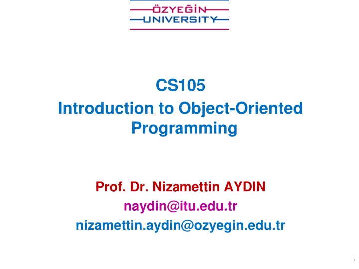
CS105 Introduction to Object-Oriented Programming Prof. Dr. Nizamettin AYDIN naydin@itu.edu.tr nizamettin.aydin@ozyegin.edu.tr 1
Outline UML (Unified Modeling Language) Goals of UML Characteristics of UML Conceptual Modelling Uses for UML UML Class Diagram Purpose of Class Diagrams Benefits of Class Diagrams Vital components of a Class Diagram Relationships between classes Class Diagram Examples 3
UML (Unified Modeling Language) a standardized general-purpose, graphical modeling language in the field of Software Engineering. used to specify, visualize, construct, and document the artifacts (major elements) of the software system. helps in designing and characterizing, especially those software systems that incorporate the concept of Object orientation. describes the working of both the software and hardware systems. 4
Goals of UML Since it is a general-purpose modeling language, it can be utilized by all the modelers. UML came into existence after the introduction of object-oriented concepts to systemize and consolidate the object-oriented development, due to the absence of standard methods at that time. The UML diagrams are made for business users, developers, ordinary people, or anyone who is looking forward to understand the system, such that the system can be software or non-software. UML is a simple modeling approach that is used to model all the practical systems. 5
Characteristics of UML The UML has the following features: It is a generalized modeling language. It is distinct from other programming languages like C++, Python, etc. It is interrelated to object-oriented analysis and design. It is used to visualize the workflow of the system. It is a pictorial language, used to generate powerful modeling artifacts. 6
Conceptual Modeling A conceptual model is composed of several interrelated concepts makes it easy to understand the objects and how they interact with each other. This is the first step before drawing UML diagrams. Following are some object-oriented concepts that are needed to begin with UML: 7
Conceptual Modeling Following are some object-oriented concepts that are needed to begin with UML: Object: An object is a real world entity. There are many objects present within a single system. It is a fundamental building block of UML. Class: a software blueprint for objects, which means that it defines the variables and methods common to all the objects of a particular type. Abstraction: the process of portraying the essential characteristics of an object to the users while hiding the irrelevant information. Basically, it is used to envision the functioning of an object. Inheritance: the process of deriving a new class from the existing ones. Polymorphism: a mechanism of representing objects having multiple forms used for different purposes. Encapsulation: binds the data and the object together as a single unit, enabling tight coupling between them. 8
Uses for UML As a sketch: to communicate aspects of system forward design: doing UML before coding backward design: doing UML after coding as documentation often done on whiteboard or paper used to get rough selective ideas As a blueprint: a complete design to be implemented sometimes done with CASE (Computer-Aided Software Engineering) tools As a programming language: with the right tools, code can be auto-generated and executed from UML only good if this is faster than coding in a "real" language 10
UML Class Diagram What is a UML class diagram? a picture of the classes in an OO system, their fields and methods, and connections between the classes that interact or inherit from each other. shows the attributes, classes, functions, and relationships to give an overview of the software system. constitutes class names, attributes, and functions in a separate compartment that helps in software development. What are some things that are not represented in a UML class diagram? details of how the classes interact with each other algorithmic details; how a particular behavior is implemented 11
Purpose of Class Diagrams to build a static view of an application. It is the only diagram that is widely used for construction, and it can be mapped with object-oriented languages. It is one of the most popular UML diagrams. Following are the purpose of class diagrams given below: It analyses and designs a static view of an application. It describes the major responsibilities of a system. It is a base for component and deployment diagrams. It incorporates forward and reverse engineering. 12
Benefits of Class Diagrams It can represent the object model for complex systems. It reduces the maintenance time by providing an overview of how an application is structured before coding. It provides a general schematic of an application for better understanding. It represents a detailed chart by highlighting the desired code, which is to be programmed. It is helpful for the stakeholders and the developers. 13
Vital components of a Class Diagram The class diagram is made up of three sections: Upper Section: encompasses the name of the class. A class is a representation of similar objects that shares the same relationships, attributes, operations, and semantics. rules that should be taken into account while representing a class: Capitalize the initial letter of the class name. Place the class name in the center of the upper section. A class name must be written in bold format. The name of the abstract class should be written in italics format. 14
Vital components of a Class Diagram The class diagram is made up of three sections: Middle Section: constitutes the attributes, which describe the quality of the class. visibility name : type [count] = default_value The attributes have the following characteristics: The attributes are written along with its visibility factors, which are public (+), private (-), protected (#), and package/default (~), derived (/). derived attribute: not stored, but can be computed from other attribute values The accessibility of an attribute class is illustrated by the visibility factors. A meaningful name should be assigned to the attribute, which will explain its usage inside the class. underline static attributes attribute example: - balance : double = 0.00 15
Vital components of a Class Diagram The class diagram is made up of three sections: Lower Section: The lower section contain methods or operations. visibility name (parameters) : return_type underline static methods method example: + distance(p1: Point, p2: Point): double The methods are represented in the form of a list, where each method is written in a single line. omit return_type on constructors and when return type is void It demonstrates how a class interacts with data. 16
Comments represented as a folded note, attached to the appropriate class/method/etc by a dashed line 17
Perspectives of Class Diagram The choice of perspective depends on how far along you are in the development process. A diagram can be interpreted from various perspectives: Conceptual: represents the concepts in the domain Specification: focus is on the interfaces of Abstract Data Type (ADTs) in the software Implementation: describes how classes will implement their interfaces the class name is the only mandatory information 18
Relationships between classes A class may be involved in one or more relationships with other classes. A relationship can be one of the following types: 19
Relationships between classes Generalization (Inheritance): a relationship between a parent class (superclass) and a child class (subclass). Represents an "is-a" relationship. An abstract class name is shown in italics. inheritance between classes The child class is inherited from the parent class. SubClass1 and SubClass2 are specializations of SuperClass inheritance example with two styles. they are semantically equivalent. 20
Relationships between Classes Association: describes a static or physical connection between two or more objects. depicts how many objects are there in the relationship. a usage relationship aggregation Composition dependency For example, a department is associated with the college. 21
Relationships between Classes Association: Simple association A structural link between two peer classes. There is an association between Class1 and Class2 The figure below shows an example of simple association. There is an association that connects the <<control>> class Class1 and <<boundary>> class Class2. The relationship is displayed as a solid line connecting the two classes. 22
Relationships between Classes Association: Multiplicity (Cardinality) expressed in terms of: one to one one to many many to many Associational (usage) relationships 1. multiplicity (how many are used) * 0, 1, or more 1 1 exactly 2..4 between 2 and 4, inclusive 3..* 3 or more 2. name (what relationship the objects have) 3. navigability (direction) 23
Multiplicity of associations one-to-one each student must carry exactly one ID card one-to-many one rectangle list can contain many rectangles 24
Relationships between Classes Association: Aggregation A special type of association. It represents an is part of" relationship. Class2 is part of Class1. Many instances (denoted by the *) of Class2 can be associated with Class1. Objects of Class1 and Class2 have separate lifetimes. The figure below shows an example of aggregation. The relationship is displayed as a solid line with a unfilled diamond at the association end, which is connected to the class that represents the aggregate. The company encompasses a number of employees, and even if one employee resigns, the company still exists. 25
Relationships between Classes Association: Composition A stronger version of aggregation, where parts are destroyed when the whole is destroyed Objects of Class2 live and die with Class1 Class2 cannot stand by itself. It represents an "is entirely made of" relationship. The figure below shows an example of composition. The relationship is displayed as a solid line with a filled diamond at the association end, which is connected to the class that represents the whole or composite. A contact book consists of multiple contacts, and if you delete the contact book, all the contacts will be lost. 26
Relationships between Classes Association: Dependency A special type of association that forms a weaker relationship. symbolized by a dotted line A semantic relationship between two or more classes, where a change in one class cause changes in another class, but not the other way around The figure below shows an example of dependency. The relationship is displayed as a dashed line with an open arrow. The Person class might have a hasRead method with a Book parameter that returns true if the person has read the book (perhaps by checking some database). 27
Abstract Classes In the abstract class, no objects can be a direct entity of the abstract class. can neither be declared nor be instantiated. It is used to find the functionalities across the classes. written in italics. It is best to use the abstract class with multiple objects. Assume that we have an abstract class named displacement with a method declared inside it, and that method will be called as a drive (). This abstract class method can be implemented by any object, for example, car, bike, scooter, cycle, etc. 28
How to draw a Class Diagram? The class diagram is used most widely to construct software applications. It not only represents a static view of the system but also all the major aspects of an application. A collection of class diagrams as a whole represents a system. Key points to keep in mind while drawing a class diagram: Give a meaningful name to the class diagram. Objects and their relationships should be acknowledged in advance. Attributes and methods of each class must be known. A minimum number of desired properties should be specified more number of the unwanted property will lead to a complex diagram. Notes can be used as and when required by the developer to describe the aspects of a diagram. The diagrams should be redrawn and reworked as many times to make it correct before producing its final version. 29
Class Diagram Example: Rental System Multiplicity Customer 1 Simple Aggregation Class Rental Invoice Abstract Class 1..* Rental Item 1 0..1 Composition Simple Association Generalization Checkout Screen DVD Movie VHS Movie Video Game 31
Class Diagram Example: Student Record StudentBody StudentBody Student Student 1 100 - - firstName : String firstName : String - - lastName : String lastName : String - - homeAddress : Address homeAddress : Address - - schoolAddress : Address schoolAddress : Address + main (args : String[]) + main (args : String[]) + toString() : String + toString() : String Address Address - - streetAddress : String streetAddress : String - - city : String city : String - - state : String state : String - - zipCode : long zipCode : long + toString() : String + toString() : String 32
Class Diagram Example: GUI A class diagram may also have notes attached to classes or relationships. 34
Tools for creating UML diagrams ClickUp https://clickup.com/ Violet http://horstmann.com/violet/ Rational Rose https://www.ibm.com/support/pages/ibm-rational-rose-enterprise-7004-ifix001 Visual Paradigm UML Suite http://www.visual-paradigm.com/ SmartDraw https://www.smartdraw.com/ EdrawMax https://www.edrawsoft.com/ Lucidchartx https://www.lucidchart.com/ there are many others, but most are commercial 36


