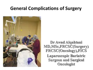
INTRA-OPERATIVE NEUROPHYSIOLOGICAL MONITORING
Intra-operative neurophysiological monitoring provides real-time feedback to the surgical team, aiding in preventing neural pathway injuries. Explore the history of EEG and ECOG techniques. Learn about methods such as SSEP, Spinal MEP, and more for monitoring neurological function during surgery.

Download Presentation

Please find below an Image/Link to download the presentation.
The content on the website is provided AS IS for your information and personal use only. It may not be sold, licensed, or shared on other websites without obtaining consent from the author.If you encounter any issues during the download, it is possible that the publisher has removed the file from their server.
You are allowed to download the files provided on this website for personal or commercial use, subject to the condition that they are used lawfully. All files are the property of their respective owners.
The content on the website is provided AS IS for your information and personal use only. It may not be sold, licensed, or shared on other websites without obtaining consent from the author.
E N D
Presentation Transcript
INTRA-OPERATIVE NEUROPHYSIOLOGICAL MONITORING
Intra-op Neurophysiological Monitoring Real time feed-back information to the surgical team about the functional status of neural pathways under surgical manipulation preventive or corrective actions to avoid irreversible injuries. Team of Neurosurgeon, Neurophysiologist and neuroanesthesiologist is ideal. Ideal Technique High Sensitivity High Specificity Low invasiveness Ease of use
HISTORY-Spinal 1983: National Orthopaedic Hospital group(UK) SSEP Late 1980s: motor tract monitoring-- Merton and Merton 1973 Wake up test: Vauzelle and Stagna 1972- Tetsuya Tamaki group from Japan -- utilize SCEP 1970- aggressive spinal technology Nash from USA-- SSEP
History EEG and ECOG Han Berger in 1928-29 was the first to report EEG tracings from human brains. The first use of intraoperative EEG was by Foerster and Alternberger in 1935. In the late 1930s through the 1950s, Herbert Jasper and Wilder Penfield further developed this technique, using ECoG for localization and surgical treatment of epilepsy. They also performed careful mapping of cortical function by direct electrical stimulation.
Methods SSEP: somatosensory evoked potential after stimulation of a peripheral nerve Spinal MEP: spinal cord evoked potential after stimulation of the motor cortex Muscle MEP (brain): muscle evoked potential after stimulation of the motor cortex Muscle MEP (spinal cord): muscle evoked potential after stimulation of the spinal cord EMG : Muscle evoked potential after stimulation of peripheral nerves ECOG : is the practice of using electrodes placed directly on the exposed surface of the brain to record electrical activity from the cerebral cortex Scalp EEG : Surface recording of cortical activity of brain
Somato-sensory Evoked Potential Monitors Dorsal column integrity Most commonly used technique in spine surgery Stimulation sites UL Median/Ulnar nerves LL -- Posterior tibial nerve Excitatory controlled repetitive action potentials propagating from peripheral nerves to dorsal roots, posterior column and finally to contralateral sensory cortex Stimulation waveforms 250 us square wave pulse trains at 4.7 Hz and 20-40 mA stimulation amplitudes Recording scalp electrodes follow 10-20 system (Standardized by American Electroencephalographic society)
The international 10-20 system seen from the left (A) and above the head (B). A, ear lobe; C, central; F, frontal; Fp, frontal polar; P, parietal; Pg, nasopharyngeal; O, occipital. C, Location and nomenclature of the intermediate 10% electrodes, as standardized by the American Electroencephalographic Society.
SSEP Contd.. Neural stimulation of the lower extremities also checks integrity of spinocerebellar tracts, which involve the dorsal nucleus of Clarke s column between T1 and L2. Comparison is made with the post-induction baseline measurements. >= 50% decrease in amplitude and associated 10% increase in latency significant Non-surgical variables Depth of anesthesia, Temp., and MAP Signals Subcortical : Lower amplitude and reduced signal to noise ratio but more resistant to depth of anesthesia Cortical : Larger amplitude and higher signal to noise ratio (Tend to be more reliable electrically) but more sensitive to depth of anesthesia Disadvantage Motor deficits can not be predicted.
Motor Evoked Potential (MEP) Transcranial electrical/ magnetic stimulation of the cerebral motor cortex causes muscle activation. Role in Intramedullary tumors and procedures with a risk for vascular compromise of anterior spinal artery. Scalp electrodes are placed according to 10-20 system. D-waves (Direct) Single pulse stimulation and corticospinal tract readings I- Waves (Indirect)- Resultant waves from ascending vertically oriented excitatory chains of neurons terminating on cortical motor neurons Abolished by anesthetic agents. Recording of D-waves by Epidural electrodes placed cranially and caudally to op site.
MEP Contd.. Reduction of >= 50% in D-wave amplitude have been shown to correlate with new post-operative deficits. CMAPs Multipulse stimulation techniques short pulse trains are used Recordings of CMAP done at thenar muscles/ tibialis anterior CMAPs Monitors Both Cortico-spinal tracts and distal muscle functional units including NM junction Myogenic MEPs are interpreted as all or none phenomenon
ElectroMyoGraphy SSEP cannot evaluate individual nerve roots Operative Monitoring Nerve irritation Nerve identification (stimulation) Pedicle screw testing Reflex testing (Motor evoked potentials) www.springerimages.com
Electromyography (EMG) Types Continuous/ Triggered Sensitive to surgical manipulation of peripheral nerves spinal surgeries with risk of radicular injury (TCS/Ped. Screw fixation) Continuous EMG Paired stainless steel needle electrodes insulated to within 5 mm of the tip and transdermally inserted into the target muscle Electrode impedence below 5 k and interelectrode impedence below 1 k acceptable Morphology of EMG Spikes : individual discharges Bursts : Brief bundles of discharges Train activity: Persistently regular repeated discharge patterns Neurotonic discharges : Persistent prolonged bursting Sustained activity (> 2 sec) -- significant
Triggered/Evoked EMG Obtained from suspicious tissues scar, tumor, filum Reflects functional integrity between interrogated tissue and muscle units being recorded. Stimulation Bipolar probe delivers monophasic square wave pulses of 3 Hz, duration 100 microsec and a constant current source less than 10 mA Continuous EMG has high sensitivity but low specificity in predicting post-operative neurological deficits.
Which Nerves? Cervical Thoracic Lumbosacral Sacral C2, C3, C4 C5, C6 C6, C7 C8, T1 Trapezius, Sternocleidomastoid Spinal portion of the spinal accessory n. Biceps, Deltoid Flexor Carpi Radialis Abductor Pollicis Brevis, Abductor Digiti Minimi T5, T6 T7, T8 T9, T10, T11 T12 Upper Rectus Abdominis Middle Rectus Abdominis Lower Rectus Abdominis Inferior Rectus Abdominis L2, L3, L4 L4, L5, S1 L5, S1 Vastus Medialis Tibialis Anterior Peroneus longus S1, S2 S2, S3, S4 Gastrocnemius External anal sphincter
Comparison MODALITIES SSEPs MEPs/CMAPs EMG Free-running: none Triggered: bipolar stimulation of a specific structure Peripheral sensory nerves Transcranial scalp electrodes Stimulation Cortical and cervicomedullary junction Extremity muscles (e.g., thenar muscles, tibialis anterior) Recording Myotome specific 50% reduction in amplitude 10% increase in latency Disappearance of signal (all-or-none phenomenon) Sustained activity (>2 sec) Alert threshold
MODALITIES SSEPs MEPs/CMAPs EMG Specific and sensitive to sensory deficits Continuous monitoring, no interruption in surgical manoeuvres Specific and sensitive to motor deficits Large signal amplitude, instantaneous feedback Allows surgical correlation with specific nerve roots Continuous monitoring Instantaneous feedback Advantages False-negative results for motor deficits Low signal amplitude, multitrace averaging required, delayed response (seconds to minutes) Total intravenous anaesthesia Intermittent monitoring, interruption in surgery required No neuromuscular blockade Monitors only nerve roots Disadvantages
References SSEP & EMG Reciprocal sensitivity and specificity of SSEPs and EMG in thoraco-lumbar spine surgeries SSEP Sensitivity 28.6% and Specificity 94.7 % EMG Sensitivity 100 % and Specificity 23.7 % ** Gunnarsson T et al: Real-time continuous intraoperative electromyographic and somatosensory evoked potential recordings in spinal surgery: Correlation of clinical and electrophysiologic findings in a prospective, consecutive series of 213 cases. Spine 2004; 29:677-684.
SSEP in Endoscopic endonasal approach The incidence of changes in SSEP during the procedure was 20 of 976 (2%). The incidence of new postoperative neurological deficits was 5 of 976 (0.5%). The positive and negative predictive values of SSEPs during EEA to predict neurovascular deficits were 80.00% and 99.79%, respectively. Neurosurgery. 2011 Sep;69(1 Suppl Operative):ons64-76; discussion ons76. Somatosensory evoked potential monitoring during endoscopic endonasal approach to skull base surgery: analysis of observed changes. Thirumala PD Department of Neurological Surgery, University of Pittsburgh, Pittsburgh, Pennsylvania
Cost Factor analysis Assuming an average of 4 hours of monitoring time per surgical case, the savings realized in this group of patients was estimated to be $1,024,754.This study demonstrates that decompression and reconstruction for symptomatic cervical spine disease without IOM may reduce the cost of treatment without adversely impacting patient safety. J Neurosurg Spine. 2011 Nov 11. [Epub ahead of print] Cervical decompression and reconstruction without intraoperative neurophysiological monitoring. Traynelis VC, Department of Neurosurgery, Rush University Medical Center, Chicago, Illinois
Role of EMG in minimally invasive Sx In minimally invasive approaches to the spine, the use of EMG IOM might provide additional safety, such as percutaneous pedicle screw placement, where visualization is limited compared with conventional open procedures. In addition to knowledge of the anatomy and image guidance, directional EMG IOM is crucial for safe passage through the psoas muscle during the minimally invasive lateral retroperitoneal approach. Spine (Phila Pa 1976). 2010 Dec 15;35(26 Suppl):S368-74. Electromyographic monitoring and its anatomical implications in minimally invasive spine surgery. Uribe JS Department of Neurosurgery and Brain Repair, University of South Florida, Tampa, FL, USA
MEP in glioma and pediatric population Intraoperative monitoring of motor evoked potentials in very young children < 3yrs J Neurosurg Paediatric. 2011 Apr;7(4):331-7. Fulkerson DH Neuro-Spine Program, Division of Paediatric Neurosurgery, Texas Children's Hospital, Department of Neurosurgery, Baylor College of Medicine, Houston, Texas 77030, USA. Predictive value and safety of intraoperative neurophysiological monitoring using motor evoked potentials in glioma surgery. Neurosurgery.2011 Nov 3. [Epub ahead of print] Krieg SM Department of Neurosurgery, Technische Universit t M nchen, Munich, GermanySandro
MEP + SSEP Preventing position-related brachial plexus injury with intraoperative somatosensory evoked potentials and transcranial electrical motor evoked potentials during anterior cervical spine surgery. Am J Electroneurodiagnostic Technol. 2011 Sep;51(3):198-205. Jahangiri FR Impulse Monitoring, Inc., Columbia, Maryland, USA.
MEP in aneurysm Sx The use of motor evoked potential monitoring during cerebral aneurysm surgery to predict pure motor deficits due to subcortical ischemia. Clin Neurophysiol. 2011 Apr;122(4):648-5 Guo L Neurophysiological Monitoring Service, University of California, San Francisco, Box 0220, 533 Parnassus Avenue, U-491, San Francisco, CA The value of intraoperative neurophysiological monitoring in tethered cord surgery. Childs Nerv Syst.2011 Sep;27(9):1445-52. Epub 2011 May 3. Hoving Department of Neurosurgery, University Medical Centre Groningen, The Netherlands.
External Anal/Urethral sphincter EMG Monitoring Lumbosacral surgery for tumor resection/ detethering S2-S4 nerve roots monitored Insertion of urethral ring electrode facilitated by 2- way foley s with electrode applied 1-2 cm proximal to the inflated balloon Insertion of anal sphincter electrode is performed similar to rectal temperature probes.
FACTORS AFFECTING EPS RECORDING UNDER ANESTHESIA HYPOTHERMIA HYPOXIA HYPOTENSION/ISCHEMIA ANESTHETIC AGENTS SURGICAL FACTORS: INJURY-COMPRESSION- RETRACTION
ANESTHETIC EFFECTS ON EPS LATENCY DELAY AMPLITUDE REDUCTION (EXCEPT ETOMIDATE AND KETAMINE) VARIABLE AMONG AGENTS WORSE IN INHALATIONAL AGENTS AND DOSE DEPENDANT ADDITIVE EFFECTS OF AGENTS VEP>SSEP>BAER
Compound Nerve Action Potential (CNAP) Combined activity of all the axons taken together Each individual axon shows all/none phenomenon but CNAP varies continuously to a maximum amplitude Amplitude Numbers of axons that fire together CNAP is a reflection of general histology of a particular nerve In an effort to record the difference in potential that is the CNAP, we must provide contact with the nerve at the active length of the nerve, as well as contact with the nerve at a point that does not contain active axons.
CNAP Contd.. The distance between the stimulating and recording electrodes also has limitations. Stimulus artefact is a common problem encountered in operative recordings. When the distance between the stimulating and recording electrodes is less than approximately 2 cm, the amount of stimulus artifact becomes so great that it can obscure a small CNAP. Particularly important in children. Another source of excessive stimulus artifact is the wires connected to the electrodes. When both the stimulating and recording wires exit the surgical field together and in close proximity, artifact is induced in the recording wires from the stimulating wires
Cont When relatively long-duration stimulus pulses are used, on the order of 0.2 msec, stimulus artefact is considerable. Reducing stimulus duration to a value between 0.02 and 0.05 msec provides considerably less stimulus artefact. Very proximal avulsive nerve injuries are monitored better by SSEP/MEP.
Methods for Cranial Nerve Monitoring II Optic III Oculomotor IV Trochlear V Trigeminal VI Abducens VII Facial VIII Auditory IX Glossopharyngeal X Vagus XI Spinal Accessory XII Hypoglossal motor: inferior rectus m motor: superior oblique m motor: masseter and/or temporalis m motor: lateral rectus m motor: orbicularis oculi and/or orbicularis oris m sensory: ABR motor: posterior soft palate (stylopharyngeus m) motor: vocal folds, cricothyroid m motor: sternocleidomastoid m and/or trapezius m motor: tongue, genioglossus m sensory: VEP
Introduction - VEP The VEP tests the function of the visual pathway from the retina to the occipital cortex. It assesses the integrity of the visual pathways from the optic nerve, optic chiasm, and optic radiations to the occipital cortex. Visual Cortex (occipital lobe) The generator site is believed to be the peristriate and striate occipital cortex
Cont.. The VEP is very useful in detecting an anterior visual conduction disturbance. However, it is not specific with regard to etiology. For example a tumor compressing the optic nerve, an ischemic disturbance, or a demyelinating disease may cause delay in the P100. Apply three scalp electrodes at; Oz : 2cms above the inion. Cz : at vertex Fz : on frontal bone.
Waveforms (The NPN complex) The initial negative peak (N1 or N75) A large positive peak (P1 or P100) Negative peak (N2 or N145)
Maximum Value for P100 P100 is 110 milliseconds (ms) in patients younger than 60 years (it rises to 120 ms thereafter in females and 125 ms in males. ) Interocular P100 latency difference is upto 5 6 msec. > 10ms is gross abnormality. Negative components of NPN complex may be absent even in normal subject. The only persistent wave is P100.
Limitation Cannot predict visual field defects
What is an ABR? The Auditory Brainstem Response is the representation of electrical activity generated by the eighth cranial nerve and brainstem in response to auditory stimulation
How is an ABR recorded? Electrodes are placed on the scalp and coupled via leads to an amplifier and signal averager. EEG activity from the scalp is recorded while the ear(s) are stimulated via earphones with brief clicks or tones. A series of waveforms unique to the auditory neural structures is viewed after time-locking the EEG recording to each auditory stimulus and averaging several thousand recordings.
Interpretation Positive deflections are termed waves I-VII. Waves I, III, and V are the waves most consistently seen in healthy subjects (obligate waves). Wave V is the most reliably seen wave, particularly in patients with hearing impairment or undergoing surgery. A shift in latency of 1 millisecond or a drop in amplitude of 50% could be significant and should be reported to the surgeon.
Clinical uses Cerebellopontine angle surgery: This includes surgery for acoustic neuroma or meningioma, or for microvascular decompression for tic douloureux or hemifacial spasm. Important parameters to monitor include peak amplitude of waves III and V, latency of wave V, latency of waves I-V, and latency of waves I-III. If changes occur, they may be due to improper retraction on the cerebellum and brain stem; these may be reversible with a change of position of the retractors by the surgeon.
Intra-operative EEG - Technique Intraoperative scalp EEG recordings can be performed using standard electrodes and paper or digital EEG machines. Because of the difficulty of re-applying electrodes in the operating room, a secure scalp-electrode interface must be assured, usually by using collodion with a cup electrode. In certain circumstances, an electrode cap or needle electrodes may be useful. Standard 10-20 electrode placement is used typically, and signals are recorded in 8- 32 channels of bipolar, with or without referential, derivations. Because of the need to monitor beta activity, high-frequency filters less than 35 Hz should not be used
Interpretation The most important requirement for intraoperative EEG recording is knowledge of expected changes with deepening levels of anaesthesia. Premedication with barbiturates or benzodiazepines causes increased beta activity and then successively increased slowing. With induction, frontal intermittent delta activity (FIRDA) often is observed, or perhaps transient (< 1 min) burst suppression if induction is rapid. Then diffuse faster activity is seen, typically slowing from beta to alpha frequencies, superimposed on variable theta and delta, depending on depth of anaesthesia. Still deeper stages sometimes can produce burst suppression.
Intra-operative changes The most important lateralized or localized changes include loss of fast activity along with increase in slow activity. These lateralized or localized changes generally reflect focal decrease in cerebral blood flow resulting from either acute change in vessel calibre or hypotension in the setting of a fixed stenosis.
Uses The most common use of scalp EEG for intraoperative monitoring is during carotid endarterectomy. EEG changes are reliable guides to acute changes in cerebral blood flow that occur, for example, during carotid cross-clamping. These usually are seen within 30 seconds and indicate a need for shunting. Embolization during or after the procedure also can manifest as lateralized or localized EEG changes. Other uses of scalp EEG include during aneurysm repair when carotid clamping is required and during hypothermic circulatory arrest for cardiac surgery.
Electrocorticography -- Technique Intraoperative ECoG can be recorded by using saline- soaked cotton or carbon ball electrodes attached by flexible wires to a frame fixed to the skull, or by using stainless steel or platinum disc electrodes embedded in silastic, similar to those used routinely for long-term extra operative recording. The signal is recorded with a standard paper or digital EEG machine and displayed in bipolar and/or referential derivations. Optimal sensitivity settings usually range between 20 and 70 V/mm, with a high-frequency filter of 70 Hz
Use of ECoG for identification of functional brain areas ECoG stimulations: determine critical location by disrupting the function. ECoG recordings: mapping endogenous cortical function, reflecting normal cortical function.
Interpretation Epileptiform spikes are significantly sharper at the cortical surface than at the scalp and often have durations of only 10-20 milliseconds. Cortical regions producing frequent spikes, occurring periodically to continuously, almost certainly need to be resected for optimal seizure outcome. As noted later, deep anaesthesia with most agents suppresses spikes, while methohexital boluses of up to 1 mg/kg can at times be activating. In awake patients, encouragement to relax and become drowsy can be a more physiologic activation method.
Clinical uses To ameliorate seizures. In lesional cases, seizure outcome is most dependent on complete lesion resection, but removing surrounding areas that show very frequent spiking probably can improve outcome further and also may help if the lesion cannot be removed completely. In the special case of cortical dysplastic lesions, ictal or near-ictal ECoG patterns are common, and may guide resection when the margins are not clear on direct inspection or on neuroimaging.
Uses Cont Nonlesional cases usually rely on extraoperative recording of seizure onsets using indwelling depth or subdural electrodes, but margins sometimes can be refined using intraoperative ECoG In the case of mesial temporal lobe epilepsy, ECoG recorded from the lateral temporal cortex is of questionable utility, but recording from the parahippocampal region can assist in determining the posterior resection margin.
Cortical Electrical Stimulation Technique "Mapping" of functional cortex by electrical stimulation still is considered the criterion standard of determining areas whose resection risks causing neurologic deficits. Usually bipolar stimulation is performed with either the same silastic embedded disc electrodes used for recording, or a movable, hand-held bipolar stimulator including 2 closely spaced spherical electrodes. The stimulus is an alternating square-wave pulse of 0.3- 2 milliseconds duration at 50-75 Hz, with currents between 0.5-15 milliampere applied for 4-8 seconds.
Technique Cont In the lightly anesthetized patient, motor cortex can be localized, but the patient must be awake for testing sensation, language, and at times memory formation. Motor-inhibitory areas also can be localized by using continuous motor tasks. Language tasks can include spontaneous speech, recitation, reading, and naming.


 and")

")


")