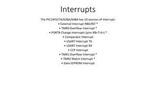
Interrupts in MSP430 Microcontroller
This content delves into the basics of interrupts in the MSP430 microcontroller. It covers how interrupts work, the need for interrupts, handling interrupts efficiently, and the processor's perspective on managing interrupts. The material explores the significance of interrupts in enabling the CPU to handle external events, go into low-power modes, and execute other tasks while waiting for specific events. It also discusses the requirements for implementing interrupts and outlines the process of interrupt handling in the MSP430 platform.

Download Presentation

Please find below an Image/Link to download the presentation.
The content on the website is provided AS IS for your information and personal use only. It may not be sold, licensed, or shared on other websites without obtaining consent from the author.If you encounter any issues during the download, it is possible that the publisher has removed the file from their server.
You are allowed to download the files provided on this website for personal or commercial use, subject to the condition that they are used lawfully. All files are the property of their respective owners.
The content on the website is provided AS IS for your information and personal use only. It may not be sold, licensed, or shared on other websites without obtaining consent from the author.
E N D
Presentation Transcript
CS4101 Interrupts Prof. Chung-Ta King Department of Computer Science National Tsing Hua University, Taiwan Materials from MSP430 Microcontroller Basics, John H. Davies, Newnes, 2008 National Tsing Hua University
From Clock to Timer to CPU 1 National Tsing Hua University
How Does CPU Know Timer Is Up? #define LED1 BIT0 void main(void) { WDTCTL = WDTPW|WDTHOLD; // Stop watchdog timer P1OUT = ~LED1; P1DIR = LED1; TA0CCR0 = 49999; TA0CTL = MC_1|ID_3|TASSEL_2|TACLR; //Setup Timer_A for (;;) { // Loop forever while(TA0CTL_bit.TAIFG == 0) { } // Wait overflow TA0CTL_bit.TAIFG = 0; // Clear overflow flag P1OUT = LED1; // Toggle LEDs } } Polling 2 National Tsing Hua University
Problem with Polling CPU is in the loop forever Question: How can it do other useful things, e.g. handling external events? or go into low-power modes? Solution: Let CPU be notified when the timer is up! Before that, CPU can do other useful things or go to sleep The notification forces CPU to start handling the event of timer up The notification is an interrupt! 3 National Tsing Hua University
Interrupts Requirements: Must let the processor know when the event occurs Must let the processor know where to jump to execute the handling code Must not allow your program know!! you program must execute as if nothing happens must store and restore your program state 4 National Tsing Hua University
Outline Introduction to interrupt Interrupts of MSP430 Handling interrupts of Timer0_A in MSP430 Handling interrupts of port P1 in MSP430 5 National Tsing Hua University
Interrupt: Processors Perspective How does the processor know when there is an interrupt? Usually when it receives a signal from one of the IRQ (interrupt request) pins 6 National Tsing Hua University
Interrupt: Processors Perspective What does the processor do in handling an interrupt? When receiving an interrupt signal, the processor stops at the next instruction and saves the address of the next instruction on the stack and jumps to a specific interrupt service routine (ISR) ISR is basically a subroutine to perform operations to handle the interrupt with a RETURN at the end How to be transparent to the running prog.? The processor has to save the state of the program onto the stack and restoring them at the end of ISR 7 National Tsing Hua University
Interrupt Service Routine The following shows an example of an ISR Task Code ... MOVE R1, R7 MUL R1, 5 ADD R1, R2 DIV R1, 2 JCOND ZERO, END SUBTRACT R1, R3 ... ... END: MOVE R7, R1 ... ISR PUSH R1 PUSH R2 ... ;ISR code comes here ... POP R2 POP R1 RETURN ... 8 National Tsing Hua University
Disabling Interrupts Programs may disable interrupts In most cases the program can select which interrupts to disable during critical operations and which to keep enabled by writing corresponding values into a special register Nonmaskable interrupts cannot be disabled and are used to indicate critical events, e.g. power failures Certain processors assign priorities to interrupts, allowing programs to specify a threshold priority so that only interrupts having higher priorities than the threshold are enabled 9 National Tsing Hua University
Where to Put ISR Code? Challenges: Locations of ISRs should be fixed so that the processor can easily find them But, different ISRs may have different lengths hard to track their starting addresses Worse yet, application programs may supply their own ISRs; thus ISR codes may change dynamically Possible solutions: ISR is at a fixed location, e.g., in 8051, the first interrupt pin always causes 8051 to jump to 0x0003 A table in memory contains addresses of ISR the table is called interrupt vector table 10 National Tsing Hua University
How to Know Who Interrupts? Simple answer: according to interrupt signal One interrupt signal corresponds to one ISR Difficult problem: same interrupt signal shared by several devices/events Option 1: inside the corresponding ISR, poll and check these devices/events in turn devices are passive Option 2: devices/events provide the address of ISRs devices are proactive vectored interrupt 11 National Tsing Hua University
Some Common Questions Can a processor be interrupted in the middle of an instruction? Usually not Exceptions: critical hardware failure, long-running instructions (e.g. moving data in memory) If two interrupts occur at the same time, which ISR does the process do first? Prioritize the interrupt signals Can an interrupt signal interrupt another ISR? Interrupt nesting is usually allowed according to priority Some processor may require re-enabling by your ISR 12 National Tsing Hua University
Some Common Questions What happens when an interrupt is signaled while the interrupt is disabled? Processors usually remember the interrupt signals and jump to the ISR when the interrupt is enabled What happens when we forget to re-enable disabled interrupts? What happens if we disable a disabled interrupt? Are interrupts enabled or disabled when the processor first starts up? 13 National Tsing Hua University
Interrupt Latency Interrupt latency is the amount of time taken to respond to an interrupt. It depends on: 1. Longest period during which the interrupt is disabled 2. Time to execute ISRs of higher priority interrupts 3. Time for processor to stop current execution, do the necessary bookkeeping and start executing the ISR 4. Time taken for the ISR to save context and start executing instructions that count as a response Make ISRs short Factors 4 and 2 are controlled by writing efficient code that are not too long Factor 3 depends on HW, not under software control 14 National Tsing Hua University
Outline Introduction to interrupt Interrupts of MSP430 Handling interrupts of Timer0_A in MSP430 Handling interrupts of port P1 in MSP430 15 National Tsing Hua University
Three Types of Interrupts in MSP430 System reset: Power-up, external reset, Watchdog Timer, flash key violation, PC out-of-range, etc. Always take (Non)-maskable interrupt (NMI): RST/NMI pin, oscillator fault, flash access violation Cannot be masked; but still need bits to be set in special peripheral registers Maskable interrupt Enable the interrupt Prepare the interrupt service routine (ISR) and link it to the interrupt 16 National Tsing Hua University
Enabling an Interrupt On MSP430, an interrupt will be detected and serviced if The global interrupt-enable (GIE) bit in Status Register (SR) in CPU is set A peripheral device enables interrupt For Timer0_A: TAIE bit in TA0CTL register, CCIE bit in TA0CCTLx register The peripheral signals an interrupt For Timer0_A: TAIFG, CCIFG 17 National Tsing Hua University
Ex: Timer0_A Interrupt Enabling TA0CTL TA0CCTL 18 National Tsing Hua University
When an Interrupt Is Requested Any currently executing instruction is completed. MCLK is started if the CPU was off. The PC, which points to the next instruction, is pushed onto the stack. The SR is pushed onto the stack. The interrupt with the highest priority is selected. The interrupt request flag is cleared automatically for interrupts that have a single source. The SR is cleared, and other maskable interrupts are disabled. The starting address of ISR is loaded into the PC and the CPU starts to execute the ISR at that address. These operations take about 6 cycles 19 National Tsing Hua University
After an Interrupt Is Serviced An interrupt service routine must always finish with the return from interrupt instruction reti: The SR pops from the stack. All previous settings of GIE and the mode control bits are now in effect. enable other maskable interrupts and restores the previous low-power mode if there was one. The PC pops from the stack and execution resumes at the point where it was interrupted. Alternatively, the CPU stops and the device reverts to its low-power mode before the interrupt. The original program runs as if there were no interrupt. 20 National Tsing Hua University
Where to Find ISRs? MSP430 uses vectored interrupts Each ISR has its own vector (starting address), which is stored at a predefined address in a vector table at the end of the program memory (addresses 0xFFE0 ~ 0xFFFF). The vector table is at a fixed location, but the ISRs themselves can be located anywhere in memory. 21 National Tsing Hua University
System Interrupt Word Address Interrupt Source Interrupt Flag Priority Power-up/external reset/Watchdog Timer+/flash key viol./PC out-of-range NMI/Oscillator Fault/ Flash access viol. Timer1_A3 Timer1_A3 Comparator_A+ Watchdog Timer+ Timer0_A3 PORIFG RSTIFG WDTIFG KEYV NMIIFG/OFIFG/ ACCVIFG TA1CCR0 CCFIG TA1CCR1/2 CCFIG, TAIFG CAIFG WDTIFG TA0CCR0 CCIFG 31 Reset 0FFFEh (highest) Non-maskable 0FFFCh 30 maskable maskable maskable maskable maskable 0FFFAh 0FFF8h 0FFF6h 0FFF4h 0FFF2h 29 28 27 26 25 Timer0_A3 TA0CCR1/2 CCIFG, TAIFG maskable 0FFF0h 24 0FFEEh 0FFECh 0FFEAh 23 22 21 ADC10 ADC10IFG maskable 0FFE8h 20 I/O Port P2 (8) P2IFG.0 to P2IFG.7 maskable 0FFE6h 19 I/O Port P1 (8) P1IFG.0 to P1IFG.7 maskable 0FFE4h 18 0FFE2h 0FFE0h 0FFDEh 0FFCDh 17 16 22 Unused 15 - 0 National Tsing Hua University
Outline Introduction to interrupt Interrupts of MSP430 Handling interrupts of Timer0_A in MSP430 Handling interrupts of port P1 in MSP430 23 National Tsing Hua University
Interrupts from Timer0_A3 Interrupts can be generated by the timer itself (flag TAIFG) and each capture/compare block (flag TA0CCRx CCIFG) TAIFG CCIFG TA0CTL TA0CCTL 24 National Tsing Hua University
Two Interrupt Vectors for Timer0_A3 For TA0CCR0 CCIFG (high priority): CCIFG0 flag is cleared automatically when serviced For all other CCIFG flags and TAIFG In compare mode, any CCIFG flag is set if TA0R counts to the associated TA0CCRx value Flags are not cleared automatically, because need to determine who made the interrupt request Can use software (ISR) to poll the flags slow Use hardware: Timer0_A3 interrupt vector register (TAIV) 25 National Tsing Hua University
TAIV On an interrupt, TAIV contains a number indicating highest priority enabled interrupt Any access of TAIV resets the highest pending interrupt flag. If another interrupt flag is set, another interrupt is immediately generated 26 National Tsing Hua University
Toggle LED on Interrupts from Timer0_A3 #include <io430x11x1.h> // Specific device #include <intrinsics.h> // Intrinsic functions #define LED1 BIT0 void main(void) { WDTCTL = WDTPW|WDTHOLD; // Stop watchdog timer P1OUT = LED1; P1DIR = LED1; TA0CCR0 = 49999; // Upper limit of count for TAR TA0CCTL0 = CCIE; // Enable interrupts TA0CTL = MC_1|ID_3|TASSEL_2|TACLR; // Up mode, divide clock by 8, clock from SMCLK, clear __enable_interrupt(); // Enable interrupts (intrinsic) for (;;) { } // Loop forever doing nothing } // Interrupt service routine for Timer0_A #pragma vector = TIMER0_A0_VECTOR __interrupt void TA0_ISR (void){ P1OUT = LED1; // Toggle LED } 27 National Tsing Hua University
Sample Code Explained #pragma line associates the function with a particular interrupt vector __interrupt keyword names the function Compiler will generate code to store address of the function in the interrupt vector table and to use reti rather than ret at the end of the function An intrinsic function, __enable_interrupt() sets the GIE bit and turn on interrupts It is declared in intrinsics.h 28 National Tsing Hua University
Outline Introduction to interrupt Interrupts of MSP430 Handling interrupts of Timer0_A in MSP430 Handling interrupts of port P1 in MSP430 29 National Tsing Hua University
Interrupts on Port 1 Ports P1 and P2 can request an interrupt when the value on an input pin changes Registers of P1 for interrupt: Port P1 interrupt enable, P1IE: enables interrupts when the value on an input pin changes, by setting appropriate bits of P1IE to 1; off (0) by default Port P1 interrupt edge select, P1IES: can generate interrupts either on a positive edge (0), when the input goes from low to high, or on a negative edge (1) Port P1 interrupt flag, P1IFG: a bit is set when the selected transition has been detected on the input, and an interrupt is requested if it has been enabled. 30 National Tsing Hua University
Interrupts on Port 1 A single interrupt vector for the whole port An interrupt will be requested whenever one or more interrupt-enabled pins on the port detect the signal transitions The ISR must check P1IFG to determine the bit that caused the interrupt This bit must be cleared explicitly 31 National Tsing Hua University
Sample Code for P1 A hi/low transition on P1.4 triggers P1_ISR to toggles P1.0 void main(void) { WDTCTL = WDTPW + WDTHOLD; // Stop watchdog timer P1DIR = 0x01; // P1.0 output, else input P1OUT = 0x10; // P1.4 set, else reset P1REN |= 0x10; // P1.4 pullup P1IE |= 0x10; // P1.4 interrupt enabled P1IES |= 0x10; // P1.4 Hi/lo edge P1IFG &= ~0x10; // P1.4 IFG cleared _BIS_SR(GIE); // Enter interrupt while(1); // Loop forever } #pragma vector=PORT1_VECTOR __interrupt void Port_1(void) { P1OUT ^= 0x01; // P1.0 = toggle P1IFG &= ~0x10; // P1.4 IFG cleared } 32 National Tsing Hua University
Summary Interrupts: a subroutine generated by the hardware at an unpredictable time Issues to consider: How to set up and know there is an interrupt? How to know where is the interrupt service routine? Must not interfere the original program The shared-data problem MSP430 interrupt Handling interrupts of Timer0_A and Port 1 in MSP430 33 National Tsing Hua University