Ideal Filter Characteristics and FIR/IIR Systems
Uncover the characteristics of ideal filters like low-pass, high-pass, band-pass, and band-stop, followed by an exploration of Finite Impulse Response (FIR) filters and their direct-form and cascade-form structures. Learn about the transversal nature of FIR filters and their memory requirements. Delve into Infinite Impulse Response (IIR) filters, analyzing their direct-form and cascade-form structures.

Download Presentation

Please find below an Image/Link to download the presentation.
The content on the website is provided AS IS for your information and personal use only. It may not be sold, licensed, or shared on other websites without obtaining consent from the author.If you encounter any issues during the download, it is possible that the publisher has removed the file from their server.
You are allowed to download the files provided on this website for personal or commercial use, subject to the condition that they are used lawfully. All files are the property of their respective owners.
The content on the website is provided AS IS for your information and personal use only. It may not be sold, licensed, or shared on other websites without obtaining consent from the author.
E N D
Presentation Transcript
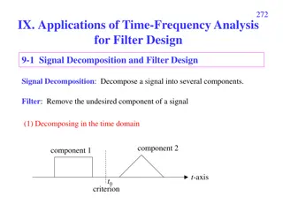
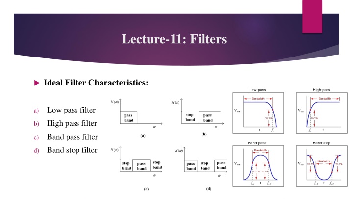
Lecture-11: Filters Ideal Filter Characteristics: Low pass filter a) High pass filter b) Band pass filter c) Band stop filter d)
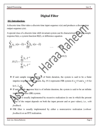
Chapter-7: Implementation of discrete-time system Finite Impulse Response (FIR) filters: The filters which have an impulse response containing only a finite number of values are commonly called finite impulse response(FIR) filters. Structure For Finite Impulse Response (FIR) Systems: Direct-form structure 1. Cascade-form structure 2.
Direct-Form Structure of FIR Filters The direct-form realization follows from the convolution summation: ? 1 ? ?(? ?) ? ? = ?=0 The structure is illustrated below: Figure: Direct-form realization of FIR system
Here, the structure requires L-1 memory locations for storing the L-1 previous inputs and has a complexity of L multiplications and L-1 additions per output point. Since the output consists of a weighted linear combination of L-1 past values of the input and weighted current value of the input, the structure resembles a tapped delay line or a transversal system. So, the direct-form realization is often called a transversal or tapped-delay-line filter.
Cascade-form structure of FIR system The cascade realization follows naturally from the system function, H(z)= ?=0 It is a simple matter to factor H(z) into second order FIR systems so that, H(z)= ?=1 Hk(z) Where, Hk(z)= bk0+ bk1 ? 1+bk2? 2 ? 1bk? ? ?
Infinite Impulse Response (IIR) Infinite Impulse Response (FIR) filters: The filters which have an impulse response of infinite length are called infinite impulse response(IIR) filters. Structure For Infinite Impulse Response (IIR) Systems: Direct-form structure 1. Cascade-form structure 2.


")