Importance of grounding in ePIC focusing on safety, noise reduction, signal integrity, and related topics such as power distribution, shielding, and standards. Details guidelines, plans, and standards discussed in the ePIC Collaboration Meeting in January 2025.
Please find below an Image/Link to download the presentation.
The content on the website is provided AS IS for your information and personal use only. It may not be sold, licensed, or shared on other websites without obtaining consent from the author. If you encounter any issues during the download, it is possible that the publisher has removed the file from their server.
You are allowed to download the files provided on this website for personal or commercial use, subject to the condition that they are used lawfully. All files are the property of their respective owners.
The content on the website is provided AS IS for your information and personal use only. It may not be sold, licensed, or shared on other websites without obtaining consent from the author.
E N D
Presentation Transcript
Grounding Considerations in ePIC Fernando Barbosa, Tim Camarda Integration Session 2 ePIC Collaboration Meeting 20-24 January 2025
Outline Introduction Guidelines Standards IP6 ePIC Collaboration Meeting, 20-24 January 2025 F. Barbosa, T. Camarda 2
Introduction The importance of grounding most often considers: Safety Low Noise Good Signal Integrity A reference potential = Earth ground. Other topics associated with grounding also include: Power Distribution Shielding Wiring Cabling Standards. ePIC Collaboration Meeting, 20-24 January 2025 F. Barbosa, T. Camarda 3
A plan for grounding in ePIC to establish the rules to be adhere to by all sub-detectors and to apply to all equipment installed in support of ePIC and to include detailed and specific information: Electrical Schematics Mechanical drawings Standards QA/QC Management plan for installation and operations. To be completed in 2025 and included in the TDR. ePIC will benefit from the grounding infrastructure from STAR and already in IP6. ePIC Collaboration Meeting, 20-24 January 2025 F. Barbosa, T. Camarda 4
Guidelines AC power segregated into Clean and Conventional. Grounds segregated into Clean and Conventional/Facility. Clean for sensitive detector electronics only. Floating Power Supplies: Referenced to clean GND at the detector for low noise and good signal integrity plus ground fault monitor. Grounding & Shielding Builds upon the STAR installation in IP6. GND wiring to be insulated, Green or Green/Yellow. 16 AWG or 10 AWG straps within sub-detector or larger 4 AWG from sub-detector to Clean GND. HV Supply I Signal i LV Supply I HV + - - Filter LV + - + r Regulator r Low Z Signal returns! Magnet GND = Clean GND 8x 4/0 AWG, insulated, green Strive for low impedance connections/bonding. All conductive surfaces to be bonded. Grounding Pillar Earth Reference ePIC Collaboration Meeting, 20-24 January 2025 F. Barbosa, T. Camarda 5
Keep detectors independent, grounding separate until connection to low Z ground common reference to minimize any possible effects among sub-detectors. Ensure isolation of detector and its electronics from any other structure or system minimize capacitive coupling to: Beam pipe Mechanical supports Pipes Magnet utilities. Earth Reference Minimize impedance Zc (low R, L) with multiple wires (e.g. 8x 4/0 AWG). ePIC Collaboration Meeting, 20-24 January 2025 F. Barbosa, T. Camarda 6
Standards Cabling NEC 2021 NFPA 70, UL CL2 or better. NEW BNL Document: EIC-SEG-STD-002 Cable Routing NECA/NEMA 105-2007. Open cable tray systems. EMI & RFI FCC part 15, Class B, CISPR 11/EN55011 Class B, CISPR 22/EN 55022 Class B and EN 61000-6- 3, or equivalent. NOTE: Exceptions or non-conformance to these standards must be approved prior to installation. QA/QC ESH&Q EMI surveys to be conducted during the installation phase and recommended during the design phase. Equipment that is NOT certified by a Nationally Recognized Test Lab (NRTL), such as UL and recognized by OSHA, be registered, processed and approved by BNL and/or Jlab prior to installation. ePIC Collaboration Meeting, 20-24 January 2025 F. Barbosa, T. Camarda 7
IP6 On-Detector, Off-Detector Pole-Tip & Beam-line Detector Power & Ground Overview W. pole-tip electronics (BKWD-HCAL) powered from S. Platform N. Service Platform Facility power dirty ground ASSEMBLY HALL Ground pillar location Far-forward (Beam-Line) detectors (Roman pots & ZDC) powered from isolation transformers inside of tunnel. Cooling & pump systems installed here & powered by facility ground. Note: conductive plumbing must be electrically isolated. S. Platform electronics racks bonded to magnet ground. E. pole-tip electronics ( HCAL & EM-CAL) powered from S. Platform breaker panels Power is delivered by 2x 225KVA Delta-Wye transformers mounted on N. Platforms Electrically isolated magnet carriage ePIC Collaboration Meeting, 20-24 January 2025 F. Barbosa, T. Camarda 8
IP6 Detector & Magnet Ground Isolation From Facility Power (On-Magnet & Pole-tip Detectors) 225KVA Delta/ Wye Isolation transformers on N. Platform, Feeds S. Platform Detector Electronics To off-platform electronics at Pole-Tips 60 AMP Breaker Panel 208V Location: S. Platform 480VAC Facility Power From DAQ room GROUND FAULT MONITOR 3 208 / 120 VAC 60 AMP Service to racks Power cables from N. Platform To South Platform breaker panels 1 bonding rod welded to pillar & grounding plate GROUNDING PILLAR ISOLATED CLEAN MAGNET GROUND RETURN ASSEMBLY HALL FACILITY GROUND FEB ELECTRONICS 208V/120V Ethernet PDU INSTALLED AT DETECTOR SIDE & OFF- DETECTOR AT POLE-TIPS Grounding plate Single point connection for magnet ground Magnet flux return steel Bonded to isolated ground 120/ 208VAC ------------- Current Transducer PN: 4688 Floating LV supply LV POWER CABLES TO DETECTOR ELECTRONICS DETECTOR 0000-AWG GROUNDING CABLES x 8 Bias & HV POWER CABLES TO DETECTOR ELECTRONICS SHIELDS CONNECTED AT SOURCE END N ------------- Floating Bias supply 500Hz AC Current regulated ground monitor PSU L G Power supply returns are tied to magnet ground only at detector side electronics ISOLATED CARRIAGE Bolted to pillar Magnet Ground Bonding plate 19 Equipment Cabinet ASSEMBLY HALL Ground strap from magnet to platform racks & equipment South Electronics Platform Upper & Lower Levels WAH Ground Rod ePIC Collaboration Meeting, 20-24 January 2025 F. Barbosa, T. Camarda 9
IP6 Assembly Hall Grounding Pillar (Single Point Ground for ePIC Magnet) Bonding Point Ground Rod Fig.1 Magnet single point ground bonding plate 8x 0000AWG Cables Located in Assembly Hall Fig.3 Grounding Pillar Bonding & Ground Rod to Earth Fig.2 Magnet ground pillar in Assembly Hall ePIC Collaboration Meeting, 20-24 January 2025 F. Barbosa, T. Camarda 10
DC & AC coupled (capacitance) leakage monitoring & testing ICAP = IPP * sin( t + 90 ) To measure the both AC & DC coupled leakage current caused by materials close to the detector (fig.1), a single- phase AC power source is injected from the grounding pillar to the magnet (fig.2). AC Leakage Current Resistive & AC Coupled Leakage Ground return path from magnet to grounding cables measured at pillar AC coupled noise will then bee seen as an impedance change where the imbalance will be indicated as leakage current. Fig.1 STAR experiment at IP6 grounding scheme for reference The imbalance in the Line & Neutral of the power source is measured by the current transducer that is mounted to the grounding pillar (fig.3). Below is the proposed AC source from Instek. Readback by monitor Leakage imbalance reported by transducer is sent to a custom readout box transmitted over TCP/IP ILEAKAGE =( ISET IMONITOR) If leakage current increases, then IMONITOR decreases & falls below a trip threshold Fig.2 8x 0000AWG Ground return cables from magnet to single point ground bonding plate. Grounding pillar in assembly hall Current transducer goes here 45Hz to 999.9Hz Fig 2. plate to pillar bonding rod used for current sensor ePIC Collaboration Meeting, 20-24 January 2025 F. Barbosa, T. Camarda 11
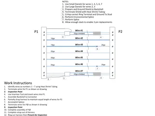
Remote Instrumentation Crate Grounding & Ground Noise 3 Isolated 208VAC from S. Platform Fig.1 STAR Forward calorimeter FEB to Remote Digitizer LV PWR & Signal Diagram 208V/120V Ethernet PDU Fig.3 Common Mode Noise measured from Diff. signals [1] to detector ground [3] (140mV pp) 4us/div Fig.2 Baseline noise measurement at Detector Ground [3] (65mV pp) 2us/div 60 Shielded 16 channel differential signal cable 208VAC to crate Interconnect Pannel 1 Waveform Digitizer Crate Multichannel FEB Differential out 2 DEP 32 Shield terminated on detector side magnet ground . Differential signal pairs 3 LV PS return Tied to magnet ground at detector side Wiener MPOD LV Crate 5VDC Floating + - 60 LV Power Cable FORWARD CALORIMETERS Mounted off Detector Differential noise measured at digitizer input [1] is only ~ 50mV pp Cabinet Ground Common mode noise is handled by the CMRR of the input circuit 4 However, Input receivers or front-end amplifiers need headroom (CMVINPUT range) to accommodate p-p common-mode noise Crates are bonded to cabinet ground for safety Fig.4 Common Mode Noise at Equipment Rack Measured from crate ground [4] to Ground [2] (300mV pp) 10ms/ div ePIC Collaboration Meeting, 20-24 January 2025 F. Barbosa, T. Camarda 12


 leakage monitoring")