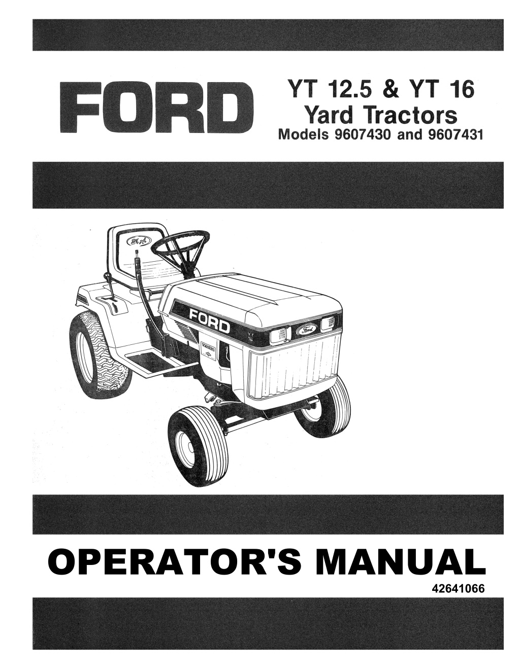
Ford YT12.5 & YT16 Yard Tractors Operator’s Manual Instant Download (Publication No.42641066)
Please open the website below to get the complete manualnn//
Download Presentation

Please find below an Image/Link to download the presentation.
The content on the website is provided AS IS for your information and personal use only. It may not be sold, licensed, or shared on other websites without obtaining consent from the author. Download presentation by click this link. If you encounter any issues during the download, it is possible that the publisher has removed the file from their server.
E N D
Presentation Transcript
OPERATOR'S MANUAL 42641066
INTRODUCTION This operator's manual has been prepareq to provide the information you need to correctly assemble, operate and maintain your unit. Read it carefully and keep it for future reference. Should you ever need repair parts or service, con- tact your authorized parts and service dealer. NOTICE: A decal with the product model number and serial number of your unit is on the left side of the tractor fral"'" engine base assembly. Record these numbers in the spc provided below. Engine model, type and code numbers u . ~ located on the engine blower housing, cylinder head shield or backplate. . Be sure safety precautions are observed. Read and follow all safety and operating instructions in this operator's manual. Product Model No. ______________ _ Any references made in this manual concerning the right- or left-hand sides are determined with the operator facing for- ward in the operating position. Product Serial No. Engine Model No. Engine Type No. The replacement of any part on this product by other than the manufacturer's authorized replacement part may adversely affect the performance, durability or safety of this product. Engine Code No. Dealer Purchased From ____ _______ __ _ Date Purchased The manufacturer reserves the right to make changes on, or add improvements to its product at any time without prior notice or obligation. The manufacturer also reserves the right to decide, upon its descretion and at any time, to discontinue a product. Dealer Address Dealer Telephone No. C1069
TABLE OF CONTENTS Brake Pad. Steering Gear. Electric PTG. Clutch ....... . . . . 6 Electrical System Battery-Electrolyte Level . Cleaning The Battery . . . . . . . . Battery-Jump Starting. Fuse. Safety Interlock System .. .. . . . . . .. .... . .. . 6.1 7 Storage ..... 8 Trouble Shooting .... .. .... . .. . . . . 9 Wiring Diagrams 16 HP. Units .......... .. . . .. .. ..... . ... ... 9.1 12.5 HP. Units . . . . . . . . . . . . . . . . 10 Set-Up And Assembly Hardware Bag Contents .. ... ........ .. .. 10.1 Battery ....... ............ .... . . . , .. 10.2-10.3 Steering Wheel ... , . . . , , , , , . . , .. . . . , ... , . 10.3 Seat .. ...... .... ............... . . . , .... , 10,4 Initial Servicing, . , . , .. , . , , , , . , , . . , , ..... . 10.5 11 Replacement Decals Safety . . . . . . . . . . . . . . . . . . . . . . . . . . . . . 11.1 Standard .... .. . ... ... .. , ....... . , , .. ... 11.2 12 Optional Accessories , , , . , . , . . , .... ... , .. . 12.1 13 Engine Information 14 Owner Assistance . 1.1-1.2 1 Safety Precautions ..... . Controls And Operation Control Locations. . Brake Clutch Pedal. . . Gear Shift Lever. . . . . .. ...... ... Attachment Lift Lever. . Parking Brake Latch. . . Choke Control. . . . . . . . . . . . . . . . . . . . . . . .. . . 2.3 Engine Speed Control. . . . . . . . . Manual PTa. (Power Take-Oft) Lever. . Electric PTG. (Power Take-Oft) Switch . .. .. . . 2.3 P.T.o. Warning Light. . . . . . Headlight Switch. . . . . . . . . Ignition Switch. . . . . . . . . . . Seat Adjustment ...... ...... .. ...... ...... 2.3 Ammeter ...... . . ... . ... . .... ....... ...... 2.3 3 Trial Run ........ .... .. ............... .... ... 3.1 4 Maintenance And Lubrication Break-In Maintenance And Lubrication .. ... 4.1 Daily Schedule ............. .. .. .... ... . . . . 4.1 25 Hour Schedule .... . .. . . . . ... ... .. ...... 4.2 100 Hour Schedule ... ... ..... . .. .... .. . ... 4.2 5 Adjustment And Servicing Rear Fender Seat Pan Removal ............ 5.1 Gas Tank Removal ... .......... . . ...... . . . 5.2 Traction Belt ...... .. .. . ..... ....... . ...... 5.3 Belt Diagram ............. ... ... ...... . ... 5.4 Brake Clutch Pedal/Parking Brake .. .. .. .... 5.5 . .. ......... . . ..... . 5.5-5.6 . .. ..... .. . . . . . 5.6 . . 5.7 . 2.1 . . . 2.2 . 2.2 . .. . 2.2 . 6.1 . . 6.1 . . . 6.1 . . 6.1 . ..... . . .. ... .. . . 2.2 . 2.3 . . 2.3 . ... 7.1 .... 8.1 . 2.3 . . . ..... . . . ... 2.3 . ... .. . . ... 2.3 . ... . . . 9.2 IMPORTANT: If decals are missing, illegible, or damaged, they should be replaced. Notice to Customers in the State of California-The engine on this unit is NOT equipped with a spark arresting muffler. IMPORTANT USE OR OPERATION OF THIS ENGINE ON ANY FOREST COVERED, BRUSH COVERED, OR GRASS COVERED lAND WITHOUT A STATE APPROVED SPARK ARRESTER IN EFFECTIVE WORKING ORDER BY THE OPERATOR CONSTITUTES A VIOlATION OF THE lAW OF THE STATE OF CALIFORNIA, OTHER STATES MAY HAVE SIMIlAR lAWS. FEDERAL lAWS APPLY ON FEDERAL lANDS. C1070
https://www.ebooklibonline.com Hello dear friend! Thank you very much for reading. Enter the link into your browser. The full manual is available for immediate download. https://www.ebooklibonline.com
1 SAF-EfY PRECAUTIONS THE FOLLOWING PRECAUTIONS ARE SUGGESTED TO HELP PREVENT ACCIDENTS. A CAREFUL OPERATOR IS THE BEST OPERATOR. MOST ACCIDENTS CAN BE AVOIDED BY OBSERVING CERTAIN PRE; CAUTIONS. READ AND TAKE THE FOLLOWING PRECAUTIONS BEFORE OPERATING THIS TRACTOR TO HELP PREVENT ACCIDENTS. EQUIPMENT SHOULD BE OPERATED ONLY BY THOSE WHO ARE RESPONSIBLE AND INSTRUCTED TO DO SO. THE TRACTOR Know the controls and how to stop quickly. READ THIS OPERATOR'S !V1ANUAL and instructions fur- nished with attachments. DO NOT modify or alter or permit anyone else to modify or alter this tractor or any of its components or any tractor function. DO NOT ALLOW CHILDREN TO OPERATE THE VEHICLE. DO NOT allow adults to operate it without proper instruction. DO NOT CARRY PASSENGERS. DO NOT mow when children and others are around. There is no safe place for extra riders. Keep all shields in place. Replace safety and warning decals when they become illegible. FUEL USAGE SAFETY Handle gasoline with care. It is highly flammable. Only use approved gasoline container. DO NOT attempt to fill gas tank from fuel con- tainer unless the container spout or funnel fits inside the fuel tank filler neck.The use oftoo large a spout or funnel, or no funnel, may result in spilled gasoline, creating highly flammable gas vapors. This could result in fire and/or explosion, causing severe bodily injury. Never fill the gas tank indoors. NEVER take the cap off or refuel when the engine is running or hot; allow engine to cool for several minutes before refueling. DON'T SMOKE WHILE REFUELING OR ANYWHERE NEAR FUEL DO NOT store, spill or use gasoline near an open flame. When filling the tank, maintain control of the rozzle. DON'T nil fuel tank to capacity. Allow room for expansion. Wipe up any spills immediately. ALWAYS tighten the fuel tank cap securely. If the original equipment fuel tank cap is lost, ALWAYS replace it with an approved cap. A will-fit cap may not be safe. DON'T drive equipment near open fire. NEVER use gasoline for cleaning parts. TRACTOR OPERATION Disengage ail power to attachment(s), fully dep- ress brake-clutch pedal and shift into neutral before attempting to start the engine. Only use jumper cables in recommended man- ner as outlined in Operator's Manual. DO NOT bypass the safety interlock system. Con- sult your Dealer if your safety controls malfunction. Reduce speed and exercise extreme caution on slopes and in sharp turns to prevent tipping or loss of control. Be especially cautious when changing direction on slopes. Except for adjustment, DO NOT operate engine if air cleaner or cover directly over carburetor air intake is removed. Removal of such part could create a fire hazard. DO NOT operate without a muffler or tamper with the exhaust system. Damaged mufflers or spark. arresters CQuid create a fire hazard. Inspect periodically and replace if necessary. DO NOT operate the tractor engine in an en- closed building without adequate ventilation. Exhaust fumes can cause death. DO NOT start the engine or operate controls while standing beside the tractor. Always sit in the trac- tor seat when starting the engine or operating controls. DO NOT get off the tractor while it is in motion. Before leaving the operator's position, disenga power to attachment(s), lower the attachmenl ... , shift into neutral, set the parking brake and stop the engine and remove key (if so equipped). NEVER leave the unit when it is parked on an incline. Always park the unit on level ground where possible. If the unit is to be parked on an incline, always lower the attachment(s), set the parking brake, and securely block the wheels. To avoid up-sets drive the tractor with care and at . speeds compatible with safety, especially when operating over rough ground, crossing ditches. slopes and when turning. When using any attaChments, NEVER direct dis- charge of material toward bystanders nor allow anyone near the vehicle while in operation. Keep people and pets a safe distance away from machine. Disengage power to attachment (s) when trans- porting or not in use. Keep the tractor in the same gear when going downhill as used when going uphill. DO NOT, coast or free wheel down hills. Use care when pulling loads or using heavy equipment. a) Use only approved drawbar hitch points. b) Limit loads to those you can safely control c) Do not turn sharply. Use care when backir d) Use counterweight (s) or wheel weights Whbl I suggested in the Operator's Manual. 1.1 C1045
Watch out for traffic when crossing or near roadways. . lit is recommended that this machine not be used on public roads. However, if riding on public roads is unavoidable you must comply to equipment requirements per SAE J137b and/or ASAE S279.4 lighting and marking standard. These standards require vehicles be equipped with two (2) head- lights. one (1) red taillight. two (2) amber flashing warning lights and a slow moving vehicle (SMV) emblem for operation on public roods. MOWER OPERATION Clear the work area of objects which might be picked up and thrown. When using the vehicle with mower. proceed as follows: a) Mow only in daylight or in good artificallight. b) Never make a cutting height adjustment while the engine is running if the operator must dis- mount to do so. c) Check the blade mounting bolts for proper tightness at frequent intervals. d) Shut the engine off when removing the grass catcher or unclogging chute. Watch for holes. rocks and roots in the terrain and other hidden hazards. Keep away from drop-offs. DO NOT stop or start suddenly when going uphill or downhill. Mow up and down the face of steep . slopes; never across the face. .-I Disengage power to mower before backing up. DO NOT mow in reverse unless absolutely neces- sary and then only after careful observation of the entire area behind the mower. SERVICING, MAINTENANCE AND STORAGE Keep open flame away from battery or cold weather starting aids to prevent fires or explos- ions . Disengage power to attachment (s). stop the engine, disconnect spark plug wire (s)from spark plug (s) before cleaning and making any repairs or adjustments. DO NOT lubricate or make mechanical adjust- ments while the unit is in motion or when the engine is running. However, if minor engine adjustments must be made, set the parking brake. securely block the wheels and use extreme caution. It is necessary to adjust the carburetor with the engine running. Take extra care not to allow rings. wristwatches, clothing, etc. to become entangled with moving parts. DO NOT strike flywheel with a hard object or metal tool as this may cause flywheel to shatter during operation. causing personal injury or property damage. DO NOT change the engine govemor setting or over-speed the engine. To reduce fire hazard, keep the engine free of grass, leaves, or excessive grease. DO NOT clean while engine is running. Keep all nuts, bolts and screws tight to be sure the equipment is in safe working condition. NEVER store equipment with gasoline in the tank inside a building where fumes may reach and open flame or spark. Allow the engine to cool before storing in any enclosure. Keep the machine and supply of gasoline in loc- ked storage to prevent children or others from playing or tampering with them. When machine is to be stored for an extended time. disconnect battery cables or remove the battery. Under normal usage the grass catcher bag material is subject to deterioration and wear. Check bag frequently for deterioration and wear and replace worn bags. Check that replacement bags comply with the original manufacturer's recommendation or specifications. The vehicle and attachments should be stopped and inspected for damage after striking a foreign object and the damage should be repaired before restarting and operating the equipment. Keep the vehicle and attachments in good oper- ating condition and keep safety devices in place and in working conditon. SAFETY DEFINITIONS The signal word "WARNING" indicates that a source of danger to a person on or near a machine exists which may result in death or injury if the recommended precautions are not taken . The signal word "DANGER" signifies that a source of extreme danger to a person on or near a machine exists as a result of the very nature of the machine itself. This danger to persons is such that .. would result in a high likelihood of death or per- anent injury if the recomrnened precautions are . ottaken. When you see this symbol.t means: AITENTlON! BECGr.,IIE ALERT! YOUR SAFETY IS INVOLVED! 1.2 C1046
2 CONTROLS AND OPERATION Refer to Fig. 2.1A IMPORTANT: Be sure to read this section of the Operators Manual before your attempt to operate your tractor. It is for your safety that you know where all controls are and are familiar with the functions of each control. N Attachment Lift Lever z Choke Control Brake Clutch Pedal Y Tl064 PJ.o. Warning Light GEAR SHIFT PATTERN (ALL MODELS) Engine Speed Control ---'<>.nt Adjuster Handle RELEASED Position (Parking Brake Latch) ;-Attachment Lift Lever Brake Clutch Pedal Headlight Switch Choke Control Parking Brake Latch Gear Shift Lever YTI066 FOR UNITS EQUIPPED WITH MANUAL P.T.O. Engine Speed Control RELEASE Position (Parking Brake Latch) FIG.2.1A 2.1 C1071
BRAKE CLUTCH PEDAL PARKING BRAKE LATCH Depressing the brake clutch pedal applies the brake and at - hq same time disengages the drive. I operate: Depress brake clutch pedal fully for starting. braking and changing gears. Remove foot slowly and com- pletely from brake clutch pedal to engage drive. This latch is hand operated and sets the parking brake. The latch is located on the right-hand side of the frame above the footrest. TO SET: Depress brake clutch pedal completely and slide latch forward and up to SET position (see circled illustration Fig.2.1A). NOTE: The brake clutch pedal must be completely dep- ressed. and the PT.o. must be in the OFF position. before the engine can be started. TO RELEASE: Depress brake clutch pedal until latch releases. A WARNING: To avoid personal Injury, the parking .. brake should be set before the operator leaves the seat. GEAR SHIFT LEVER This lever controls the ground speed (5 speeds forward and 1 reverse). The tractor was designed to start out in any gear. The gear should be chosen to suit the terrain and the needs of the attachment being used. Change gears only with unit at full stop and brake clutch pedal fully depressed. IMPORTANT: To Avoid damaging transmission, never shift In motion. Always place gear shift lever in neutral N before starting engine (Fig. 2.1A). Fully depress brake clutch pedal. and then move shift lever to the desired gear position (1 or 5 for progressively faster forward movement. R for reverse). Slowly release brake clutch pedal to . 'iate tractor movement. Operate Mower Only In Lowered Pos"lon AnACHMENT LIFT LEVER To Lower , Refer to Fig. 2.2A Depress Button This control will raise or lower attachments (mowers. snow- throwers etc.). Be sure attachment has been properly mounted before using lift lever. To raise attachment. pull lever back until the lock engages itself. To lower attachment. pull lever back. depress button on top of lever with your thumb and push lever forward. NOTE: An optional electric lift is avaliable as an accessory from your dealer. It is recommended for attachments other than mower and front snow blade. A WARNING: To avoid personal InJury ,never operate .. mower with attachment 11ft lever In a transport posl- flon. Mower must be lowered completely before operating. DO NOT OPERATE MOWER WITH GUARDS REMOVED. Push Forward To Lower Pull Back To Raise FIG.2.2A 2.2 C1072
A WARNING: To avoid personal injury, the P.T.O . .. should never be on unless an engine powered attachment is being operated. Place P.T.O. In off _ position when transporting an affachment to an' from a work area. CHOKE CONTROL This control aids in starting a cold engine. For cold engine starting pull knob outward. As the engine warms. push in. Choke is not required for restarting a warm engine. P.T.O. WARNING LIGHT-For Units With A Elec- tric P.T.O. ENGINE SPEED CONTROL Thiswarning lightwill go on when PJ.o.switch is intheON posi- tion, warning you that an attachment has power. This control regulates the engine speed from SLOW (idle) to FAST (maximum operating power and speed). The light will operate only if ignition key is in the ON position. Light will turn off if PJ.o, switch or ignition key is turned off. When starting engine. set control to a mid-range position. As engine warms up, gradually move control to maximum FAST position. IMPORTANT: Before starting tractor, check light. For your safety, keep warning light operating correctly. NOTE: Always use maximum FAST position when attachments are being used. HEADLIGHT SWITCH To idle, set control in SLOW position. This "rocker" type switch turns the lights ON and OFF. MANUAL P.T.O. (POWER TAKE-OFF) LEVER NOTE: The engine must be running for the lights to operate. (Dimming of lights when engine is idling is normal). This control engages and disengages power to the attach- ments. IGNITION SWITCH NOTE: The PJ.o. must be in the OFF position and brake clutch pedal must be completely depressed before the engine can be started. A WARNING: To avoid personal Injury ,before engag .. Ing the P.T.O., be sure the aHachment Is clear of any obstacles. For satety purposes a key type ignition switch is utilized for start- ing and instantly stopping the engine. TO START: Turn and hold key at START position until engine is running; then release key. Turn key to OFF position to stop engine. SEAT ADJUSTMENT To ENGAGE, move lever to ON position. To DISENGAGE, move lever to the OFF position. FOR UNITS EQUIPPED WITH A SEAT ADJUSTER HANDLE. WARNING: To avol. d personal injury, the P.T.O. should never be ON unless an engine powered attachment is being operated. Place P.T.O.ln OFF when position transporting an aHachment to and from a work area. TO ADJUST: Sit in tractor seat; pull seat adjuster handle up to release lock, then slide seat forward or backward to desired position. Release handle to secure adjustement. FOR UNITS NOT EQUIPPED WITH A SEAT ADJUSTER HANDLE ELECTRIC P.T.O. (POWERTAKE-oFF) SWITCH TO ADJUST: Loosen the two knobs at the rear of the seat sup- port. Slide the seat support to the desired position and re- tighten both knobs securely. This switch controls the drive to engine powered attach- ments. AMMETER-For Units So Equipped NOTE: The P J.o. must be in the OFF position and brake clutch pedal must be completely depressed before the engine can be started. A WARNING: To avoid personal Injury ,before engag .. Ing the P.T.O., be sure the aHachment Is clear of any obstacles. The ammerter indicates whether battery is charging or dis- charging. Movement of ammeter needle to the right of center indicates battery is charging; movement to the left of center indicates battery is discharging. Normal operation of the tractor will keep the battery fully charged. NOTE: If ammeter does not move, or indicates constant discharging, contact your au- thorized dealer for service instructions. To ENGAGE, pull toggle lever out then up to the ON position. To DISENGAGE, pull toggle lever out and then down to the OFF position. 2.3 C1073
3 TRIAL RUN ''I.Iow that you have located the controls and understand their )peration and function it is time to test ride your new tractor. Do this without operating on attachment until you have the feel of the unit. A WARNING: To avoid personal Injury, give complete .. and undivided attention to safe operation ot the tractor. Remember, improper use of the tractor Is hazardous. A WARNING: To avoid personal Injury trom overturns, .. do not use wheel weights, a weight box, or any additional weights for stability when operating trac- tor on hills. BEFORE STOPPING ENGINE 1. Move shift lever to neutral N. 2. Disengage PTO 3. SET the parking brake TO STOP ENGINE Turn ignition key to OFF. Remove key (For increased traction use only authorized wheel weights.) This tractor is equipped with an interlock system which will allow the engine to start only if the brake clutch pedal is fully depressed, the P.T.o. is in the OFF position and the operator is properly seated. BEFORE STARTING 1. Be certain that the engine crankcase Is filled with 011 and the engine service instructions have been followed completely. 2. Sit on the tractor seat in the normal operating position. Refer to seat adjustment procedure. 3. Place shift lever in NEUTRAL position. 4. Move P.T.o. to OFF position. 5. Set engine speed control in mid-position between SLOW and FAST. 6. Pull choke outward if starting a cold engine. Choke might not be required for worm engine starting. 7. Fully depress broke clutch peda\. TO START 1. Turn ignition key to START until the engine starts then release the key. Do not engage starter for more than a 10 second duration. Wait 60 seconds, then engage starter for another 10 seconds or until engine storts. This will prolong starter life. 2. As the engine warms up push choke in and move engine speed control to FAST. TO OPERATE Start out in 1'stgear"1". TO CHANGE SPEED, fully depress brake clutch pedal and move lever to desired position. Remove foot slowly and completely from pedal to engage drive. Do not shift In motion. Try all gear positions. A .y#ARNING: To avoid personal Injury, use . a slow ... speed until you leamhow to drive the tractor. 3.1 C1074
4 MAINTENANCE AND LUBRICATION WARNING: To avoid personal Injury, always turn engine off and waH for all movemenfto stop. Remove spark plug wlre(s) from spark plug(s) before clean- ing, making any repairs or adjustments. 6. OPERATING LIGHTS: Check operation of all lights before starting and using your tractor. NOTE: To check operation of headlights, engine must be running. IMPORTANT: If lights do not work, check circuit and correct failure before starting or using the tractor again, Refer to the WIRING DIAGRAM section. BREAK-IN MAINTENANCE AND LUBRICATION NOTE: If lights need replacement, order replacement parts from your authorized dealer. IMPORTANT: Apply oil and grease carefully and only where required. Oil or grease on drive belts or pulleys will cause slip- page and loss of drive. Thoroughly wipe up any excess grease, oil and spills. 7. BELTS: Inspectfor proper tension . Refer to ADJUSTMENT AND SERVICING section. For maximum efficiency and trouble free service, make the following periodic inspections of the tractor. For engine main- tenance, refer to the engine instructions. 1. The engine oil should be changed as described in the engine instructions. The oil drain pipe is located on the right-hand side of engine just above frame. A. WARNING: To avoid personal Injury from severe ... bums, use care when draining 011. Engine and 011 ore extremely hot. Do Not come In contact with engine or 011. Place an oil pan under drain and remove oil drain cap. The best time to change ollis just after the engine has been run. Use cardboard or tinfoil to form a gutter from the drain to the oil pan. After the oil has been drained, replace the oil drain cap. Remove the oil fill cap and dipstick. For proper type of oil and crankcase capacity refer to the engine instructions. Do not overfill. When checking oil level, scrf!!W dipstick assembly firmly but slowly until cap bottoms on tUbe. Dipstick assembly must be securely assembled into tube at all times when engine is operating. 2. Perform all other checks and maintenance called for under "Daily", "25 Hour", and "100 Hour" schedules, DAILY SCHEDULE 1. GENERAL: Make general visual inspection of the tractor for loose or damaged parts. Check nuts and bolts periodically to insure against looseness caused by vibration or rough handling. Check for oil leaks from engine and transaxle, Damaged parts should be repaired or replaced before using the tractor. 2. ENGINE OIL LEVEL: Refer to the engine instructions. Check oil level with tractor on level ground and the engine stopped. Before removing dipstick, clean dirt from aroul1d dipstick and opening. 3. ROTATING SCREEN: Inspect rotating screen for chaff or dirt build-up and clean as r e q u i ~ ~ ( F i g . 4.2A). 4. AIR CLEANER: Refer to the engine instructions for proper ". mainterlance. . 5.' 6ATTERY T erminals. should ~ t i g h t and fr }'8 Of corrosion. The hold down should e snug:f'over battery Top of battery sho\.Jld beclean and dry Ctleck leVelof.electrc>lyte. Main- tain electrolyte level up to lhe bottom of venfwells;Add cleon di$tilledwdt,er as needed.. 4.1 C1OS1
25 HOUR SCHEDULE IGENERAL: Perform the "Daily" maintenance schedule. 1. 2. ENGINE OIL: Refer to the engine instructions. 3. AIR CLEANER: Refer to the engine instructions. 4. GREASE: Use NLGI Grade 2 Lithium base EP grease or quivalent. NOTE: Clean off grease fittings before attach- ing grease gun. Grease until the grease comes out of bearings. Wipe off excess grease. Use a pressure type grease gun. Refer to Fig. 4.213. A. Front \lVheels: one fitting located on inner side of each wheel. B. TIe Bar: one fitting on each end. C. Spindles: one fitting on each end of front axle. D. Axle Pivot: one fitting in center of axle . FIG.4.2A 5. OIL: SA.E 30 engine oil. General - Apply oil to all pivot points and linkages to reduce wear and assure free movement. Be sure linkages are clean before applying oil. 6. TIRE PRESSURE: Check tire pressures. Recommeded pres- sure is 1 Op.s.i. for both front and rear tires. Under inflated tires will cause premature failure. Over inflated tires will result in a hard riding tractor which may also loosen hardware on the unit. Grease Fitting (Spindle) 100 HOUR SCHEDULE 1. GENERAL: Perform the "25 Hour" maintenance schedule. 2. For all engine maintenance refer to the engine instruc- tions. 3. TRANSl\XLE: The transaxle is filled for life and should not require additional lubrication. Make periodic visual inspec- tions of transaxle. If damage or leakage occurs, contact your authorized dealer for seNice or repair. Grease Fitting (Axle Pivot) 4. BATTERY: Wipe the outside of battery clean with soap and water. Clean off corroded battery terminals with baking soda or steel wool. Tighten cables securely to battery ter- minals. Apply a light coat of petroleum jelly or chassis lube to avoid corrosion. Check battery hold down; tighten if needed. Keep vent holes in battery filler caps open. Re- move caps and inspect, Ifthe holes are clogged, clean out using a small piece of wire. Do not blowout. Replace caps. FIG.4.2B 5. BODY CARE: The best way to preserve the paint finish on your tractor is to keep it cleanwith frequent washings. Wash the tractor with either warm (Never Hot) or cold water. Do not wash your tractor in the direct rays of the sun, and not while the sheet metal surfaces are hot. Never wipe dirt from a dry painted surface, as thismav scratch the finish. Polishing your trador with d paste wax will provide an added degree of protection against tar, oil. tree sap and other foreign matter. 4.2 C1075
5 ADJUSTMENT AND SERVICING WARNING: To avoid personal injury, always turn engine off and wait for all movement 10 stop. Re- move spark plug wire(s) from spark plug(s) before cleaning, making any repairs or adjustments. REAR FENDER SEAT PAN REMOVAL. . IMPORTANT WHEN REMOVING REAR FENDER SEAT PAN AND GAS TANK REFER TO OPERATOR'S MANUAL FOR INSTRUCTION. FIG. S.1A (2) Large Nylon Washers (Lever Adjustable Seat Only) (1) Large Nylon Washer (Knob Adjustable Seat Only) Spacer 1 Tip the seatforward a nd locate the two seat switches under the seat and disconnect plug from each seat switch (Fig. 5.1A). 2. Remove plastic connector and gently pull the wires through the hole in the side of the seat hinge support (Fig. 5.1A). NOTE: Some models may have a large grommet in fender pan and will not require removal of connector. Rear Fender Seat Pan NOTE: If your tractor has taillights the wires must be discon- nected from each taillight. !i---Seat Hinge Support 3.Remove the hinge pin. Remove the hardware from one side only and remove pin (Fig. 5.1A). (2) Large Nylon Washers (Lever Adjustable Seat Only) (1) Large Nylon Washer (Knob Adjustable Seat Only) 4. Remove the seat hinge support from the rear fender seat pan (Fig. 5.1B). Remove all four cap screws, spacers and washers. Some models will have two cap screws and two knobs. 5. Remove the two screws holding the rear fender seat pan to the support (Fig. 5.1C). FIG. 5.11 6. Remove the two carriage bolts mounting the rear fender seat pan to the footrest (Fig. 5.1C). Repeat for the other footrest. Remove These Screws 7. Remove knob from the gear shift lever if so equipped. 8. Remove the gas cap from the gas tank and lift the rear fen- der seat pan off of tractor. 9. Replace gas cap to avoid spilling gas and to prevent foreign debris from entering tank. ~ ' : ' l " : ~ ~ " : : : : : : : ; = - - R e m o v e These Carriage Bolts YTAI173 FIG.5.1C 5.1 C1076
Suggest: If the above button click is invalid. Please download this document first, and then click the above link to download the complete manual. Thank you so much for reading
GAS TANK REMOVAL WARNING: To avoid personal injury, use extreme A care when handling gasoline .. Drain gasoline into a clean, light container approved for gasoline sto- rage. Keep all flames, sparks and lit Cigarettes away from gasoline. Clean up any spills immedi- ately. ~ NOTE: If the gas tank does not have to be removed it can be tipped out of the way by following steps 1 & 2. TAIIOO 1. Remove the two screws on each side of the support (Fig. 5.28). Carefully slide the support toward the front of tractor. 2. After support is out of the way, tip gas tank up to gain clearance. NOTE: If gas tank has to be removed follow the remaining instructions for proper removal of gas tank. 3. Remove clamp holding gas line (from gas tank) to filter at the engine (Fig. 5.2A). 4. Remove gas line from filter and drain into container (Fig. 5.2A). Gas Line - (Tank To Filter) Use This Line To Drain Gas Tank ...... - IMPORTANT: When gas line is removed a small amount of gasoline will run out of filter. Wipe up spills immediately. 5. Drain all gasoline from gas tank. The capacity of the gas tank is approximately 3112 gals. FIG. S.2A NOTE: Refer to the ADJUSTMENT AND SERVICING section ("Rear Fender Seat Pan Removal") before removing gas tank. Gas Tank - Pull ~ c t AAd Tip Up ~ 6. Gently pull the gas tank straight back until the front edge of gas tank clears the back edge of the support (Fig. 5.28). Be careful not to pull gas line out of mounting clip at front of tractor. 7. Tip the front of gas tank up past the top oftractor frame and remove the clamp holding the gas line to the tank. Re- move the gas line from the tank (Fig. 5.28). 8. Remove the gas tank completely from the tractor. 9. Reverse the above procedure when reassembling. IMPORTANT: When reassembling the spacers to the rear fen- der seat pan be sure the spacer goes through the two large nylon washers completely. The spacer must rest against the rear fender seat pan (Fig. 5.1B Circled Illustration). Remove This Clamp IMPORTANT: To avoid damage to the gas line check to make sure gas line is not pinched or contacting any moving parts. Be sure both ends of the g. as line are fastened securely and the clamps are properly positioned. Remove These 'Screws On Both Sides To Remove Support NOTE,: Gently pull excess g(']s I i ~ e t()lNard f r o assembling gas.line to filter. Be sure gas line is securelyfas- tened on both ends (tank & filter). ,~ t o f tractor when
https://www.ebooklibonline.com Hello dear friend! Thank you very much for reading. Enter the link into your browser. The full manual is available for immediate download. https://www.ebooklibonline.com


