Flame Pyrolysis: Particle Formation and Growth Mechanisms
Understanding the intricacies of flame pyrolysis for particle formation and growth involving gas phase chemical reactions, coagulation, sintering, and surface growth processes. The method explores the effects of different reactants, temperatures, nozzle quenching, and electric field control on particle size and morphology. Advantages and disadvantages of flame pyrolysis in nanoparticle synthesis are also discussed.
Download Presentation

Please find below an Image/Link to download the presentation.
The content on the website is provided AS IS for your information and personal use only. It may not be sold, licensed, or shared on other websites without obtaining consent from the author.If you encounter any issues during the download, it is possible that the publisher has removed the file from their server.
You are allowed to download the files provided on this website for personal or commercial use, subject to the condition that they are used lawfully. All files are the property of their respective owners.
The content on the website is provided AS IS for your information and personal use only. It may not be sold, licensed, or shared on other websites without obtaining consent from the author.
E N D
Presentation Transcript
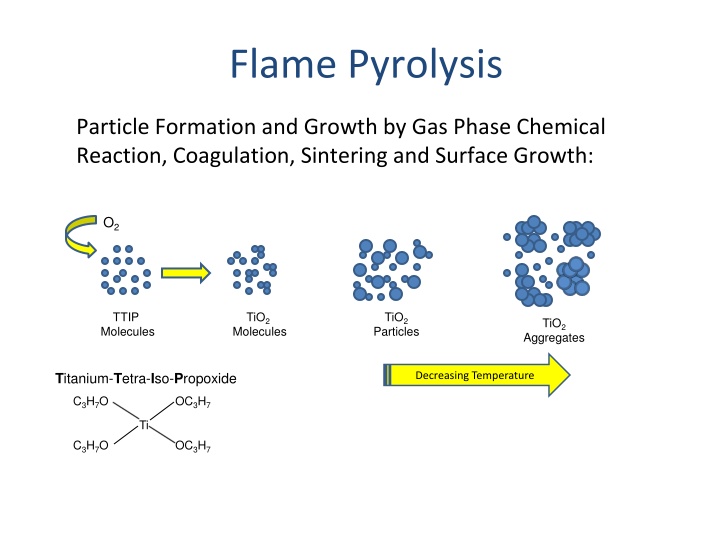
Flame Pyrolysis Particle Formation and Growth by Gas Phase Chemical Reaction, Coagulation, Sintering and Surface Growth: O2 TTIP Molecules TiO2 TiO2 Particles TiO2 Molecules Aggregates Titanium-Tetra-Iso-Propoxide Decreasing Temperature C3H7O OC3H7 Ti C3H7O OC3H7
Flame Pyrolysis: Jet Design CH4 CH4 Air Air CH4 Air Air Air TiCl4 TiCl4 TiCl4 TiCl4
Flame Pyrolysis: Jet Design Effect of Oxidant Composition on TiO2Morphology: Flame mixing C Flame mixing B Oxidant CH4 CH4 Oxidant TiCl4 TiCl4
Flame Pyrolysis: Nozzle Quenching Desired Flame length is controlled by rapid quenching Prevents agglomeration by inhibiting growth processes in the early stages of growth. Provides precise control of particle size Vapor
Flame Pyrolysis: Nozzle Quenching Nozzle Quenching controls flame length and particle size.
Flame Pyrolysis: Nozzle Quenching TiO2Particle Size Control by Nozzle Quenching
Pyrolysis: Electrostatic Charging Particle size can also be controlled by generating an electric field across the flame. A large electric field (hundreds of kV/m) is generated between two plate electrodes situated on opposite sides of the flame. Similar to nozzle quenching, the electric field limits particle growth by reducing the residence time in the high temperature region of the flame. In addition, the electric field charges the particles. This results in electrostatic repulsion between newly formed particles, preventing coagulation. S. Vemury, S.E. Pratsinis, L. Kibbey, Electrically-controlled flame synthesis of nanophase TiO2, SiO2, and SnO2 powders. JMR, Vol. 12, 1031-1042. 1997.
Flame Pyrolysis: Advantages & Disadvantages Pyrolysis is a high yield method that can fulfill the strong demand for nanoparticles. Can be customized to produce unique nanoparticles. Broad distribution of particle sizes and morphology.
Spray Pyrolysis An aerosol process that atomize a solution and heats the droplets to produce solid particles. Simple and low cost for powder and thin film deposition process Applicable to large areas; No need of exotic or expensive precursors; No need of vacuum.
Spray Pyrolysis Metals (Cu, Ni, Co, ) and metal oxides powders Converting microsized liquid droplets of precursors or precursors mixture into solid particles trough heating Droplets evaporation solute condensation decomposition & reaction sintering e.g. silver particles made from Ag2CO3or AgNO3with NH4HCO3@ 400 C
Spray Pyrolysis The precursor must be dissolved in the liquid, but not react with it. The product must not dissolve in the liquid, and must not react with the liquid. There must be a large volume decrease for the reaction of precursor to product. Transport of the leaching agent in the liquid and the fugitive compounds formed must be sufficiently rapid.
Spray Pyrolysis Advantages Spherical morphology Narrow particle size distribution Easy preparation of powders with complex formation Relatively homogeneous composition Continuously production Reaction occurs at the microcapsule reactor (droplets)
Spray Pyrolysis limitations Technique is quite empirical, with a number of variables that can affect the final product: - solute concentration - atomization technique - temperature, temperature gradient - residence time in furnace - carrier gases
Spray Pyrolysis Nozzle to substrate distance Droplet size: relates to size of product Substrate temperature Solution concentration Solution flow rate Atomization rate affects scalability of the process Droplet velocity affects residence time with the furnaces and ultimately size particle
Spray Pyrolysis Messing et al. J. Am.Ceram.Soc 1993
Spray Pyrolysis Droplet to particles conversion process
Spray Pyrolysis Low temperature and high initial solute concentrations Dense particles (aggregates of nanocrystals) High temperature and high solvent evaporation rate Hallow particles Nanoparticle < 100 nm Dilute solutions and very small initial droplet size
Conventional vs Salt-assisted Spray Pyrolysis Conventional Salt-assisted
Electrospray Pyrolysis By applying a 3KV electric field to the liquid coming from a cylindrical tube, it becomes conic.
Spray Process https://www.youtube.com/watch?v=mmtXFlIQD9E
Spray Pyrolysis: nanofilm https://www.youtube.com/watch?v=eJbuY4HJFV0
Flame Spray Pyrolysis: nanofilm https://www.youtube.com/watch?v=pAYsH7xnV6s
Chemical Vapor Deposition Chemical vapor deposition (CVD) is a vacuum deposition method used to produce high quality, high-performance, solid materials from a gas precursor. Thermal decomposition : SiH4 (g) Si (s) + 2 H2 (g) 650 C Reduction : WF6 (g) + 3 H2 (g) <-> W(s) + 6 HF (g) 300 C Oxidation : SiH4 (g) + O2 (g) SiO2 (s) + 2 H2 (g) 450 C Compound formation : BF3 (g) + NH3 (g) BN (s) + 3 HF (g) 1100 C
Oxides preparation Various metal oxides can be prepared by the reaction of a volatile metal compound (often a chloride) with O2 or water vapor: MXn (g) + (n/4) O2 (g) MXn (g) + (n/2) H2O (g) MOn/2 (s) + n HX2 (g) MOn/2 (s) + (n/2) X2 (g) The water vapor can be directly introduced or obtain in the reaction chamber from a suitable reaction: 1) CO2 + H2 2) O2 + H2 H2O 3) CxHy + O2 CO2 + H2O CO + H2O 38
Chemical Vapor Deposition Ultrahigh vacuum CVD (UHVCVD) CVD at very low pressure, typically below 10 6 Pa ( 10 8 torr). Low-pressure CVD (LPCVD) CVD at sub-atmospheric pressures. Reduced pressures tend to reduce unwanted gas-phase reactions and improve product uniformity. Atmospheric pressure CVD (APCVD) CVD at atmospheric pressure.
LPCVD https://www.coursera.org/lecture/nanotechnology/chemical- vapor-deposition-process-demonstration-EWSQl
CVD Classification by type of substrate heating Hot wall CVD CVD in which the chamber is heated by an external power source and the substrate is heated by radiation from the heated chamber walls. Cold wall CVD CVD in which only the substrate is directly heated either by induction or by passing current through the substrate itself or a heater in contact with the substrate. The chamber walls are at room temperature.
CVD and Plasma methods Plasma is a state of matter in which an ionized gases becomes highly electrically conductive to the point that long-range electric and magnetic fields dominate the behavior of the matter. Plasma Enhanced CVD (PECVD) CVD that utilizes plasma to enhance chemical reaction rates of the precursors. PECVD processing allows deposition at lower temperatures, which is often critical in the manufacture of semiconductors. The lower temperatures also allow for the deposition of organic coatings, such as plasma polymers, that have been used for nanoparticle surface functionalization.
Direct synthesis of graphene on silicon oxide by low temperature plasma enhanced chemical vapor deposition Nanoscale, 2018,10, 12779-12787
Dissociation MW Plasma
https://www.youtube.com/watch?v=n4hjudErUsQ http://www.chm.bris.ac.uk/pt/diamond/mwpecvd1.htm
N-V center defect consists of a nitrogen atom in place of a carbon atom next to a vacancy within the diamond s lattice structure. Nitrogen-vacancy Center: the blue atoms represent Carbon atoms, red atom represents Nitrogen atom substituting for a Carbon atom, and yellow atom represents a lattice vacancy
Nanodiamonds: inertness and hardness Skin care: Nanodiamonds are well-absorbed by human skin. They also absorb more of the ingredients in skin care products than skin itself. Thus they cause more of the ingredients to penetrate the deeper layers of the skin. Nanodiamonds also form strong bonds with water, helping to hydrate the skin. Micro-abrasive: Polishes and engine oil additives for lubrication. Catalysis: Support or metal free catalyst Medical: low cytotoxicity of diamond nanoparticles affirms their utilization as biologically compatible materials. Drug delivery. Sensors: electro- mechanical- system and response to magnetic field. Optical and Quantum computing: Single-defect nanodiamonds.
Remote Plasma-Enhanced CVD (RPECVD) Similar to PECVD except that the wafer substrate is not directly in the plasma discharge region. Removing the wafer from the plasma region allows processing temperatures down to room temperature.
