Evolution of Liquid Crystal Display (LCD) Technology & Applications
Liquid crystal displays (LCDs) have evolved from small screens in calculators to large, high-definition flat-panel TVs. LCD technology, discovered accidentally in 1888, utilizes liquid crystals that align to display images. Common LC phases include nematic, characterized by thread-like defects. LCDs are prevalent in electronics like mobile phones, cameras, and monitors due to their versatility and image quality.
Download Presentation

Please find below an Image/Link to download the presentation.
The content on the website is provided AS IS for your information and personal use only. It may not be sold, licensed, or shared on other websites without obtaining consent from the author.If you encounter any issues during the download, it is possible that the publisher has removed the file from their server.
You are allowed to download the files provided on this website for personal or commercial use, subject to the condition that they are used lawfully. All files are the property of their respective owners.
The content on the website is provided AS IS for your information and personal use only. It may not be sold, licensed, or shared on other websites without obtaining consent from the author.
E N D
Presentation Transcript
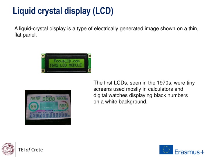
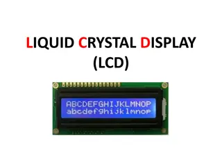
Liquid crystal display (LCD) A liquid-crystal display is a type of electrically generated image shown on a thin, flat panel. The first LCDs, seen in the 1970s, were tiny screens used mostly in calculators and digital watches displaying black numbers on a white background.
Liquid crystal display (LCD) Today, the latest LCD flat-panel TVs, which have largely replaced the traditional, bulky cathode-ray-tube kind, can produce high- definition colour images up to 108 inches on the diagonal. LCDs are now found everywhere in home- electronics systems, mobile phones, cameras and computer monitors, as well as watches and TVs.
Liquid crystal display (LCD) Liquid crystals were discovered by accident in 1888 by Austrian botanist Friedrich Reinitzer. He showed that a plant derivative, cholesteryl benzoate, had two melting points, becoming a cloudy liquid at 145 C and turning clear at 179 C. To seek an explanation, he passed his samples to physicist Otto Lehmann. Using a microscope fitted with a heating stage, Lehmann showed that the in- between cloudy state had optical properties typical of some crystals, et was a liquid and so the term liquid crystal was born.
One of the most common LC phases is the nematic. The word nematic comes from the Greek (Greek: nema), which means "thread". This term originates from the thread-like topological defects observed in nematics, which are formally called 'disclinations . Nematics also exhibit so-called "hedgehog" topological defects.
Some examples of substances that form liquid crystals are listed in the figure below Aromatic rings and multiple bonds between carbon and nitrogen or oxygen are especially common.
In a nematic phase, the calamitic or rod-shaped organic molecules have no positional order, but they self-align to have long-range directional order with their long axes roughly parallel. Thus, the molecules are free to flow and their center of mass positions are randomly distributed as in a liquid, but still maintain their long-range directional order. Most nematics are uniaxial: they have one axis that is longer and preferred, with the other two being equivalent (can be approximated as cylinders or rods). Nematics have fluidity similar to that of ordinary (isotropic) liquids but they can be easily aligned by an external magnetic or electric field. Aligned nematics have the optical properties of uniaxial crystals and this makes them extremely useful in liquid-crystal displays (LCD). Scientists have discovered that electrons can unite to flow together in high magnetic fields, to create an "electronic nematic" form of matter.
Liquid crystals The liquid crystals that make LCDs possible are liquid crystals in the nematic phase, One feature of liquid crystals is that they're affected by electric current. A particular sort of nematic liquid crystal, called twisted nematics (TN), is naturally twisted. Applying an electric current to these liquid crystals will untwist them to varying degrees, depending on the current's voltage. LCDs use these liquid crystals because they react predictably to electric current in such a way as to control light passage.
Liquid crystals The orientation of the molecules in the nematic phase is based on the director. The director can be anything from a magnetic field to a surface that has microscopic grooves in it. In the nematic phase, liquid crystals can be further classified by the way molecules orient themselves in respect to one another.
Liquid crystal display (LCD) The combination of four facts makes LCDs possible: Light can be polarized. Liquid crystals can transmit and change polarized light. The structure of liquid crystals can be changed by electric current. There are transparent substances that can conduct electricity. An LCD is a device that uses these four facts in a surprising way.
Liquid crystal display (LCD) To create an LCD, you take two pieces of polarized glass. A special polymer that creates microscopic grooves in the surface is rubbed on the side of the glass that does not have the polarizing film on it. The grooves must be in the same direction as the polarizing film. You then add a coating of nematic liquid crystals to one of the filters.
Liquid crystal display (LCD) The grooves will cause the first layer of molecules to align with the filter's orientation. Then add the second piece of glass with the polarizing film at a right angle to the first piece. Each successive layer of TN molecules will gradually twist until the uppermost layer is at a 90-degree angle to the bottom, matching the polarized glass filters.
Liquid crystal display (LCD) As light strikes the first filter, it is polarized. The molecules in each layer then guide the light they receive to the next layer. As the light passes through the liquid crystal layers, the molecules also change the light's plane of vibration to match their own angle. When the light reaches the far side of the liquid crystal substance, it vibrates at the same angle as the final layer of molecules. If the final layer is matched up with the second polarized glass filter, then the light will pass through.
Liquid crystal display (LCD) If we apply an electric charge to liquid crystal molecules, they untwist. When they straighten out, they change the angle of the light passing through them so that it no longer matches the angle of the top polarizing filter. Consequently, no light can pass through that area of the LCD, which makes that area darker than the surrounding areas.
Simple Liquid Crystal Displays There is a mirror (A) in back, which makes it reflective. Then, we add a piece of glass (B) with a polarizing film on the bottom side, and a common electrode plane (C) made of indium-tin oxide on top. A common electrode plane covers the entire area of the LCD. Above that is the layer of liquid crystal substance (D). Next comes another piece of glass (E) with an electrode in the shape of the rectangle on the bottom and, on top, another polarizing film (F), at a right angle to the first one.
The electrode is hooked up to a power source like a battery. When there is no current, light entering through the front of the LCD will simply hit the mirror and bounce right back out. But when the battery supplies current to the electrodes, the liquid crystals between the common-plane electrode and the electrode shaped like a rectangle untwist and block the light in that region from passing through. That makes the LCD show the rectangle as a black area.
Note that in this simple LCD required an external light source. Liquid crystal materials emit no light of their own. Small and inexpensive LCDs are often reflective, which means to display anything they must reflect light from external light sources. Look at an LCD watch: The numbers appear where small electrodes charge the liquid crystals and make the layers untwist so that light is not transmitting through the polarized film.
Electrodes are made of the transparent conductor Indium Tin Oxide (ITO). The liquid-crystal display is intrinsically a passive device, it is a simple light valve. The managing and control of the data to be displayed is performed by one or more circuits commonly denoted as LCD drivers Before an electric field is applied, the orientation of the liquid-crystal molecules is determined by the alignment at the surfaces of electrodes.
In a twisted nematic device (still the most common liquid-crystal device), the surface alignment directions at the two electrodes are perpendicular to each other, and so the molecules arrange themselves in a helical structure, or twist. This induces the rotation of the polarization of the incident light, and the device appears gray.
If the applied voltage is large enough, the liquid crystal molecules in the center of the layer are almost completely untwisted and the polarization of the incident light is not rotated as it passes through the liquid crystal layer. This light will then be mainly polarized perpendicular to the second filter, and thus be blocked and the pixel will appear black. By controlling the voltage applied across the liquid crystal layer in each pixel, light can be allowed to pass through in varying amounts thus constituting different levels of gray.
Most computer displays are lit with built-in fluorescent tubes above, beside and sometimes behind the LCD. A white diffusion panel behind the LCD redirects and scatters the light evenly to ensure a uniform display. On its way through filters, liquid crystal layers and electrode layers, a lot of this light is lost -- often more than half! In our example, we had a common electrode plane and a single electrode bar that controlled which liquid crystals responded to an electric charge. If you take the layer that contains the single electrode and add a few more, you can begin to build more sophisticated displays.
Passive-matrix LCDs Passive-matrix LCDs use a simple grid to supply the charge to a particular pixel on the display. The matrix is consisting of two glass layers called substrates. One substrate is given columns and the other is given rows made from a transparent conductive material. This is usually indium-tin oxide. The rows or columns are connected to integrated circuits that control when a charge is sent down a particular column or row.
The liquid crystal material is sandwiched between the two glass substrates, and a polarizing film is added to the outer side of each substrate. To turn on a pixel, the integrated circuit sends a charge down the correct column of one substrate and a ground activated on the correct row of the other. The row and column intersect at the designated pixel, and that delivers the voltage to untwist the liquid crystals at that pixel.
A passive pixel is addressed when there is a sufficient voltage across it to cause the liquid crystal molecules to align parallel to the electric field. A display can have more than one pixel on at any one time because of the response time of the liquid crystal material. When addressed, a pixel has a short turn-on time during which the liquid crystal molecules align in such a way as to make the pixel opaque. When the voltage is removed the pixel behaves similar to a discharging capacitor, slowly turning off as charge dissipates and the molecules return to their undeformed orientation.
Because of this response time, a display can scan across the matrix of pixels, turning on the appropriate ones to form an image. As long as the time to scan the entire matrix is shorter than the turn-off time, a multiple pixel image (like the animation below) can be displayed. The time scale of the animation has been stretched so as to see what is normally imperceptible to the human eye. The transparent electrodes momentarily revert to blue and red to signify voltage being applied. The pixel gradually becomes opaque. As the voltage is removed (as shown by the electrodes becoming colorless again) the cell remains opaque briefly before it becomes clear again.
Active-matrix LCDs Active-matrix LCDs depend on thin film transistors (TFT). Basically, TFTs are tiny switching transistors and capacitors. They are arranged in a matrix on a glass substrate. To address a particular pixel, the proper row is switched on, and then a charge is sent down the correct column. Since all of the other rows that the column intersects are turned off, only the capacitor at the designated pixel receives a charge.
A storage capacitor (Cs) and liquid- crystal capacitor (CLC) are connected as a load on the TFT. Applying a positive pulse of about 20V peak-to-peak to a gate electrode through a gate bus-line turns the TFT on. Clc and Cs are charged and the voltage level on the pixel electrode rises to the signal voltage level (+8 V) applied to the data bus-line. The capacitor is able to hold the charge until the next refresh cycle. And if we carefully control the amount of voltage supplied to a crystal, we can make it untwist only enough to allow some light through. By doing this in very exact, very small increments, LCDs can create a gray scale. Most displays today offer 256 levels of brightness per pixel.
Thin-film-transistor liquid-crystal display TFT LCDs are used in appliances including television sets, computer monitors, mobile phones, handheld video game systems, personal digital assistants, navigation systems and projectors. TFT LCDs are also used in car instrument clusters because they allow the driver to customize the cluster, as well as being able to provide an analogue-like display with digital elements. LCD technology is constantly evolving. LCDs today employ several variations of liquid crystal technology, including super twisted nematics (STN), dual scan twisted nematics (DSTN), ferroelectric liquid crystal (FLC) and surface stabilized ferroelectric liquid crystal (SSFLC).
Thin-film-transistor liquid-crystal display Display size is limited by the quality-control problems faced by manufacturers. Simply put, to increase display size, manufacturers must add more pixels and transistors. As they increase the number of pixels and transistors, they also increase the chance of including a bad transistor in a display. Manufacturers of existing large LCDs often reject about 40 percent of the panels that come off the assembly line. The level of rejection directly affects LCD price since the sales of the good LCDs must cover the cost of manufacturing both the good and bad ones. Only advances in manufacturing can lead to affordable displays in bigger sizes.
LED-backlit LCDs are not self-illuminating (unlike pure-LED systems). There are several methods of backlighting an LCD panel using LEDs, including the use of either white or RGB (Red, Green, and Blue) LED arrays behind the panel and edge-LED lighting (which uses white LEDs around the inside frame of the TV and a light-diffusion panel to spread the light evenly behind the LCD panel). Variations in LED backlighting offer different benefits.
The first commercial full-array LED- backlit LCD TV was introduced by Sony in 2004, which used RGB LED arrays to produce a color gamut about twice that of a conventional CCFLLCD television. This was possible because red, green and blue LEDs have sharp spectral peaks which (combined with the LCD panel filters) result in significantly less bleed-through to channels. Unwanted bleed-through channels do not "whiten" the desired color as much, resulting in a larger gamut. adjacent color
Passive vs. Active Matrix Displays The passive matrix display is addressed by a set of multiplexed transparent electrodes, perpendicular to one another, above and below the liquid crystal layer in a row and column formation as seen below. The electrodes in diagram are colored red and blue so that the structure is apparent. The electrodes are typically constructed of indium tin oxide (ITO) which is a semi-transparent conducting material. The liquid crystal material is colored green in the diagram strictly for structural clarity.
Active Matrix Displays Active matrix displays are currently available in high end laptop computers. In this type of display, the addressing takes place completely behind the liquid crystal film. The front surface of the display is coated with a continuous electrode while the rear surface electrode is patterned into individual pixels
A thin film transistor (TFT) acts as a switch for each pixel. The TFT is shown as the purple square at the corner of the blue electrode in the single pixel animation (below, right.) The TFT is addressed by a set of narrow multiplexed electrodes (gate lines and source lines) running along the gaps between pixels. A pixel is addressed by applying current to a gate line which switches the TFT on and allows charge from the source line to flow on to the rear electrode (shown as the starburst effect in the pixel animation below).
This sets up a voltage across the pixel and turns it on. An image is created similar to the passive display as the addressing circuitry scans across the matrix. An active matrix display does not suffer from many of the limitations of the passive display. It can be viewed at an angle of up to 45 degrees and has a contrast of 40:1, meaning that the brightness of an "on" pixel is 40 times greater than an "off" pixel. It does, however, require a more intense back lighting system because the TFT's and the gate and source lines are not very transparent and therefore block a fraction of the light.
https://www.youtube.com/watch?v=SNMI2skCOpQ https://www.youtube.com/watch?v=_zoeeR3geTA (hand-made LCD) https://www.youtube.com/watch?v=d4QFNWBSZYg (hand-made LCD)
