Enabling Transparent TxD in 3GPP Meeting #95-e Summary
Explore key issues discussed in the 3GPP TSG-RAN-WG4 Meeting #95-e regarding transparent transmission in wireless communication systems. Topics include power summing, unwanted emissions, ACLR, EVM, and declaration of default TX connector behavior.
Download Presentation

Please find below an Image/Link to download the presentation.
The content on the website is provided AS IS for your information and personal use only. It may not be sold, licensed, or shared on other websites without obtaining consent from the author. If you encounter any issues during the download, it is possible that the publisher has removed the file from their server.
You are allowed to download the files provided on this website for personal or commercial use, subject to the condition that they are used lawfully. All files are the property of their respective owners.
The content on the website is provided AS IS for your information and personal use only. It may not be sold, licensed, or shared on other websites without obtaining consent from the author.
E N D
Presentation Transcript
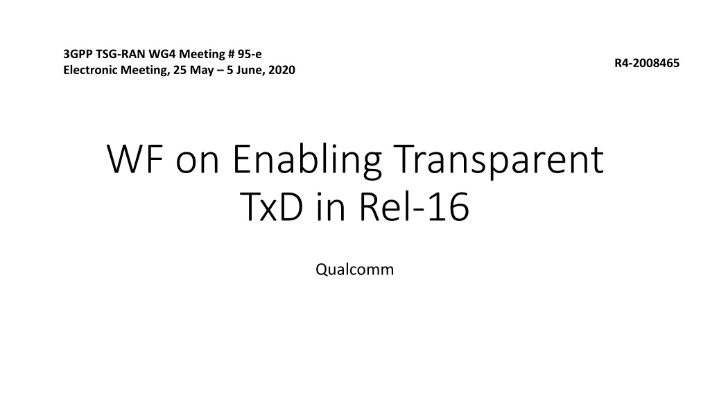
3GPP TSG-RAN WG4 Meeting # 95-e Electronic Meeting, 25 May 5 June, 2020 R4-2008465 WF on Enabling Transparent TxD in Rel-16 Qualcomm
Issue 3-3-1: Summing the power and emissions Motivation is to define requirements so that power is measured correctly for all implementations Option 1: Use requirements apply to a sum of both connectors . Option 2: Use measured as sum of each antenna connector .
Issue 3-3-2: Unwanted emissions for Transparent TxD: MPR study Possible WF: Simulation/measurement assumptions for MPR study for 2Tx UE s Follow 29 dBm WI assumptions in R4-2005190 Two 20dBm Tx chains are not precluded Two 23dBm Tx chains are not precluded Two 26dBm Tx chains are precluded MPRs are defined for each power class separately PC3 = 2x20dBm PC2 = 2x23dBm
Issue 3-3-2: Unwanted emissions for Transparent TxD: how to write emission requirements Motivation is to ensure correct requirement setting for unwanted emissions Option 1: Define requirements apply to a sum of both connectors . Issue 3-3- 1 option 1 Option 2: Define measured as the sum of the emissions from all antenna connectors . Same as issue 3-3-1 Option 2 Option 3: Measured per antenna connector against a 3 dB tighter emissions requirement per connector (for two antenna connectors).
Issue 3-3-3: ACLR for Transparent TxD ACLR is defined as follows ACLRUE = (PADJ, TX1 + PADJ, TX2) / (POWN, TX1 + POWN, TX2) Where PADJ, TX1 = power of the adjacent channel on TX port 1 POWN, TX1 = power of own channel on TX port 1 And TX2 similarly.
Issue 3-3-4: EVM for Transparent TxD Agree EVM defined as ??? = Needed changes into the TS are TBD Annex F 6.4D 2+ ?2 ???2 2)/(?1 + ?2) (?1 ???1
Issue 3-3-5: Declaration for default TX connector Motivation is to clarify what is UE behavior and TE assumptions in RX and BB tests Narrow down to one of the following in next meeting Option 1a: TE needs to detect all antenna connectors for ACK and NACK and any other expected response from UE Option 1b: TE needs to detect all declared TX antenna connectors for ACK and NACK and any other expected response from UE Option 2: UE declares which connector is primary TX connector from which ACK and NACK and any other expected response from UE is transmitted in all cases And send LS to RAN5 about RAN4 conclusion
Issue 3-3-6: UE behavior under conformance testing Motivation is to guide how to test requirements that require power changes such as relative power control Option 1a: UE will keep the tx diversity status unchanged in conformance testing. Option 1b: Test mode signalling is implemented to instruct UE to keep TX div status unchanged Option 2: TE will detect and sum for every power step and change in condition from all connector (according to the issue 3-3-5 outcome)
Issue 3-3-7: Power splitting behavior Motivation is to discuss and agree what implementations are excuded Option 1: Only allow equal power split between connectors Excludes 17+17+20 dBm implementations Excludes power control optimizations Option 2: Allow any power split between connectors Note for discussion RAN1 language mandates UE to split power equally between logical antenna ports. This allows 17+17 dBm = port 1 and 20 dBm = port 2 case What is the motivation for RAN4 to disallow this? Or power optimization for example for 24 dBm output power realization 23 + 17 dBm for maximized efficiency?

