DIGITAL FILTER DESIGN
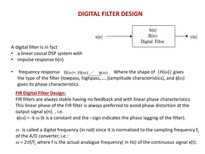
A digital filter is a linear causal DSP system with an impulse response h(n), where |H(.)| represents the frequency response determining the filter type. FIR filters are stable with linear phase characteristics. Learn how to design FIR digital filters by computing N, determining the impulse response, selecting windows, and finding the frequency response.

Download Presentation

Please find below an Image/Link to download the presentation.
The content on the website is provided AS IS for your information and personal use only. It may not be sold, licensed, or shared on other websites without obtaining consent from the author.If you encounter any issues during the download, it is possible that the publisher has removed the file from their server.
You are allowed to download the files provided on this website for personal or commercial use, subject to the condition that they are used lawfully. All files are the property of their respective owners.
The content on the website is provided AS IS for your information and personal use only. It may not be sold, licensed, or shared on other websites without obtaining consent from the author.
E N D
Presentation Transcript
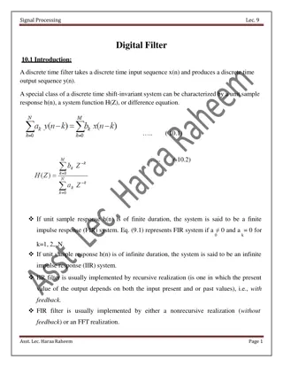
DIGITAL FILTER DESIGN A digital filter is in fact a linear causal DSP system with impulse response h(n) Where the shape of |H( )| gives frequency response the type of the filter (lowpass, highpass, ..)(amplitude characteristics), and ( ) gives its phase characteristics FIR Digital Filter Design: FIR filters are always stable having no feedback and with linear phase characteristics This linear phase of the FIR filter is always preferred to avoid phase distortion at the output signal y(n). , i.e. ( ) = -k (k is a constant and the sign indicates the phase lagging of the filter). is called a digital frequency (in rad) since it is normalized to the sampling frequency fs of the A/D converter, i.e.: = 2 f/fs where f is the actual analogue frequency( in Hz) of the continuous signal x(t).
Design procedure: we discuss how to find h(n) as symmetric around taking N as an odd number
1) Compute N: we discuss how to find N: usually, N gives filter roll of ( how fast is the transition from passband to stopband or how is the obtained response is closed to ideal response). In general: where k1 and k2 are gain values at 1 and 2 and k1 is the -3dB level and k2 is usually taken as the maximum SLL 2) Now to find the overall impulse response h(n) with windowing , then: h(n) = hd(n) w(n) where hd(n) depends on filter type (LFP,HPF,BPF,BSF..) and w(n) is usually chosen according to the required sidelobe level (SLL)at stopband
Several types of windows are used, but the most commonly used are listed below:
Ex: Design and realize a linear phase digital lowpass filter (LPF) having 3dB cutoff frequency of 7.5KHz. and stopband attenuation of at least 40dB at 35KHz. Find the difference equation and the frequency response of this filter. Use fs = 100KHz. k2= -40dB, this gives maxi SLL Hanning window is chosen since its max. SLL is -44dB, then k=4 Next, we find N: =2 f/fs If f1=7.5KHz, then 1=2 (7.5)/100=0.15 rad f2=35KHz, then 2=2 (35)/100=0.7 rad Next we find the midpoint =(N-1)/2=(15-1)/2=7 c= 1=0.15 rad ( -3dB point). n 7
hd(7)=c/=0.15. h(n)=hd(n) w(n) And h(7)=hd(7)= 0.15 since w(7)=1. Due to symmetry around n=7, only h(n) values at n=0,1,2,3,4,5,6 need to be calculated
Example: Find the impulse response of a digital linear phase bandstop filter (BSF) having: 1- 3dB cutoff at 20Hz 1400Hz. 2- stopband attenuation of at least 40dB at 660Hz and 750Hz. Use fs=3KHz. the difference equation as: y(n)=x(n) h(0)+x(n-1) h(1)+x(n-2) h(n-2)+ +x(n-14) h(14) Solution: since linear phase, then this is FIR filter. For 40dB SLL, we use Hanning window the frequency response: ( ) = -7 rad 6 = n = + | ( | ) . 0 15 2 ( ) cos( ( 7 )) H h n n 0 H.W: Repeat previous example for a HPF with 3dB cutoff at 0.7 rad and stopband attenuation of at least 50dB at 0.2 rad. N=max(N1,N2)=max(19,19)=19. This gives =9. The u and are the 3dB cutoff of the highpass and lowpass sections respectively, u=2 (1400)/3000=(14/15) rad And = 2 (20)/3000= /75 rad
for 18 n 0, n9 And hd(9)= [ -(14/15) +( /75)]/ =0.08


 Compute N: we discuss how to find N: usually, N gives")


, then")


=c/=0.15.")