Digital Design: Carry Lookahead Adder

E
E
L
4
7
1
2
D
i
g
i
t
a
l
D
e
s
i
g
n
(
C
a
r
r
y
L
o
o
k
a
h
e
a
d
A
d
d
e
r
)


V
H
D
L
D
e
s
i
g
n
S
t
y
l
e
s

Components and
interconnects
s
t
r
u
c
t
u
r
a
l
V
H
D
L
D
e
s
i
g
n
S
t
y
l
e
s

Concurrent
statements


b
e
h
a
v
i
o
r
a
l
(
s
e
q
u
e
n
t
i
a
l
)
•
R
e
g
i
s
t
e
r
s
•
S
t
a
t
e
m
a
c
h
i
n
e
s
•
I
n
s
t
r
u
c
t
i
o
n
d
e
c
o
d
e
r
s
Sequential statements


Subset most suitable for synthesis
•
T
e
s
t
b
e
n
c
h
e
s


R
e
g
i
s
t
e
r
T
r
a
n
s
f
e
r
L
e
v
e
l
(
R
T
L
)
D
e
s
i
g
n
D
e
s
c
r
i
p
t
i
o
n


R
e
g
i
s
t
e
r
s


…
T
o
d
a
y
’
s
T
o
p
i
c


M
L
U
E
x
a
m
p
l
e
M
L
U
B
l
o
c
k
D
i
a
g
r
a
m
B
A
NEG_A
NEG_B
IN0
IN1
IN2
IN3
OUTPUT
SEL1
SEL0
MUX_4_1
L0
L1
NEG_Y
Y
Y1
A1
B1
MUX_0
MUX_1
MUX_2
MUX_3
M
L
U
:
E
n
t
i
t
y
D
e
c
l
a
r
a
t
i
o
n
LIBRARY ieee;
USE ieee.std_logic_1164.all;
ENTITY mlu IS
PORT(
NEG_A : IN STD_LOGIC;
NEG_B : IN STD_LOGIC;
NEG_Y : IN STD_LOGIC;
A : IN STD_LOGIC;
B : IN STD_LOGIC;
L1 : IN STD_LOGIC;
L0 : IN STD_LOGIC;
Y : OUT STD_LOGIC
);
END mlu;
M
L
U
:
A
r
c
h
i
t
e
c
t
u
r
e
D
e
c
l
a
r
a
t
i
v
e
S
e
c
t
i
o
n
ARCHITECTURE mlu_dataflow OF mlu IS
SIGNAL A1 : STD_LOGIC;
SIGNAL B1 : STD_LOGIC;
SIGNAL Y1 : STD_LOGIC;
SIGNAL MUX_0 : STD_LOGIC;
SIGNAL MUX_1 : STD_LOGIC;
SIGNAL MUX_2 : STD_LOGIC;
SIGNAL MUX_3 : STD_LOGIC;
SIGNAL L:
STD_LOGIC_VECTOR(1 DOWNTO 0);
M
L
U
-
A
r
c
h
i
t
e
c
t
u
r
e
B
o
d
y
BEGIN
A1<=
NOT A WHEN (NEG_A='1') ELSE
A;
B1<=
NOT B WHEN (NEG_B='1') ELSE
B;
Y
<=
NOT Y1 WHEN (NEG_Y='1') ELSE
Y1;
MUX_0
<=
A1 AND B1;
MUX_1
<=
A1 OR B1;
MUX_2
<=
A1 XOR B1;
MUX_3
<=
A1 XNOR B1;
L <= L1 & L0;
with (L) select
Y1
<=
MUX_0 WHEN "00",
MUX_1 WHEN "01",
MUX_2 WHEN "10",
MUX_3 WHEN OTHERS;
END mlu_dataflow;
B
u
f
f
e
r
s
(b) Equivalent circuit
(c) Truth table
x
f
e
(a) A tri-state buffer
0
0
1
1
0
1
0
1
Z
Z
0
1
f
e
x
x
f
e
= 0
e
= 1
x
f
Tri-state Buffer
Four types of Tri-state Buffers
T
r
i
-
s
t
a
t
e
B
u
f
f
e
r
–
e
x
a
m
p
l
e
(
1
)
LIBRARY ieee;
USE ieee.std_logic_1164.all;
ENTITY tri_state IS
PORT ( ena: IN STD_LOGIC;
input: IN STD_LOGIC;
output: OUT STD_LOGIC
);
END tri_state;
T
r
i
-
s
t
a
t
e
B
u
f
f
e
r
–
e
x
a
m
p
l
e
(
2
)
ARCHITECTURE dataflow OF tri_state IS
BEGIN
output <= input WHEN (ena = ‘
1
’) ELSE ‘Z’;
END dataflow;
W
i
r
e
a
n
d
B
u
s
e
s
M
e
r
g
i
n
g
w
i
r
e
s
a
n
d
b
u
s
e
s
SIGNAL
a
: STD_LOGIC_VECTOR(3
DOWNTO
0);
SIGNAL
b
: STD_LOGIC_VECTOR(4
DOWNTO
0);
SIGNAL
c
: STD_LOGIC;
SIGNAL
d
: STD_LOGIC_VECTOR(9
DOWNTO
0);
d
<= a & b & c;
4
5
10
a
b
c
d
S
p
l
i
t
t
i
n
g
b
u
s
e
s
SIGNAL
a
: STD_LOGIC_VECTOR(3
DOWNTO
0);
SIGNAL
b
: STD_LOGIC_VECTOR(4
DOWNTO
0);
SIGNAL
c
: STD_LOGIC;
SIGNAL
d
: STD_LOGIC_VECTOR(9
DOWNTO
0);
a <= d(9 downto 6);
b <= d(5 downto 1);
c <= d(0);
4
5
10
a
b
c
d
C
a
r
r
y
L
o
o
k
a
h
e
a
d
A
d
d
e
r
s
I
n
t
r
o
d
u
c
t
i
o
n
There are many ways to implement a digital
function, but each approach may have
different tradeoffs
As a digital designer, you need to consider
these tradeoffs when meeting design
requirements
As an example, we’ll look into different adder
architectures and their tradeoffs
Read Section 5.4 for more details
R
i
p
p
l
e
C
a
r
r
y
A
d
d
e
r
A
d
v
a
n
t
a
g
e
:
A
r
e
a
I
m
p
a
c
t
The ripple carry adder’s area grows
linearly with bit width
Each additional bit adds another full
adder and its associated gates
+5 gates
+5 gates
+5 gates
+5 gates
D
i
s
a
d
v
a
n
t
a
g
e
:
D
e
l
a
y
I
m
p
a
c
t
The ripple carry adder’s delay also
grows linearly with bit width
Each full adder must wait for the
previous full adder to produce outputs
Lower performance with bit width!
C
1
@3
Δ
C
2
@5Δ
C
3
@7
Δ
C
4
@9
Δ
D
e
l
a
y
P
r
o
b
l
e
m
S
i
m
p
l
i
f
y
i
n
g
C
a
r
r
y
E
q
u
a
t
i
o
n
G
e
n
e
r
a
t
e
/
P
r
o
p
a
g
a
t
e
E
x
a
m
p
l
e
C
a
r
r
y
S
u
b
s
t
i
t
u
t
i
o
n
C
a
r
r
y
P
a
t
t
e
r
n
R
e
m
o
v
i
n
g
D
e
p
e
n
d
e
n
c
i
e
s
N
e
w
C
a
r
r
y
D
e
p
e
n
d
e
n
c
e
C
a
r
r
y
L
o
o
k
a
h
e
a
d
A
d
d
e
r
(
C
L
A
)
carry minterms
propagate/generate terms
carry term
[1]
C
o
n
s
t
a
n
t
D
e
l
a
y
The propagation delay is now constant,
even as the adder width increases!
Each of the CLA adder stages calculate its
outputs concurrently
By contrast, RC ripples carry through each
stage and has a variable delay based on width
A
r
e
a
C
o
s
t
O
t
h
e
r
T
r
a
d
e
o
f
f
s
?
We know of two adders with different
advantages as width increases
The ripple carry’s area grows linearly, but suffers
from linear growth in delay
The carry lookahead’s delay is constant, but
suffers from quadratic growth in area
Use hybrid architecture to limit both area and
delay growth?
H
y
b
r
i
d
A
p
p
r
o
a
c
h
Make a ripple carry architecture out of
multi-bit CLAs adders, or CLA blocks
E.g. 4-bit CLA adders connected in a ripple
carry fashion
The hybrid adder’s area grows linearly
Additional bits add another CLA adder and
its associated gates
Slower area growth than pure CLA, but
larger area than pure RC
A
r
e
a
I
m
p
a
c
t
D
e
l
a
y
I
m
p
a
c
t
The hybrid adder’s delay grows linearly
Each CLA adder must wait for the previous
CLA adder to produce outputs
But no longer on a bit-by-bit basis!
Lower delay growth than pure RC
A
l
t
e
r
n
a
t
i
v
e
H
i
e
r
a
r
c
h
i
c
a
l
A
p
p
r
o
a
c
h
In the hybrid approach, we use the RC
architecture on multi-bit CLA adders
Alternatively, we can also use the CLA
architecture with multi-bit CLA adders
Use CLA architecture to gain constant delay as
width increases
Must determine propagate and generate logic on
a CLA block-basis
A
n
o
t
h
e
r
L
o
o
k
a
t
C
a
r
r
y
E
q
u
a
t
i
o
n
s
H
i
e
r
a
r
c
h
i
c
a
l
C
a
r
r
y
S
u
b
s
t
i
t
u
t
i
o
n
H
i
e
r
a
r
c
h
i
c
a
l
S
u
b
s
t
i
t
u
t
i
o
n
s
R
e
m
o
v
i
n
g
D
e
p
e
n
d
e
n
c
i
e
s
H
i
e
r
a
r
c
h
i
c
a
l
C
L
A
Figure 2. A hierarchical carry-lookahead adder [1]
carry terms
(steps 3 & 4)
propagate/generate
terms (steps 1 & 2)
H
i
e
r
a
r
c
h
i
c
a
l
C
L
A
Compared to pure CLA
Smaller quadratic area growth
Block propagate/generate logic extracts common propagate/generate terms
Avoids duplicating gates for common propagate/generate terms in each carry equation
Larger constant delay due to block propagate/generate logic.
Figure 2. A hierarchical carry-lookahead adder [1]
P
r
a
c
t
i
c
a
l
L
i
m
i
t
a
t
i
o
n
s
M
u
l
t
i
-
l
e
v
e
l
H
i
e
r
a
r
c
h
i
c
a
l
A
p
p
r
o
a
c
h
e
s
Similar to the past two architectures, we
can add additional hierarchical levels for
different area/delay tradeoffs
May help with fan-in/fan-out as
width increases
Ideal number of levels dependent on width
C
o
n
c
l
u
s
i
o
n
s
Two adder architectures with different
area/delay tradeoffs
Ripple carry adder
Carry lookahead adder
Two hierarchical architectures with different
area/delay tradeoffs
Hybrid architecture
Hierarchical CLA
Questions?
R
e
f
e
r
e
n
c
e
s
1.
Stephen Brown and Zvonko Vranesic. 2004.
Fundamentals of Digital Logic with VHDL
Design with CD-ROM
(2 ed.). McGraw-Hill, Inc., New York, NY, USA.
2.
http://www.gstitt.ece.ufl.edu/courses/spring19/eel4712/index.html
3.
https://ece.gmu.edu/coursewebpages/ECE/ECE545/F10/viewgraphs/ECE545_lecture5_dat
aflow.pdf
Q
u
e
s
t
i
o
n
s
?
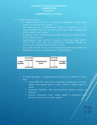
VHDL design styles, behavioral testbenches, structural components, and more in the context of digital design. Learn about Register Transfer Level (RTL) design, combinational logic, and MLU examples with architecture and body descriptions.

Download Presentation

Please find below an Image/Link to download the presentation.
The content on the website is provided AS IS for your information and personal use only. It may not be sold, licensed, or shared on other websites without obtaining consent from the author.If you encounter any issues during the download, it is possible that the publisher has removed the file from their server.
You are allowed to download the files provided on this website for personal or commercial use, subject to the condition that they are used lawfully. All files are the property of their respective owners.
The content on the website is provided AS IS for your information and personal use only. It may not be sold, licensed, or shared on other websites without obtaining consent from the author.
E N D
Presentation Transcript
EEL4712 Digital Design (Carry Lookahead Adder)
VHDL Design Styles VHDL Design Styles Testbenches behavioral (sequential) structural dataflow Components and interconnects Concurrent statements Sequential statements Registers State machines Instruction decoders Subset most suitable for synthesis
Register Transfer Level (RTL) Design Description Today s Topic Combinational Logic Combinational Logic Registers
MLU Block Diagram MUX_0 A1 0 A MUX_4_1 1 Y1 IN0 MUX_1 MUX_2 NEG_A IN1 0 Y OUTPUT IN2 1 SEL0 IN3 SEL1 NEG_Y B1 0 B L1 L0 1 MUX_3 NEG_B
MLU: Entity Declaration LIBRARY ieee; USE ieee.std_logic_1164.all; ENTITY mlu IS PORT( NEG_A : IN STD_LOGIC; NEG_B : IN STD_LOGIC; NEG_Y : IN STD_LOGIC; A : IN STD_LOGIC; B : IN STD_LOGIC; L1 : IN STD_LOGIC; L0 : IN STD_LOGIC; Y : OUT STD_LOGIC ); END mlu;
MLU: Architecture Declarative Section ARCHITECTURE mlu_dataflow OF mlu IS SIGNAL A1 : STD_LOGIC; SIGNAL B1 : STD_LOGIC; SIGNAL Y1 : STD_LOGIC; SIGNAL MUX_0 : STD_LOGIC; SIGNAL MUX_1 : STD_LOGIC; SIGNAL MUX_2 : STD_LOGIC; SIGNAL MUX_3 : STD_LOGIC; SIGNAL L: STD_LOGIC_VECTOR(1 DOWNTO 0);
MLU - Architecture Body BEGIN A1<= NOT A WHEN (NEG_A='1') ELSE A; B1<= NOT B WHEN (NEG_B='1') ELSE B; Y <= NOT Y1 WHEN (NEG_Y='1') ELSE Y1; MUX_0 <= A1 AND B1; MUX_1 <= A1 OR B1; MUX_2 <= A1 XOR B1; MUX_3 <= A1 XNOR B1; L <= L1 & L0; with (L) select Y1 <= MUX_0 WHEN "00", MUX_1 WHEN "01", MUX_2 WHEN "10", MUX_3 WHEN OTHERS; END mlu_dataflow;
Tri-state Buffer e x f e = 0 (a) A tri-state buffer x f e = 1 f e x x f 0 0 1 1 0 1 0 1 Z Z 0 1 (b) Equivalent circuit (c) Truth table
Four types of Tri-state Buffers e e f f x x (a) (b) e e f f x x (c) (d)
Tri-state Buffer example (1) LIBRARY ieee; USE ieee.std_logic_1164.all; ENTITY tri_state IS PORT ( ena: IN STD_LOGIC; input: IN STD_LOGIC; output: OUT STD_LOGIC ); END tri_state;
Tri-state Buffer example (2) ARCHITECTURE dataflow OF tri_state IS BEGIN output <= input WHEN (ena = 1 ) ELSE Z ; END dataflow;
Merging wires and buses a 4 10 d b 5 c SIGNAL a: STD_LOGIC_VECTOR(3 DOWNTO 0); SIGNAL b: STD_LOGIC_VECTOR(4 DOWNTO 0); SIGNAL c: STD_LOGIC; SIGNAL d: STD_LOGIC_VECTOR(9 DOWNTO 0); d <= a & b & c;
Splitting buses a 4 10 d b 5 c SIGNAL a: STD_LOGIC_VECTOR(3 DOWNTO 0); SIGNAL b: STD_LOGIC_VECTOR(4 DOWNTO 0); SIGNAL c: STD_LOGIC; SIGNAL d: STD_LOGIC_VECTOR(9 DOWNTO 0); a <= d(9 downto 6); b <= d(5 downto 1); c <= d(0);
Carry Lookahead Adders
Introduction There are many ways to implement a digital function, but each approach may have different tradeoffs As a digital designer, you need to consider these tradeoffs when meeting design requirements As an example, we ll look into different adder architectures and their tradeoffs Read Section 5.4 for more details
Ripple Carry Adder Y X Cin Full Adder (FA) x y cin ? = ? ? ??? ????= ?? + ????+ ???? FA cout S Cout S Ripple Carry Adder A ripple carry (RC) adder is a series of full adders connected by the carry bit Y3 X3 Y2 X2 Y1 X1 Y0 X0 C0 FA3 FA2 FA1 FA0 C3 C2 C1 C4 S3 S2 S1 S0
Advantage: Area Impact The ripple carry adder s area grows linearly with bit width Y3 X3 Y2 X2 Y1 X1 Y0 X0 C0 Area (# of gates) C3 C2 C1 FA3 FA2 FA1 FA0 C4 +5 gates S3 S2 S1 S0 +5 gates +5 gates +5 gates Width Each additional bit adds another full adder and its associated gates
Disadvantage: Delay Impact The ripple carry adder s delay also grows linearly with bit width Y3 X3 Y2 X2 Y1 X1 Y0 X0 C0 C3 C2 Delay C1 FA3 FA2 FA1 FA0 C4 S3 S2 S1 S0 C4@9 C3@7 C2@5 C1@3 Width Each full adder must wait for the previous full adder to produce outputs Lower performance with bit width!
Delay Problem Delay is dependent on the carry bit rippling through each adder ??+1= ????+ ??+ ???? Can we quickly determine the previous carry s value and reduce delay? ??= ?? 1?? 1+ ?? 1+ ?? 1?? 1
Simplifying Carry Equation Let s first simplify how we look at the carry equation Carry equation: ??+1= ????+ ??+ ???? Simplified: ??+1= ??+ ???? ??= ???? ??= ??+ ?? How is carry determined in a given adder stage? Adder generates a carry based on gi When gi = 1, ci+1 = (1) + pici = 1 Adder propagates previous carry based on pi When pi = 1, ci+1 = gi + (1)ci = gi + ci
Generate/Propagate Example Example: 0001 + 1011 Generate signals (??= ????) FA0 generates a carry (??) 1 0001 +1011 0 Propagate signals (??= ??+ ??) FA1 asserts its carry (??) by propagating FA0 s carry (??) 11 0001 +1011 00 0011 0001 +1011 1100 FA3 de-asserts its carry (??) by propagating FA2 s carry (??)
Carry Substitution Let s use substitution to see how the carry bit, ci+1, is impacted by an earlier adder stage Carry equation for adder i+1 and i: ??+1= ??+ ????, or ??= ?? 1+ ?? 1?? 1 With substitution ci ??+1= ??+ ???? 1+ ?? 1?? 1 ??+1= ??+ ???? 1+ ???? 1?? 1
Carry Pattern Carry Equation: ??+1= ??+ ???? Substitutions: ?1= ?0+ ?0?0 ?2= ?1+ ?1?1 ?2= ?1+ ?1??+ ???? ?2= ?1+ ?1?0+ ?1?0?0 ?3= ?2+ ?2?2 ?3= ?2+ ?2??+ ????+ ?????? ?3= ?2+ ?2?1+ ?2?1?0+ ?2?1?0?0 c1 c2
Removing Dependencies The carry signal (ci+1) is now determined by an earlier adder stage s carry (ci-1, ci-2). ??+1= ??+ ???? 1+ ???? 1?? 1 Case 1 Case 2 Case 3 ??+1= ??+ ???? 1+ ???? 1?? 2+ ???? 1?? 2?? 2 Case 1 Case 2 Case 3 ??+1 is dependent on the following: 1. The current stage generating a carry (??) 2. The current stage propagating a generated carry from a previous stage (???? 1) or (???? 1+ ???? 1?? 2) 3. The current and previous stages propagating a carry from an earlier stage (???? 1?? 1) or (???? 1?? 2?? 2) We can perform substitution for each carry bit
New Carry Dependence Through substitution, every carry signal can be a function of solely c0, x, and y Can determine carry when inputs are ready Avoids waiting for the carry to ripple (ci-1) ?3= ?2+ ?2?1+ ?2?1?0+ ?2?1?0?0 Three logic level delay Produce ?? and ?? terms from ?? and ?? Produce carry minterms (e.g. ?2?1, ?2?1?0, and ?2?1?0?0) Produce final carry terms (ci) from minterms
Carry Lookahead Adder (CLA) Steps Produce ?? and ?? terms from ?? and ?? Produce carry minterms (e.g. ?2?1, ?2?1?0, and ?2?1?0?0) Produce final carry terms (ci) from minterms All carry terms calculated concurrently and independent of previous carry calculation propagate/generate terms carry minterms carry term [1]
Constant Delay The propagation delay is now constant, even as the adder width increases! Each of the CLA adder stages calculate its outputs concurrently By contrast, RC ripples carry through each stage and has a variable delay based on width Delay RC CLA Width
Area Cost Area now grows quadratically with width Propagate/generate logic grows with each stage ?2= ?1+ ?1?0+ ?1?0?0 ?3= ?2+ ?2?1+ ?2?1?0+ ?2?1?0?0 ?4= ?3+ ?3?2+ ?3?2?1+ ?3?2?1?0+ ?3?2?1?0?0 Area (# of gates) RC CLA Width Not practical for larger adders
Other Tradeoffs? We know of two adders with different advantages as width increases The ripple carry s area grows linearly, but suffers from linear growth in delay The carry lookahead s delay is constant, but suffers from quadratic growth in area Use hybrid architecture to limit both area and delay growth?
Hybrid Approach Make a ripple carry architecture out of multi-bit CLAs adders, or CLA blocks E.g. 4-bit CLA adders connected in a ripple carry fashion Y15-12 X15-12 Y11-8 X11-8 Y7-4 X7-4 Y3-0 X3-0 C0 4-bit CLA3 4-bit CLA2 4-bit CLA1 4-bit CLA0 C12 C8 C4 C4 S15-12 S11-8 S7-4 S3-0
Area Impact The hybrid adder s area grows linearly Additional bits add another CLA adder and its associated gates Slower area growth than pure CLA, but larger area than pure RC Y15-12 X15-12 Y11-8 X11-8 Y7-4 X7-4 Y3-0 X3-0 C0 Area (# of gates) 4-bit CLA3 4-bit CLA2 4-bit CLA1 4-bit CLA0 C12 C8 C4 C4 S15-12 S11-8 S7-4 S3-0 Width RC CLA Hybrid
Delay Impact The hybrid adder s delay grows linearly Each CLA adder must wait for the previous CLA adder to produce outputs But no longer on a bit-by-bit basis! Lower delay growth than pure RC Delay Y15-12 X15-12 Y11-8 X11-8 Y7-4 X7-4 Y3-0 X3-0 C0 Delay 4-bit CLA3 4-bit CLA2 4-bit CLA1 4-bit CLA0 C12 C8 C4 Width C4 S15-12 S11-8 S7-4 S3-0 RC CLA Hybrid
Alternative Hierarchical Approach In the hybrid approach, we use the RC architecture on multi-bit CLA adders Alternatively, we can also use the CLA architecture with multi-bit CLA adders Use CLA architecture to gain constant delay as width increases Must determine propagate and generate logic on a CLA block-basis
Another Look at Carry Equations Let s simplify how we look at the carry eq for CLA blocks Carry equation for 4-bit CLA block: ?4= ?3+ ?3?2+ ?3?2?1+ ?3?2?1?0+ (?3?2?1?0)?0 Simplified: ?4= ?0+ ?0?0 ?0= ?3+ ?3?2+ ?3?2?1+ ?3?2?1?0 ?0= ?3?2?1?0 How is each block s carry determined? CLA block generates a carry based on Gi Last stage in CLA block generates a carry (g3) Other stages generate a carry that is propagated by later stages CLA block propagates previous carry based on Pi Each stage in CLA block propagates the input carry (p3p2p1p0)
Hierarchical Carry Substitution Let s use substitution to see how the carry bit is impacted by earlier CLA blocks Carry equation for CLA block 1 and 2: ?4= ?0+ ?0?0 ?8= ?1+ ?1?4 With substitution ?8= ?1+ ?1?0+ ?0?0 ?8= ?1+ ?1?0+ ?1?0?0 Similar to regular CLA
Hierarchical Substitutions With four 4-bit CLA blocks, ?4= ?0+ ?0?0 ?8= ?1+ ?1?4 ?8= ?1+ ?1(?0+ ?0?0) ?8= ?1+ ?1?0+ ?1?0?0 ?12= ?2+ ?2?8 ?12= ?2+ ?2?1+ ?2?1?0+ ?2?1?0?0 ?16= ?3+ ?3?12 ?16= ?3+ ?3?2+ ?3?2?1+ ?3?2?1?0+ ?3?2?1?0?0 Similar to regular CLA substitutions
Removing Dependencies The carry signal (c8) is now determined by an earlier CLA block s carry (c0). ?8= ?1+ ?1?0+ ?1?0?0 Case 1 Case 2 Case 3 ?12= ?2+ ?2?1+ ?2?1?0+ ?2?1?0?0 Case 1 Case 2 Case 3 ?4? is dependent on the following: 1. The current stage generating a carry (?1) or ?2 2. The current stage propagating a generated carry from a CLA block (?1?0) or (?2?1+ ?2?1?0) 3. The current and previous stages propagating a carry from an earlier CLA block (?1?0?0) or (?2?1?0?0) We can perform substitution for each CLA carry bit
Hierarchical CLA Steps Produce ?? and ?? terms from ?? and ?? Produce ?? and ?? terms from ?? and ?? Produce carry minterms (e.g. ?2?1, ?2?1?0, and ?2?1?0?0) Produce final carry terms (ci) from minterms propagate/generate terms (steps 1 & 2) carry terms (steps 3 & 4) Figure 2. A hierarchical carry-lookahead adder [1]
Hierarchical CLA Compared to pure CLA Smaller quadratic area growth Block propagate/generate logic extracts common propagate/generate terms Avoids duplicating gates for common propagate/generate terms in each carry equation Larger constant delay due to block propagate/generate logic. Figure 2. A hierarchical carry-lookahead adder [1]
Practical Limitations At larger bit-widths, the carry equations requires gates with many inputs Fan-in limits the number of inputs on a gate A network of smaller gates can be used to avoid fan-in at the cost of additional delay E.g. ?6?5?4?3?2?1?0?0 Ideally Practically Signals may have large fan-out as well May need to duplicate gates to limit fan-out which increases area cost
Multi-level Hierarchical Approaches Similar to the past two architectures, we can add additional hierarchical levels for different area/delay tradeoffs May help with fan-in/fan-out as width increases Ideal number of levels dependent on width
Conclusions Two adder architectures with different area/delay tradeoffs Ripple carry adder Carry lookahead adder Two hierarchical architectures with different area/delay tradeoffs Hybrid architecture Hierarchical CLA Questions?
References 1. Stephen Brown and Zvonko Vranesic. 2004. Fundamentals of Digital Logic with VHDL Design with CD-ROM (2 ed.). McGraw-Hill, Inc., New York, NY, USA. 2. http://www.gstitt.ece.ufl.edu/courses/spring19/eel4712/index.html 3. https://ece.gmu.edu/coursewebpages/ECE/ECE545/F10/viewgraphs/ECE545_lecture5_dat aflow.pdf


 Design Description")


")
")


")