DIFFRACTION AND INTERFERENCE

D
I
F
F
R
A
C
T
I
O
N
A
N
D
I
N
T
E
R
F
E
R
E
N
C
E

Specification

Superposition of waves
T
h
i
s
i
s
t
h
e
p
r
o
c
e
s
s
t
h
a
t
o
c
c
u
r
s
w
h
e
n
t
w
o
w
a
v
e
s
o
f
t
h
e
s
a
m
e
t
y
p
e
m
e
e
t
.
T
h
e
p
r
i
n
c
i
p
l
e
o
f
s
u
p
e
r
p
o
s
i
t
i
o
n
W
h
e
n
t
w
o
w
a
v
e
s
m
e
e
t
,
t
h
e
t
o
t
a
l
d
i
s
p
l
a
c
e
m
e
n
t
a
t
a
p
o
i
n
t
i
s
e
q
u
a
l
t
o
t
h
e
s
u
m
o
f
t
h
e
i
n
d
i
v
i
d
u
a
l
d
i
s
p
l
a
c
e
m
e
n
t
s
a
t
t
h
a
t
p
o
i
n
t
Stationary waves
A
s
t
a
t
i
o
n
a
r
y
w
a
v
e
c
a
n
b
e
f
o
r
m
e
d
b
y
t
h
e
s
u
p
e
r
p
o
s
i
t
i
o
n
o
f
t
w
o
p
r
o
g
r
e
s
s
i
v
e
w
a
v
e
s
o
f
t
h
e
s
a
m
e
f
r
e
q
u
e
n
c
y
t
r
a
v
e
l
l
i
n
g
i
n
o
p
p
o
s
i
t
e
d
i
r
e
c
t
i
o
n
s
.
T
h
i
s
i
s
u
s
u
a
l
l
y
a
c
h
i
e
v
e
d
b
y
s
u
p
e
r
p
o
s
i
n
g
a
r
e
f
l
e
c
t
e
d
w
a
v
e
w
i
t
h
i
t
s
i
n
c
i
d
e
n
t
w
a
v
e
.
F
o
r
m
a
t
i
o
n
o
f
a
s
t
a
t
i
o
n
a
r
y
w
a
v
e
C
o
n
s
i
d
e
r
t
w
o
w
a
v
e
s
,
A
a
n
d
B
,
e
a
c
h
o
f
a
m
p
l
i
t
u
d
e
a
,
f
r
e
q
u
e
n
c
y
f
a
n
d
p
e
r
i
o
d
T
t
r
a
v
e
l
l
i
n
g
i
n
o
p
p
o
s
i
t
e
d
i
r
e
c
t
i
o
n
s
.
(
1
)
A
t
t
i
m
e
,
t
=
0
A
m
p
l
i
t
u
d
e
=
2
a
W
a
v
e
A
R
E
S
U
L
T
A
N
T
W
A
V
E
F
O
R
M
R
E
I
N
F
O
R
C
E
M
E
N
T
N
A
N
A
N
A
N
A
N
A
N
A
N
(
2
)
O
n
e
q
u
a
r
t
e
r
o
f
a
c
y
c
l
e
l
a
t
e
r
,
a
t
t
i
m
e
,
t
=
T
/
4
b
o
t
h
w
a
v
e
s
h
a
v
e
m
o
v
e
d
b
y
a
q
u
a
r
t
e
r
o
f
a
w
a
v
e
l
e
n
g
t
h
i
n
o
p
p
o
s
i
t
e
d
i
r
e
c
t
i
o
n
s
.
W
a
v
e
A
R
E
S
U
L
T
A
N
T
W
A
V
E
F
O
R
M
C
A
N
C
E
L
L
A
T
I
O
N
A
m
p
l
i
t
u
d
e
=
0
N
A
N
A
N
A
N
A
N
A
N
A
(
3
)
A
f
t
e
r
a
n
o
t
h
e
r
q
u
a
r
t
e
r
o
f
a
c
y
c
l
e
,
a
t
t
i
m
e
,
t
=
T
/
2
b
o
t
h
w
a
v
e
s
h
a
v
e
n
o
w
m
o
v
e
d
b
y
a
h
a
l
f
o
f
a
w
a
v
e
l
e
n
g
t
h
i
n
o
p
p
o
s
i
t
e
d
i
r
e
c
t
i
o
n
s
.
W
a
v
e
B
W
a
v
e
A
A
m
p
l
i
t
u
d
e
=
2
a
R
E
S
U
L
T
A
N
T
W
A
V
E
F
O
R
M
R
E
I
N
F
O
R
C
E
M
E
N
T
N
A
N
A
N
A
N
A
N
A
N
A
N
(
4
)
O
n
e
q
u
a
r
t
e
r
o
f
a
c
y
c
l
e
l
a
t
e
r
,
a
t
t
i
m
e
,
t
=
3
T
/
4
b
o
t
h
w
a
v
e
s
w
i
l
l
u
n
d
e
r
g
o
c
a
n
c
e
l
l
a
t
i
o
n
a
g
a
i
n
.
(
5
)
O
n
e
q
u
a
r
t
e
r
o
f
a
c
y
c
l
e
l
a
t
e
r
,
a
t
t
i
m
e
,
t
=
T
t
h
e
t
w
o
w
a
v
e
s
w
i
l
l
u
n
d
e
r
g
o
s
u
p
e
r
p
o
s
i
t
i
o
n
i
n
t
h
e
s
a
m
e
w
a
y
a
s
a
t
t
i
m
e
,
t
=
0
N
A
N
A
N
A
N
A
N
A
N
(
6
)
P
l
a
c
i
n
g
a
l
l
f
o
u
r
r
e
s
u
l
t
a
n
t
w
a
v
e
f
o
r
m
s
o
n
t
o
p
o
f
e
a
c
h
o
t
h
e
r
g
i
v
e
s
:
Nodes (N) and Antinodes (A)
N
O
D
E
S
a
r
e
p
o
i
n
t
s
w
i
t
h
i
n
a
s
t
a
t
i
o
n
a
r
y
w
a
v
e
t
h
a
t
h
a
v
e
t
h
e
M
I
N
I
M
U
M
(
u
s
u
a
l
l
y
z
e
r
o
)
a
m
p
l
i
t
u
d
e
.
T
h
e
s
e
h
a
v
e
b
e
e
n
m
a
r
k
e
d
b
y
a
n
‘
N
’
i
n
t
h
e
p
r
e
v
i
o
u
s
w
a
v
e
f
o
r
m
s
.
A
N
T
I
N
O
D
E
S
a
r
e
p
o
i
n
t
s
w
i
t
h
i
n
a
s
t
a
t
i
o
n
a
r
y
w
a
v
e
t
h
a
t
h
a
v
e
t
h
e
M
A
X
I
M
U
M
a
m
p
l
i
t
u
d
e
.
T
h
e
s
e
h
a
v
e
b
e
e
n
m
a
r
k
e
d
b
y
a
n
‘
A
’
i
n
t
h
e
p
r
e
v
i
o
u
s
w
a
v
e
f
o
r
m
s
a
n
d
h
a
v
e
a
n
a
m
p
l
i
t
u
d
e
e
q
u
a
l
t
o
‘
2
a
’
Comparison of stationary and progressive waves
Diffraction
Diffraction occurs when waves spread out after
passing through a gap or round an obstacle.
Diffraction becomes
more significant when
the size of the gap or
obstacle is reduced
compared with the
wavelength of the wave.
Interference
I
n
t
e
r
f
e
r
e
n
c
e
o
c
c
u
r
s
w
h
e
n
t
w
o
w
a
v
e
s
o
f
t
h
e
s
a
m
e
t
y
p
e
(
e
.
g
.
b
o
t
h
w
a
t
e
r
,
s
o
u
n
d
,
l
i
g
h
t
,
m
i
c
r
o
w
a
v
e
s
e
t
c
.
)
o
c
c
u
p
y
t
h
e
s
a
m
e
s
p
a
c
e
.
Wave superposition results in the formation of an interference pattern
made up of regions of reinforcement and cancellation.
Coherence
F
o
r
a
n
i
n
t
e
r
f
e
r
e
n
c
e
p
a
t
t
e
r
n
t
o
b
e
o
b
s
e
r
v
a
b
l
e
t
h
e
t
w
o
o
v
e
r
l
a
p
p
i
n
g
w
a
v
e
s
m
u
s
t
b
e
c
o
h
e
r
e
n
t
.
This means they will have:
1
.
t
h
e
s
a
m
e
f
r
e
q
u
e
n
c
y
2
.
a
c
o
n
s
t
a
n
t
p
h
a
s
e
d
i
f
f
e
r
e
n
c
e
If the two waves are incoherent
the pattern will continually
change usually too quickly for
observations to be made.
Path difference
P
a
t
h
d
i
f
f
e
r
e
n
c
e
i
s
t
h
e
d
i
f
f
e
r
e
n
c
e
i
n
d
i
s
t
a
n
c
e
t
r
a
v
e
l
l
e
d
b
y
t
w
o
w
a
v
e
s
.
P
a
t
h
d
i
f
f
e
r
e
n
c
e
i
s
o
f
t
e
n
m
e
a
s
u
r
e
d
i
n
‘
w
a
v
e
l
e
n
g
t
h
s
’
r
a
t
h
e
r
t
h
a
n
m
e
t
r
e
s
.
E
x
a
m
p
l
e
:
T
w
o
w
a
v
e
s
t
r
a
v
e
l
f
r
o
m
A
t
o
B
a
l
o
n
g
d
i
f
f
e
r
e
n
t
r
o
u
t
e
s
.
I
f
t
h
e
y
b
o
t
h
h
a
v
e
a
w
a
v
e
l
e
n
g
t
h
o
f
2
m
a
n
d
t
h
e
t
w
o
r
o
u
t
e
s
d
i
f
f
e
r
i
n
l
e
n
g
t
h
b
y
8
m
t
h
e
n
t
h
e
i
r
p
a
t
h
d
i
f
f
e
r
e
n
c
e
c
a
n
b
e
s
t
a
t
e
d
a
s
‘
4
w
a
v
e
l
e
n
g
t
h
s
’
o
r
‘
4
λ
’
Double slit interference with light
This was first demonstrated by Thomas Young in 1801.
The fact that light showed interference effects
supported the theory that light was a wave-like
radiation.
Experimental details
L
i
g
h
t
s
o
u
r
c
e
:
T
h
i
s
n
e
e
d
s
t
o
b
e
m
o
n
o
c
h
r
o
m
a
t
i
c
(
o
n
e
c
o
l
o
u
r
o
r
f
r
e
q
u
e
n
c
y
)
.
This can be achieved by using a colour filter with a white light.
Alternatives include using monochromatic light sources such as a
sodium lamp or a laser.
S
i
n
g
l
e
s
l
i
t
:
Used to obtain a coherent light source. This is not needed if a laser is
used.
D
o
u
b
l
e
s
l
i
t
s
:
Typical width 0.1mm; typical separation 0.5mm.
D
o
u
b
l
e
s
l
i
t
t
o
f
r
i
n
g
e
d
i
s
t
a
n
c
e
:
With a screen typically 1.0m.
The distance can be shorter if a microscope is used to observe the
fringes.
Interference fringes
Interference fringes are formed where the two
diffracted light beams from the double slit
overlap.
A
b
r
i
g
h
t
f
r
i
n
g
e
i
s
f
o
r
m
e
d
w
h
e
r
e
t
h
e
l
i
g
h
t
f
r
o
m
o
n
e
s
l
i
t
r
e
i
n
f
o
r
c
e
s
t
h
e
l
i
g
h
t
f
r
o
m
t
h
e
o
t
h
e
r
s
l
i
t
.
A
t
a
b
r
i
g
h
t
f
r
i
n
g
e
t
h
e
l
i
g
h
t
f
r
o
m
b
o
t
h
s
l
i
t
s
w
i
l
l
b
e
i
n
p
h
a
s
e
.
They will have path differences equal to a whole
number of wavelengths: 0, 1
λ
, 2
λ
, 3
λ
etc…
A
d
a
r
k
f
r
i
n
g
e
i
s
f
o
r
m
e
d
d
u
e
t
o
c
a
n
c
e
l
a
t
i
o
n
w
h
e
r
e
t
h
e
l
i
g
h
t
f
r
o
m
t
h
e
s
l
i
t
s
i
s
1
8
0
°
o
u
t
o
f
p
h
a
s
e
.
They will have path differences of:
1
/
2
λ
,
3
/
2
λ
,
5
/
2
λ
etc..
Young’s slits equation
f
r
i
n
g
e
s
p
a
c
i
n
g
,
w
=
λ
D
/
s
where:
s
i
s
t
h
e
s
l
i
t
s
e
p
a
r
a
t
i
o
n
D
i
s
t
h
e
d
i
s
t
a
n
c
e
f
r
o
m
t
h
e
s
l
i
t
s
t
o
t
h
e
s
c
r
e
e
n
λ
i
s
t
h
e
w
a
v
e
l
e
n
g
t
h
o
f
t
h
e
l
i
g
h
t
Question 1
Calculate the fringe spacing
obtained from a double slit
experiment if the double slits are
separated by 0.50mm and the
distance from the slits to a screen
is 1.5m with (a) red light
(wavelength 650nm and (b) blue
light (wavelength 450nm).
f
r
i
n
g
e
s
p
a
c
i
n
g
w
=
λ
D
/
s
(
a
)
r
e
d
l
i
g
h
t
:
w = (650nm x 1.5m) / (0.50mm)
= (650 x 10
-9
m x 1.5m)
/ (5 x 10
-4
m)
= 0.00195m
=
2
.
0
m
m
(
b
)
b
l
u
e
l
i
g
h
t
:
w
=
1
.
4
m
m
Question 2
Calculate the wavelength of the
green light that produces 10
fringes over a distance of 1.0cm
if the double slits are separated
by 0.40mm and the distance
from the slits to the screen is
80cm
f
r
i
n
g
e
s
p
a
c
i
n
g
w
=
1
.
0
c
m
/
1
0
= 0.10 cm
f
r
i
n
g
e
s
p
a
c
i
n
g
w
=
λ
D
/
s
becomes:
λ
=
w
s
/
D
= (0.10cm x 0.40mm) / (80cm)
= (0.001m x 0.0004m) / (0.80m)
= 0.000 000 5m
w
a
v
e
l
e
n
g
t
h
=
5
0
0
n
m
Demonstrating interference with a laser
A laser
(
L
i
g
h
t
A
m
p
l
i
f
i
c
a
t
i
o
n
b
y
S
t
i
m
u
l
a
t
e
d
E
m
i
s
s
i
o
n
o
f
R
a
d
i
a
t
i
o
n
)
i
s
a
s
o
u
r
c
e
o
f
c
o
h
e
r
e
n
t
m
o
n
o
c
h
r
o
m
a
t
i
c
l
i
g
h
t
.
White light fringes
Every colour produces a
bight central fringe.
Therefore with white light
there is also a bright central
white fringe.
The other fringes do not
coincide resulting in fringes
that are tinted blue on the
inside and red on the outside.
The fringes become less
distinct away from the centre.
Diffraction from a single slit
A single slit also produces
a fringe pattern.
The central fringe is much
brighter than and twice the
width of the others.
D
o
u
b
l
e
s
l
i
t
p
a
t
t
e
r
n
w
i
t
h
s
i
n
g
l
e
s
l
i
t
d
i
f
f
r
a
c
t
i
o
n
Transmission diffraction grating
A transmission diffraction grating consists of a glass or
plastic slide with many closely spaced slits ruled onto it
(typically 500 per mm).
Note: A CD or DVD disc acts as a reflection diffraction grating
Grating and monochromatic light
When a parallel beam of
monochromatic light is
incident normally with the
grating the light is transmitted
in certain directions only.
This happens because:
•
the light is diffracted by
each slit in the grating.
•
the diffracted light from
adjacent slits reinforces only
in a few directions. In all
other directions cancellation
occurs.
The central beam is referred
as the ‘zero order beam’ and
is in the same direction as
the incident beam.
Other transmitted beams are
numbered outwards from the
zero order beam.
The pattern of beams is
symmetric about the zero
order beam.
The angle between the
beams increases if:
•
the wavelength of the
light is increased
•
the width of the slits in
the grating is decreased
(more lines per mm)
Grating and white light
Each wavelength produces its own set of lines.
The zero order beam is white.
The other beams are spectra with red showing the greatest
angles
Diffraction grating equation
d
s
i
n
θ
=
n
λ
where:
d
=
t
h
e
g
r
a
t
i
n
g
s
p
a
c
i
n
g
(
t
h
e
d
i
s
t
a
n
c
e
between the centres of adjacent slits
drawn on the grating)
n
=
t
h
e
b
e
a
m
o
r
d
e
r
n
u
m
b
e
r
(
0
,
1
,
2
e
t
c
.
.
)
λ
=
t
h
e
w
a
v
e
l
e
n
g
t
h
o
f
t
h
e
l
i
g
h
t
θ
=
t
h
e
a
n
g
l
e
b
e
t
w
e
e
n
t
h
e
b
e
a
m
i
n
question and the zero order beam
N
o
t
e
:
T
h
e
n
u
m
b
e
r
o
f
s
l
i
t
s
p
e
r
m
e
t
r
e
,
N
i
n
t
h
e
g
r
a
t
i
n
g
i
s
g
i
v
e
n
b
y
:
N
=
1
/
n
Diffraction grating equation derivation
L
e
t
θ
b
e
t
h
e
a
n
g
l
e
b
e
t
w
e
e
n
t
h
e
z
e
r
o
o
r
d
e
r
m
a
x
i
m
u
m
a
n
d
t
h
e
n
t
h
o
r
d
e
r
m
a
x
i
m
u
m
.
F
o
r
t
h
i
s
t
o
o
c
c
u
r
t
h
e
p
a
t
h
d
i
f
f
e
r
e
n
c
e
b
e
t
w
e
e
n
t
h
e
l
i
g
h
t
f
r
o
m
t
w
o
a
d
j
a
c
e
n
t
s
l
i
t
s
m
u
s
t
e
q
u
a
l
a
n
λ
.
I
n
t
h
e
d
i
a
g
r
a
m
o
p
p
o
s
i
t
e
d
i
s
t
a
n
c
e
Q
Y
m
u
s
t
e
q
u
a
l
n
λ
.
B
u
t
:
s
i
n
θ
=
Q
Y
/
Q
P
s
i
n
θ
=
n
λ
/
d
H
e
n
c
e
:
d
s
i
n
θ
=
n
λ
Question 1
Calculate the angle of the first order beam when red
light, wavelength 650nm is incident on a diffracting
grating that has 200 lines per mm.
d
s
i
n
θ
=
n
λ
b
e
c
o
m
e
s
:
s
i
n
θ
=
n
λ
/
d
w
i
t
h
g
r
a
t
i
n
g
s
p
a
c
i
n
g
,
d
=
1
/
2
0
0
m
m
=
0
.
0
0
5
m
m
s
i
n
θ
=
(
1
x
6
5
0
n
m
)
/
(
0
.
0
0
5
m
m
)
= (650 x 10
-9
m) / (5 x 10
-6
m)
s
i
n
θ
=
0
.
1
3
F
i
r
s
t
o
r
d
e
r
a
n
g
l
e
,
θ
=
7
.
5
°
Question 2
Calculate the wavelength of light the has a second
order angle of 30
°
when used with a diffracting
grating of 500 lines per mm.
d
s
i
n
θ
=
n
λ
b
e
c
o
m
e
s
:
λ
=
d
s
i
n
θ
/
n
w
i
t
h
g
r
a
t
i
n
g
s
p
a
c
i
n
g
,
d
=
1
/
5
0
0
m
m
=
0
.
0
0
2
m
m
λ
=
(
0
.
0
0
2
m
m
x
s
i
n
3
0
°
)
/
(
2
)
= (2 x 10
-6
m x 0.5) / (2)
w
a
v
e
l
e
n
g
t
h
=
5
x
1
0
-
7
m
=
5
0
0
n
m
Question 3
How many beams are formed when blue light, wavelength
450nm is used with a diffracting grating of 400 lines per mm.
d
s
i
n
θ
=
n
λ
b
e
c
o
m
e
s
:
n
=
d
s
i
n
θ
/
λ
g
r
a
t
i
n
g
s
p
a
c
i
n
g
,
d
=
1
/
4
0
0
m
m
=
0
.
0
0
2
5
m
m
s
i
n
θ
c
a
n
n
o
t
b
e
g
r
e
a
t
e
r
t
h
a
n
1
.
0
(
w
i
t
h
θ
=
9
0
°
)
n
=
(
0
.
0
0
2
5
m
m
x
1
.
0
)
/
(
4
5
0
n
m
)
= (2.5 x 10
-6
m) / (4.5 x 10
-7
m)
= 5.6
b
u
t
n
m
u
s
t
b
e
a
n
i
n
t
e
g
e
r
a
n
d
s
o
m
a
x
n
=
5
T
h
e
r
e
w
i
l
l
t
h
e
r
e
f
o
r
e
b
e
1
1
b
e
a
m
s
Answers:
Complete:
500
500
11.5
500
23.6
5.00
9.21
2.50
53.1
Answers:
250
Answers:
Complete:
Answers:
Answers:
Complete:
500
500
11.5
500
23.6
5.00
9.21
2.50
53.1
Answers:
250
Applications of diffraction gratings
A
d
i
f
f
r
a
c
t
i
o
n
g
r
a
t
i
n
g
c
a
n
b
e
u
s
e
d
i
n
a
s
p
e
c
t
r
o
m
e
t
e
r
t
o
s
t
u
d
y
t
h
e
s
p
e
c
t
r
u
m
o
f
l
i
g
h
t
f
r
o
m
a
n
y
l
i
g
h
t
s
o
u
r
c
e
a
n
d
t
o
m
e
a
s
u
r
e
w
a
v
e
l
e
n
g
t
h
s
v
e
r
y
a
c
c
u
r
a
t
e
l
y
.
For example the line
spectrum given off by a gas
can be used to identify its
components.
Delve into the phenomena of wave interference, diffraction, and the formation of stationary waves. Discover the principles of superposition and the creation of interference fringes using laser sources. Unveil the intriguing concept of path difference and coherence, along with the applications in spectral analysis. Explore the intricate patterns formed by the superposition of waves and the generation of stationary waves through the combination of progressive waves. Dive into the world of waves and their fascinating behaviors as they interact and create mesmerizing patterns.

Download Presentation

Please find below an Image/Link to download the presentation.
The content on the website is provided AS IS for your information and personal use only. It may not be sold, licensed, or shared on other websites without obtaining consent from the author.If you encounter any issues during the download, it is possible that the publisher has removed the file from their server.
You are allowed to download the files provided on this website for personal or commercial use, subject to the condition that they are used lawfully. All files are the property of their respective owners.
The content on the website is provided AS IS for your information and personal use only. It may not be sold, licensed, or shared on other websites without obtaining consent from the author.
E N D
Presentation Transcript
Specification Topics Interference The concept of path difference and coherence The laser as a source of coherent monochromatic light used to demonstrate interference and diffraction; comparison with non-laser light; awareness of safety issues Candidates will not be required to describe how a laser works. Requirements of two source and single source double-slit systems for the production of fringes. The appearance of the interference fringes produced by a double slit system, fringe spacing w = D / s where s is the slit separation. Diffraction Appearance of the diffraction pattern from a single slit. The plane transmission diffraction grating at normal incidence; optical details of the spectrometer will not be required. Derivation of d sin = n , where n is the order number. Applications; e.g. to spectral analysis of light from stars.
Superposition of waves This is the process that occurs when two waves of the same type meet. The principle of superposition When two waves meet, the total displacement at a point is equal to the sum of the individual displacements at that point reinforceme nt cancellation
Stationary waves A stationary wave can be formed by the superposition of two progressive waves of the same frequency travelling in opposite directions. This is usually achieved by superposing a reflected wave with its incident wave.
Formation of a stationary wave Consider two waves, A and B, each of amplitude a, frequency f and period T travelling in opposite directions. (1) At time, t = 0 RESULTANT WAVEFORM REINFORCEMENT Wave A N A N A N A N A N A N A N Wave B Amplitude = 2a
(2) One quarter of a cycle later, at time, t = T/4 both waves have moved by a quarter of a wavelength in opposite directions. Wave A RESULTANT WAVEFORM CANCELLATION N A N A N A N A N A N A Amplitude = 0 Wave B
(3) After another quarter of a cycle, at time, t = T/2 both waves have now moved by a half of a wavelength in opposite directions. RESULTANT WAVEFORM REINFORCEMENT Wave A N A N A N A N A N A N A N Wave B Amplitude = 2a
(4) One quarter of a cycle later, at time, t = 3T/4 both waves will undergo cancellation again. (6) Placing all four resultant waveforms on top of each other gives: (5) One quarter of a cycle later, at time, t = T the two waves will undergo superposition in the same way as at time, t = 0 N A N A N A N A N A N
Nodes (N) and Antinodes (A) NODES are points within a stationary wave that have the MINIMUM (usually zero) amplitude. These have been marked by an N in the previous waveforms. ANTINODES are points within a stationary wave that have the MAXIMUM amplitude. These have been marked by an A in the previous waveforms and have an amplitude equal to 2a
Comparison of stationary and progressive waves Property Stationary Wave Progressive Wave Both move with speed: c = f x Is the same for all particles within a wave All particles oscillate at the same frequency Energy & Momentum Amplitude No net transfer from one point to another Varies from zero at NODES to a maximum at ANTINODES All particles oscillate at the same frequency except those at nodes This is equal to TWICE the distance between adjacent nodes Between nodes all particles are at the same phase. Any other two particles have phase difference equal to m where m is the number of nodes between the particles Frequency Wavelength This is equal to the distance between particles at the same phase Any two particles have phase difference equal to 2 d / where d is the distance between the two particles Phase difference between two particles
Diffraction Diffraction occurs when waves spread out after passing through a gap or round an obstacle. Sea wave diffraction
Diffraction becomes more significant when the size of the gap or obstacle is reduced compared with the wavelength of the wave.
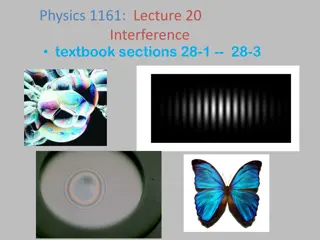
Interference Interference occurs when two waves of the same type (e.g. both water, sound, light, microwaves etc.) occupy the same space. Wave superposition results in the formation of an interference pattern made up of regions of reinforcement and cancellation.
Coherence For an interference pattern to be observable the two overlapping waves must be coherent. This means they will have: 1. the same frequency 2. a constant phase difference If the two waves are incoherent the pattern will continually change usually too quickly for observations to be made. Two coherent waves can be produced from a single wave by the use of a double slit.
Path difference Path difference is the difference in distance travelled by two waves. Path difference is often measured in wavelengths rather than metres. Example: Two waves travel from A to B along different routes. If they both have a wavelength of 2m and the two routes differ in length by 8m then their path difference can be stated as 4 wavelengths or 4
Double slit interference with light This was first demonstrated by Thomas Young in 1801. The fact that light showed interference effects supported the theory that light was a wave-like radiation. Thomas Young 1773 - 1829
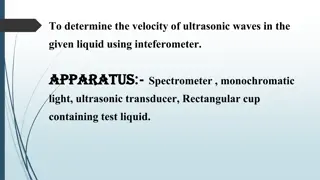
Experimental details Light source: This needs to be monochromatic (one colour or frequency). This can be achieved by using a colour filter with a white light. Alternatives include using monochromatic light sources such as a sodium lamp or a laser. Single slit: Used to obtain a coherent light source. This is not needed if a laser is used. Double slits: Typical width 0.1mm; typical separation 0.5mm. Double slit to fringe distance: With a screen typically 1.0m. The distance can be shorter if a microscope is used to observe the fringes.
Interference fringes Interference fringes are formed where the two diffracted light beams from the double slit overlap. A bright fringe is formed where the light from one slit reinforces the light from the other slit. At a bright fringe the light from both slits will be in phase. They will have path differences equal to a whole number of wavelengths: 0, 1 , 2 , 3 etc A dark fringe is formed due to cancelation where the light from the slits is 180 out of phase. They will have path differences of: 1/2 , 3/2 , 5/2 etc..
Youngs slits equation fringe spacing, w = D / s w where: s is the slit separation D is the distance from the slits to the screen is the wavelength of the light
Question 1 Calculate the fringe spacing obtained from a double slit experiment if the double slits are separated by 0.50mm and the distance from the slits to a screen is 1.5m with (a) red light (wavelength 650nm and (b) blue light (wavelength 450nm). fringe spacing w = D / s (a) red light: w = (650nm x 1.5m) / (0.50mm) = (650 x 10-9m x 1.5m) / (5 x 10⁻⁴m) = 0.00195m = 2.0mm (b) blue light: w = 1.4mm
Question 2 Calculate the wavelength of the green light that produces 10 fringes over a distance of 1.0cm if the double slits are separated by 0.40mm and the distance from the slits to the screen is 80cm fringe spacing w= 1.0cm / 10 = 0.10 cm fringe spacing w = D / s becomes: = ws / D = (0.10cm x 0.40mm) / (80cm) = (0.001m x 0.0004m) / (0.80m) = 0.000 000 5m wavelength = 500nm 1.0 cm
Demonstrating interference with a laser A laser (Light Amplification by Stimulated Emission of Radiation) is a source of coherentmonochromatic light. 0.5m to 2m
White light fringes Every colour produces a bight central fringe. Therefore with white light there is also a bright central white fringe. The other fringes do not coincide resulting in fringes that are tinted blue on the inside and red on the outside. The fringes become less distinct away from the centre. central bright fringe
Diffraction from a single slit A single slit also produces a fringe pattern. The central fringe is much brighter than and twice the width of the others. Diffraction fringe pattern produced by a red light laser
Double slit pattern with single slit diffraction 350px-Single_slit_and_double_slit2
Transmission diffraction grating A transmission diffraction grating consists of a glass or plastic slide with many closely spaced slits ruled onto it (typically 500 per mm). 500 lines per mm (magnified view) 100 lines per mm (magnified view) Note: A CD or DVD disc acts as a reflection diffraction grating
Grating and monochromatic light When a parallel beam of monochromatic light is incident normally with the grating the light is transmitted in certain directions only. This happens because: the light is diffracted by each slit in the grating. the diffracted light from adjacent slits reinforces only in a few directions. In all other directions cancellation occurs.
The central beam is referred as the zero order beam and is in the same direction as the incident beam. Other transmitted beams are numbered outwards from the zero order beam. The pattern of beams is symmetric about the zero order beam.
The angle between the beams increases if: the wavelength of the light is increased the width of the slits in the grating is decreased (more lines per mm)
Grating and white light Each wavelength produces its own set of lines. The zero order beam is white. The other beams are spectra with red showing the greatest angles
Diffraction grating equation d sin = n where: d = the grating spacing (the distance between the centres of adjacent slits drawn on the grating) n = the beam order number (0, 1, 2 etc..) = the wavelength of the light = the angle between the beam in question and the zero order beam d Note: The number of slits per metre, N in the grating is given by: N = 1 / n
Diffraction grating equation derivation Let be the angle between the zero order maximum and the nth order maximum. Q For this to occur the path difference between the light from two adjacent slits must equal a n . Y d In the diagram opposite distance QY must equal n . P But: sin = QY / QP sin = n / d Hence: d sin = n
Question 1 Calculate the angle of the first order beam when red light, wavelength 650nm is incident on a diffracting grating that has 200 lines per mm. d sin = n becomes: sin = n / d with grating spacing, d = 1/200 mm = 0.005 mm sin = (1 x 650 nm) / (0.005 mm) = (650 x 10-9 m) / (5 x 10⁻⁶ m) sin = 0.13 First order angle, = 7.5
Question 2 Calculate the wavelength of light the has a second order angle of 30 when used with a diffracting grating of 500 lines per mm. d sin = n becomes: = d sin / n with grating spacing, d = 1/500 mm = 0.002 mm = (0.002 mm x sin 30 ) / (2) = (2 x 10-6 m x 0.5) / (2) wavelength = 5 x 10⁻⁷ m = 500 nm
Question 3 How many beams are formed when blue light, wavelength 450nm is used with a diffracting grating of 400 lines per mm. d sin = n becomes: n = d sin / grating spacing, d = 1/400 mm = 0.0025 mm sin cannot be greater than 1.0 (with = 90 ) n = (0.0025 mm x 1.0) / (450 nm) = (2.5 x 10⁻⁶ m) / (4.5 x 10⁻⁷ m) = 5.6 but n must be an integer and so max n = 5 There will therefore be 11 beams
Answers: Complete: Answers: / nm N / mm-1 / d / m n 11.5 2.00 1 400 500 23.6 500 2.00 2 400 53.1 500 2.00 4 400 9.21 5.00 200 2 400 2.50 250 400 30 5
Answers: Complete: Answers: / nm N / mm-1 / d / m n 2.00 1 400 2.00 2 400 2.00 4 400 200 2 400 400 30 5
Answers: Complete: Answers: / nm N / mm-1 / d / m n 11.5 2.00 1 400 500 23.6 500 2.00 2 400 53.1 500 2.00 4 400 9.21 5.00 200 2 400 2.50 250 400 30 5
Applications of diffraction gratings A diffraction grating can be used in a spectrometer to study the spectrum of light from any light source and to measure wavelengths very accurately. diffraction grating For example the line spectrum given off by a gas can be used to identify its components. Spectrometer A line spectrum


 One quarter of a cycle later, at time, t = T/4")
 After another quarter of a cycle, at time,")
 One quarter of a")
 and Antinodes (A)")