Radio Frequency Spectrum Requirements for Civil Aviation Workshop Proceedings
This document discusses frequency assignment planning and interference models for VHF communication systems in civil aviation. It covers methodologies for establishing separation distances to prevent air-to-air interference and provides insights into interference models for co-frequency separation between aeronautical broadcast stations. The workshops in Egypt and Thailand, as well as the content related to interference caused by radio horizons, are also highlighted.
Download Presentation

Please find below an Image/Link to download the presentation.
The content on the website is provided AS IS for your information and personal use only. It may not be sold, licensed, or shared on other websites without obtaining consent from the author.If you encounter any issues during the download, it is possible that the publisher has removed the file from their server.
You are allowed to download the files provided on this website for personal or commercial use, subject to the condition that they are used lawfully. All files are the property of their respective owners.
The content on the website is provided AS IS for your information and personal use only. It may not be sold, licensed, or shared on other websites without obtaining consent from the author.
E N D
Presentation Transcript
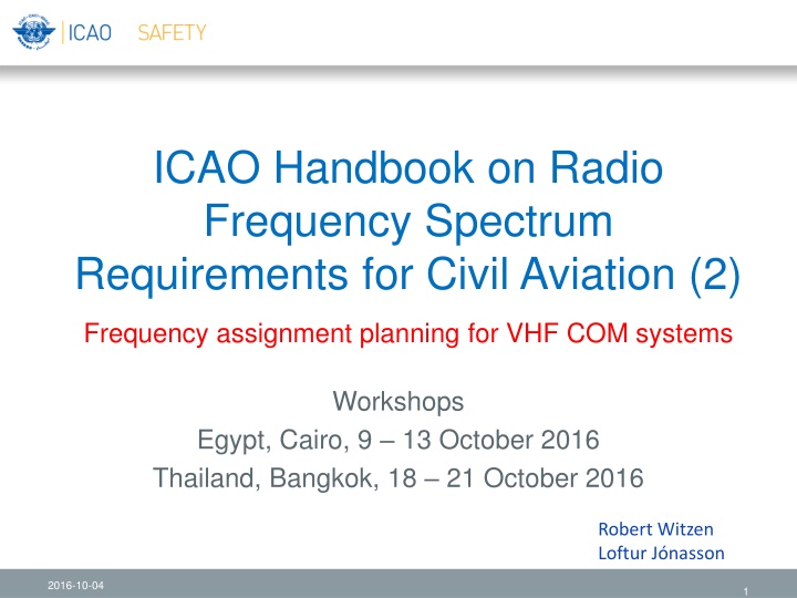
ICAO Handbook on Radio Frequency Spectrum Requirements for Civil Aviation (2) Frequency assignment planning for VHF COM systems Workshops Egypt, Cairo, 9 13 October 2016 Thailand, Bangkok, 18 21 October 2016 Robert Witzen Loftur J nasson 2016-10-04 1
Vol. II Vol. II Ch2 Interference model (co-frequency separation (1)) Ch2 VHF COM systems VHF COM systems Conforms to the general methodology in Chapter 1 Model for establishing separation distances to prevent air-to-air interference: receiver input RPd antenna input Pd e.i.r.p D b a Feeder loss Antenna gain Propagation loss Antenna gain Feeder loss Transmitter Receiver B A du PTd Fd Gd Ld Gr Fr PTr antenna input Pu receiver input RPu dd Feeder loss Antenna gain Propagation loss Transmitter Station A Range = RA = dd Station B Range = RB PTu Fu Gu Lu e.i.r.p U Minimum separation between stations A and B: Range A + Radio horizon A + Radio Horizon B +Range B 2016-10-04 2
Vol. II Vol. II Ch2 Interference model (co-frequency separation (2)) a Ch2 VHF COM systems VHF COM systems b receiver input RPd antenna input Pd e.i.r.p D B Feeder loss Antenna gain Propagation loss Antenna gain Feeder loss A Transmitter Receiver du PTd Fd Gd Ld Gr Fr PTr dd antenna input Pu receiver input RPu Station A Range = RA = dd Station B Range = RB Feeder loss Antenna gain Propagation loss Transmitter PTu Fu Gu Lu e.i.r.p U Minimum separation between stations A and B: Range A + Radio horizon A + Radio Horizon B +Range B ? ?= ?? ?? = ??.? + ?????? + ??????? ??.? + ?????? + ??????? = ??????? ???????= ??????? ?? ? ?= ??????? If du = 2*dd then ? ? = 20 log 2 = 6dB ?? 2016-10-04 3
Vol. II Vol. II Frequency assignment planning Frequency assignment planning Interference model (co-frequency separation (3)) Effect of the radio horizon (att. beyond Rh = 0.5 * DLOS) b DBLOS a B RHA RHB A Radio horizon Ground station A Range = RA Ground station B Range = RB Distance beyond line-of-sight = dBLOS 2016-10-04 4
Vol. II Vol. II Frequency assignment planning Frequency assignment planning Interference model (co-frequency separation (1)) Between Aeronautical broadcast stations (ATIS, VOLMET) Do not involve aircraft transmission Separation distances are less compared to both stations providing air-ground communications b a Broadcast station B A 15 NM RHA RA Broadcast station A 2016-10-04 5
Vol. II Vol. II Frequency assignment planning Frequency assignment planning Interference model (adj-frequency separation (1)) EUR-FMG has agreed to a revision of adjacent frequency separation criteria Desired and undesired station use 25 kHz channel spacing: 1st adjacent channel no geographical separation required Ground transmitting and receiving stations to be separated by 10 NM Special criteria apply in areas where both 8.33 kHz and 25 kHz channel spacing is used. Implemented in Frequency Finder Amendment to Handbook in progress 2016-10-04 6
Vol. II Vol. II Frequency assignment planning Frequency assignment planning Interference model (adj. frequency separation (2)) Mixed channel spacing Station 1 25 kHz channel spacing Station 2 8.33 kHz channel spacing 118.000 MHz 118.000 MHz (channel 118.005) Co-frequency 1st adj. frequency (= co-frequency at 25 kHz) 118.000 MHz 118.0833 MHz (channel 118.010) 2nd 4th adj. frequency 10 NM between DOC 118.000 MHz 118.0167, 118.025, 118.0333 MHz (channels 118.015 118.035) 5th adj. frequency No separation required 118.000 MHz 118.0417 MHz (channel 118.040) 2016-10-04 7
Frequency assignment planning for VHF air/ground communication systems (1) b a B A RHA RHB Radio horizon Ground station A Range = RA Ground station B Range = RB Separation distance between air ground communication services RA + RHA + RHB + RB Example: A =TWR (25NM, 4000ft) and B= APP-U (150 NM, 45000 ft) Min. Sep distance = 25+78+150+261=514 NM (between the stations) 2016-10-04 8
Frequency assignment planning for VHF air/ground communication systems (2) Service VICTIM TWR 25/400 AFIS 25/4000 AS Surface APP-U 150/450 APP-I 75/250 APP-L 50/120 ACC-U A/450 ACC/L A/250 FIS-U A/450 FIS/L A/250 VOLMET 260/450 ATIS 200/450 Interfer TWR 156 156 --- 338 273 212 338 273 338 273 338 338 Example of separation distances required between a TWR Service and other ATC Services Separation distances are between the edges of the relevant Designated Operational Coverage (DOC) 2016-10-04 9
Frequency assignment planning for VHF air/ground communication systems (3) b a Broadcast station B A 15 NM RHA RA Broadcast station A Separation distance between two stations providing aeronautical broadcast services; max range is 200 NM (Max) RA + RHA + 15 or RB + RHB + 15 Example: A =ATIS (200NM, 45000ft) and B= VOLMET(200 NM, 45000 ft) Min. Sep distance = 200+261+15=476 NM (between the stations) or 75 NM between the DOC of the stations 2016-10-04 10
Frequency assignment planning for VHF air/ground communication systems (4) b a B A RHA RHB Broadcast station B Radio horizon Air/ground station A Separation distance between two stations where one station is for air-ground communication and the other is providing aeronautical broadcast services Separation distances are the same as for two stations providing air-ground communications 2016-10-04 11
Frequency assignment planning for VHF air/ground communication systems (5) VICTIM TWR 25/4000 AFIS 25/4000 AS APP-U 150/450 APP- I 75/250 APP-L 50/120 ACC-U Area/450 ACC-L Area/250 FIS-U Area/450 FIS- L Area/250 VOLMET 260/450 ATIS 200/450 Service Surface 156 156 338 273 212 338 273 338 273 338 338 TWR 156 156 338 273 212 338 273 338 273 338 338 AFIS AS (Note 2) 25 338 338 520 455 394 520 455 520 455 520 520 APP-U APP-I 273 273 455 390 329 325 390 455 390 455 455 APP-L INTERFER 212 212 394 329 268 394 329 394 329 394 394 ACC-U (Note 1) 338 338 520 455 394 520 455 520 455 520 520 ACC-L (Note 1) 273 273 455 390 329 455 390 455 390 455 455 FIS-U (Note 1) 338 338 520 455 394 520 455 520 455 520 520 FIS-L (Note 1) 273 273 455 390 329 455 390 455 390 455 455 VOLMET 338 338 520 455 394 520 455 520 455 15 15 ATIS 338 338 520 455 394 520 455 520 455 15 15 2016-10-04 12
Frequency assignment planning for VHF air/ground communication systems (5) Frequency planning criteria for VDL were considered by the ACP between 2002 2008 Same methodology as for developing planning criteria for VHF voice systems Criteria for VDL (Mode 2 and Mode 4): The Handbook contains specific considerations to be taken into account when using VDL on the surface of an airport. 2016-10-04 13
