Determination of PDH Modulation Frequency
Determination of
PDH
Modulation Frequency
Daisuke TATSUMI
National astronomical observatory of Japan
#-----------------------------------------------------------------------
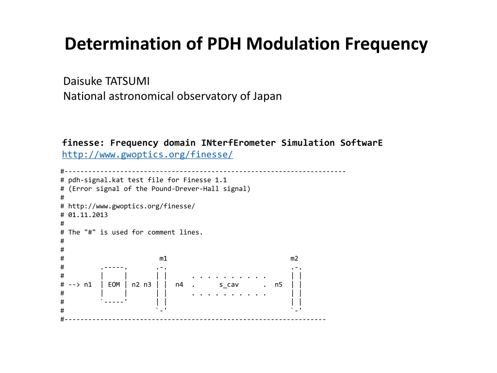
# pdh-signal.kat test file for Finesse 1.1
# (Error signal of the Pound-Drever-Hall signal)
#
# http://www.gwoptics.org/finesse/
# 01.11.2013
#
# The "#" is used for comment lines.
#
#
# m1 m2
# .-----. .-. .-.
# | | | | . . . . . . . . . . | |
# --> n1 | EOM | n2 n3 | | n4 . s_cav . n5 | |
# | | | | . . . . . . . . . . | |
# `-----' | | | |
# `-' `-'
#------------------------------------------------------------------
finesse: Frequency domain INterfErometer Simulation SoftwarE
http://www.gwoptics.org/finesse/
l i1 1 0 n0 # laser P=1W f_offset=0Hz
s s0 1 n0 n1
mod eo1 30M 0.1 3 pm n1 n2 # phase modulator f_mod=
15M
Hz
# midx=0.1 order=1
s s1 1 n2 n3
# a Fabry-Perot cavity
m m1 0.92 0.08 0 n3 n4 # mirror R=0.92 T=0.0
8
phi=0
s s_cav 0.037474 n4 n5 # space L=
37.474
mm
m m2 0.9995 0.0005 0 n5 dump # mirror R=0.
9995
T=0.
0005
phi=0
pd1 inphase 30M 0 n3 # photo diode + mixer
# f_demod=15MHz phase=0
pd1 quadrature 30M 90 n3 # photo diode + mixer
# f_demod=15MHz phase=90degrees
xaxis m2 phi lin -90 90 400 # xaxis: tune mirror m2
# from -90 to 90 (400 steps)
yaxis abs # plot `as is'
FSR (Free Spectral Range)
FSR = c /2L
c: light speed
L: cavity length
FSR = 4GHz
--> L = c /2 /FSR = 37.474 mm
FWHM of the cavity
FWHM = FSR / finesse = 4 GHz / 75 =
53.4 MHz
> ./finesse SHG.param
[INPUT]
Length= 3.747400e-02
R1= 9.200000e-01
L1 = 0.000000e+00
R2 = 9.995000e-01
L2 = 0.000000e+00
[OUTPUT]
Finesse = 74.8998
FSR = 4.000006e+09
FSR/Finesse = 5.340477e+07
Gain = 4.742051e+01
Reflectivity = 0.97629
Transmissivity = 2.371025e-02
> ./finesse SHG.param
[INPUT]
Length= 3.747400e-02
R1= 9.200000e-01
L1 = 1.000000e-04
R2 = 9.995000e-01
L2 = 1.000000e-04
[OUTPUT]
Finesse = 74.8998
FSR = 4.000006e+09
FSR/Finesse = 5.340477e+07
Gain = 4.736123e+01
Reflectivity = 0.97629
Transmissivity =
1.894449e-02
PDH signal get lower than that of optimal.
< FWHM = 60 MHz
This article by Daisuke TATSUMI from the National Astronomical Observatory of Japan discusses the determination of PDH modulation frequencies in the context of frequency domain interferometer simulation. The content focuses on the intricacies of selecting the appropriate modulation frequency for accurate simulation results. It delves into the significance of this parameter and its impact on the overall simulation process. The author's insights shed light on the importance of understanding and implementing modulation frequencies effectively in this simulation software.

Download Presentation

Please find below an Image/Link to download the presentation.
The content on the website is provided AS IS for your information and personal use only. It may not be sold, licensed, or shared on other websites without obtaining consent from the author.If you encounter any issues during the download, it is possible that the publisher has removed the file from their server.
You are allowed to download the files provided on this website for personal or commercial use, subject to the condition that they are used lawfully. All files are the property of their respective owners.
The content on the website is provided AS IS for your information and personal use only. It may not be sold, licensed, or shared on other websites without obtaining consent from the author.
E N D
Presentation Transcript
Determination of PDH Modulation Frequency Daisuke TATSUMI National astronomical observatory of Japan finesse: Frequency domain INterfErometer Simulation SoftwarE http://www.gwoptics.org/finesse/ #----------------------------------------------------------------------- # pdh-signal.kat test file for Finesse 1.1 # (Error signal of the Pound-Drever-Hall signal) # # http://www.gwoptics.org/finesse/ # 01.11.2013 # # The "#" is used for comment lines. # # # m1 m2 # .-----. .-. .-. # | | | | . . . . . . . . . . | | # --> n1 | EOM | n2 n3 | | n4 . s_cav # | | | | . . . . . . . . . . | | # `-----' | | | | # `-' `-' #------------------------------------------------------------------ . n5 | |
l i1 1 0 n0 # laser P=1W f_offset=0Hz s s0 1 n0 n1 mod eo1 30M 0.1 3 pm n1 n2 # phase modulator f_mod=15MHz # midx=0.1 order=1 s s1 1 n2 n3 # a Fabry-Perot cavity m m1 0.92 0.08 0 n3 n4 # mirror R=0.92 T=0.08 phi=0 s s_cav 0.037474 n4 n5 # space L=37.474mm m m2 0.9995 0.0005 0 n5 dump # mirror R=0.9995 T=0.0005 phi=0 pd1 inphase 30M 0 n3 # photo diode + mixer # f_demod=15MHz phase=0 pd1 quadrature 30M 90 n3 # photo diode + mixer # f_demod=15MHz phase=90degrees xaxis m2 phi lin -90 90 400 # xaxis: tune mirror m2 # from -90 to 90 (400 steps) yaxis abs # plot `as is'
FSR (Free Spectral Range) FSR = c /2L c: light speed L: cavity length FSR = 4GHz --> L = c /2 /FSR = 37.474 mm Finesse ? ?1?2 1 ?1?2 ? ~ r1= sqrt(R1) = sqrt(0.92) = 0.95917 r2= sqrt(R2) = sqrt(0.9995) = 0.99975 Finesse = 74.8998 FWHM of the cavity FWHM = FSR / finesse = 4 GHz / 75 = 53.4 MHz
> ./finesse SHG.param [INPUT] Length= 3.747400e-02 R1= 9.200000e-01 L1 = 0.000000e+00 R2 = 9.995000e-01 L2 = 0.000000e+00 [OUTPUT] Finesse = 74.8998 FSR = 4.000006e+09 FSR/Finesse = 5.340477e+07 Gain = 4.742051e+01 Reflectivity = 0.97629 Transmissivity = 2.371025e-02 > ./finesse SHG.param [INPUT] Length= 3.747400e-02 R1= 9.200000e-01 L1 = 1.000000e-04 R2 = 9.995000e-01 L2 = 1.000000e-04 [OUTPUT] Finesse = 74.8998 FSR = 4.000006e+09 FSR/Finesse = 5.340477e+07 Gain = 4.736123e+01 Reflectivity = 0.97629 Transmissivity = 1.894449e-02
< FWHM = 60 MHz PDH signal get lower than that of optimal.


")