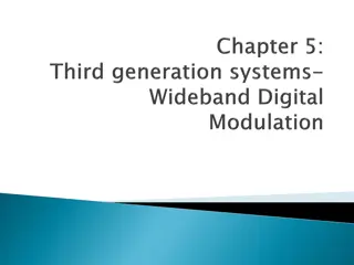
9. Multi Carrier Modulation and OFDM

9. Multi Carrier Modulation and OFDM
T
r
a
n
s
m
i
s
s
i
o
n
o
f
D
a
t
a
T
h
r
o
u
g
h
F
r
e
q
u
e
n
c
y
S
e
l
e
c
t
i
v
e
T
i
m
e
V
a
r
y
i
n
g
C
h
a
n
n
e
l
s
We have seen a wireless channel is characterized by
time
spread
and
frequency spread.
•
if
symbol duration
>>
time spread
then there is almost no Inter
Symbol Interference (ISI).
1
0
time
channel
1
0
phase still recognizable
Problem with this:
Low Data Rate!!!
S
i
n
g
l
e
C
a
r
r
i
e
r
M
o
d
u
l
a
t
i
o
n
i
n
F
l
a
t
F
a
d
i
n
g
C
h
a
n
n
e
l
s
•
this corresponds to
Flat Fading
Frequency
Frequency
channel
Flat Freq. Response
Frequency
…
i
n
t
h
e
F
r
e
q
u
e
n
c
y
D
o
m
a
i
n
•
if
symbol duration
~
time spread
then there is considerable Inter
Symbol Interference (ISI).
1
0
time
channel
?
?
phase not recognizable
S
i
n
g
l
e
C
a
r
r
i
e
r
M
o
d
u
l
a
t
i
o
n
i
n
F
r
e
q
u
e
n
c
y
S
e
l
e
c
t
i
v
e
C
h
a
n
n
e
l
s
O
n
e
S
o
l
u
t
i
o
n
:
w
e
n
e
e
d
e
q
u
a
l
i
z
a
t
i
o
n
channel
equalizer
1
0
time
1
0
time
Channel and
Equalizer
Problems with equalization:
•
it might require training data (thus loss of bandwidth)
•
if blind, it can be expensive in terms computational effort
•
always a problem when the channel is time varying
•
let
symbol duration
>>
time spread
so there is almost no Inter
Symbol Interference (ISI);
•
s
e
n
d
a
b
l
o
c
k
o
f
d
a
t
a
u
s
i
n
g
a
n
u
m
b
e
r
o
f
c
a
r
r
i
e
r
s
(
M
u
l
t
i
C
a
r
r
i
e
r
)
T
h
e
M
u
l
t
i
C
a
r
r
i
e
r
A
p
p
r
o
a
c
h
C
o
m
p
a
r
e
S
i
n
g
l
e
C
a
r
r
i
e
r
a
n
d
M
u
l
t
i
C
a
r
r
i
e
r
M
o
d
u
l
a
t
i
o
n
In MC modulation each “MC symbol” is defined on a time interval and it contains a
block of data
data interval
guard interval
OFDM Symbol
data
data
data
data
data
MAX channel time spread
with
S
t
r
u
c
t
u
r
e
o
f
M
u
l
t
i
C
a
r
r
i
e
r
M
o
d
u
l
a
t
i
o
n
the “guard time” is long
enough, so the multipath in
one block does not affect the
next block
Data Block
Data Block
TX
RX
We leave a “guard time”
between blocks to allow
multipath
Guard Time
data+guard
G
u
a
r
d
T
i
m
e
TX
RX
NO Inter Block Interference!
Baseband Complex Signal:
MC Signal
Transmitted Signal:
“
O
r
t
h
o
g
o
n
a
l
”
S
u
b
c
a
r
r
i
e
r
s
a
n
d
O
F
D
M
data interval
guard interval
Choose:
Orthogonality:
still orthogonal at the
receiver!!!
O
r
t
h
o
g
o
n
a
l
i
t
y
a
t
t
h
e
R
e
c
e
i
v
e
r
Let
•
be the sampling frequency;
•
be the number of data samples in each symbol;
•
the subcarriers spacing
Then:
with the guard time.
O
F
D
M
s
y
m
b
o
l
s
i
n
d
i
s
c
r
e
t
e
t
i
m
e
S
u
m
m
a
r
y
O
F
D
M
S
y
m
b
o
l
O
F
D
M
S
y
m
b
o
l
a
n
d
F
F
T
Where:
positive subcarriers
negative subcarriers
unused subcarriers
G
u
a
r
d
T
i
m
e
w
i
t
h
C
y
c
l
i
c
P
r
e
f
i
x
(
C
P
)
O
F
D
M
D
e
m
o
d
u
l
a
t
o
r
with
See each block:
Overall Structure of OFDM Comms System
I
F
F
T
+
C
P
P
/
S
F
F
T
-
C
P
S
/
P
To recover the transmitted signal you need a very simple one
gain equalization:
received
transm.
noise
channel
Use simple Wiener Filter:
Simple One Gain Equalization
OFDM as Parallel Flat Fading Channels
Significance: a Freq. Selective Channel becomes
N
Flat Fading
Channels
O
F
D
M
P
a
r
a
m
e
t
e
r
s
Summarize basic OFDM Parameters:
•
sampling rate in Hz
•
N
length of Data Field in number of samples
•
L
length of Cyclic Prefix in number of samples
•
total number of Data Subcarriers
IEEE 802.11a:
Frequency Bands: 5.150-5.350 GHz and 5.725-5.825 GHz (12 channels)
Modulation OFDM
Range: 100m
IEEE 802.11g
Frequency Bands: 2.412-2.472GHz
Modulation: OFDM
Range: 300m
C
h
a
n
n
e
l
P
a
r
a
m
e
t
e
r
s
:
F
C
C
Example: the Unlicensed Band 5GHz U-NII (Unlicensed National
Information Infrastructure)
•
4 channels in the range 5.725-5.825GHz
•
8 channels in the range 5.15-5.35GHz
C
h
a
n
n
e
l
P
a
r
a
m
e
t
e
r
s
:
E
x
a
m
p
l
e
I
E
E
E
8
0
2
.
1
1
In terms of a Transmitter Spectrum Mask (Sec. 17.3.9.2 in
IEEE Std 802.11a-1999)
In either case:
Sampling frequency
FFT size
Cyclic Prefix
Sub-carriers: (48 data + 4 pilots) + (12 nulls) = 64
Pilots at: -21, -7, 7, 21
DATA
Frequencies:
Subcarriers index
Time Block:
Overall Implementation (IEEE 802.11a with 16QAM).
1. Map encoded data into blocks of
192
bits and
48
symbols:
data
Encode
Interleave
…010011010101…
Buffer
(192 bits)
1110
0111
1000
…
1101
4x48=192 bits
Map to
16QAM
…
+1+j3
-1+j
+3-j3
…
+1-j
Overall Implementation (IEEE 802.11a with 16QAM).
2. Map each block of
48
symbols into
64
samples
+1+j3
…
-3-j
+3-j3
…
+1-j
IFFT
time domain
frequency domain
null
null
24 data
2 pilots
24 data
2 pilots
Constraints on OFDM Symbol Duration:
to minimize CP overhead
roughly!!!
Frequency Spread
for channel Time Invariant
C
h
a
n
n
e
l
P
a
r
a
m
e
t
e
r
s
:
P
h
y
s
i
c
a
l
S
u
m
m
a
r
y
o
f
O
F
D
M
a
n
d
C
h
a
n
n
e
l
P
a
r
a
m
e
t
e
r
s
Channel:
1.
Max Time Spread
sec
2.
Doppler Spread
Hz
3.
Bandwidth
Hz
4.
Channel Spacing
Hz
OFDM (design parameters):
1.
Sampling Frequency
2.
Cyclic Prefix
3.
FFT size (power of 2)
4.
Number of Carriers
Channel:
1.
Max Time Spread
2.
Doppler Spread
3.
Bandwidth
4.
Channel Spacing
OFDM (design parameters):
1.
Sampling Frequency
2.
Cyclic Prefix
3.
FFT size (power of 2)
4.
Number of Carriers
E
x
a
m
p
l
e
:
I
E
E
E
8
0
2
.
1
1
a
According to the applications, we define three “Area Networks”:
•
Personal Area Network (PAN),
for communications within a few meters. This is the typical
Bluetooth or Zigbee application between between personal devices such as your cell phone,
desktop, earpiece and so on;
•
Local Area Network (LAN),
for communications up 300 meters. Access points at the
airport, coffee shops, wireless networking at home. Typical standard is IEEE802.11 (WiFi) or
HyperLan in Europe. It is implemented by access points, but it does not support mobility;
•
Wide Area Network (WAN),
for cellular communications, implemented by towers. Mobility
is fully supported, so you can move from one cell to the next without interruption. Currently it
is implemented by Spread Spectrum Technology via CDMA, CDMA-2000, TD-SCDMA,
EDGE and so on. The current technology, 3G, supports voice and data on separate networks.
For (not so) future developments, 4G technology will be supporting both data and voice on the
same network and the standard IEEE802.16 (WiMax) seems to be very likely
A
p
p
l
i
c
a
t
i
o
n
s
:
v
a
r
i
o
u
s
A
r
e
a
N
e
t
w
o
r
k
s
More Applications
1. WLAN (Wireless Local Area Network) standards and WiFi. In particular:
•
IEEE 802.11a in Europe and North America
•
HiperLAN /2 (High Performance LAN type 2) in Europe and North America
•
MMAC (Mobile Multimedia Access Communication) in Japan
2. WMAN (Wireless Metropolitan Network) and WiMax
•
IEEE 802.16
3. Digital Broadcasting
•
Digital Audio and Video Broadcasting (DAB, DVB) in Europe
4. Ultra Wide Band (UWB) Modulation
•
a very large bandwidth for a very short time.
5. Proposed for IEEE 802.20 (to come) for high mobility communications (cars,
trains …)
Explore the concepts of multi-carrier modulation, OFDM, single-carrier modulation, channel equalization, and the benefits of using a multi-carrier approach in wireless communication systems. Understand the differences between single-carrier and multi-carrier modulation in handling time-varying channels, symbol durations, flat fading channels, and frequency-selective channels. Dive into the nuances of transmission through frequency-selective, time-varying channels and the implications on data transmission rates.

Download Presentation

Please find below an Image/Link to download the presentation.
The content on the website is provided AS IS for your information and personal use only. It may not be sold, licensed, or shared on other websites without obtaining consent from the author.If you encounter any issues during the download, it is possible that the publisher has removed the file from their server.
You are allowed to download the files provided on this website for personal or commercial use, subject to the condition that they are used lawfully. All files are the property of their respective owners.
The content on the website is provided AS IS for your information and personal use only. It may not be sold, licensed, or shared on other websites without obtaining consent from the author.
E N D
Presentation Transcript
Transmission of Data Through Frequency Selective Time Varying Channels We have seen a wireless channel is characterized by time spread and frequency spread. Frequency Spread S ( , ) F F F D MAX Time Spread RMS RMS MEAN
Single Carrier Modulation in Flat Fading Channels if symbol duration >> time spread then there is almost no Inter Symbol Interference (ISI). channel S T time 1 0 1 0 phase still recognizable Problem with this: Low Data Rate!!!
in the Frequency Domain this corresponds to Flat Fading channel Frequency Frequency / 1 S T Flat Freq. Response Frequency
Single Carrier Modulation in Frequency Selective Channels if symbol duration ~ time spread then there is considerable Inter Symbol Interference (ISI). channel time ? ? 1 0 phase not recognizable
One Solution: we need equalization channel equalizer time time 1 0 1 0 Channel and Equalizer Problems with equalization: it might require training data (thus loss of bandwidth) if blind, it can be expensive in terms computational effort always a problem when the channel is time varying
The Multi Carrier Approach let symbol duration >> time spread so there is almost no Inter Symbol Interference (ISI); send a block of data using a number of carriers (Multi Carrier) symbol symbol 0 1 time channel 1 0 time 1 0 time
Compare Single Carrier and Multi Carrier Modulation SC Frequency Frequency 1 1 0 1 Flat Fading Channel: Easy Demod 1 One symbol channel MC 0 1 0 1 1 1 Frequency Frequency subcarriers 0 1 0 1 1 1 Each subcarrier sees a Flat Fading Channel: Easy Demod Block of symbols
Structure of Multi Carrier Modulation In MC modulation each MC symbol is defined on a time interval and it contains a block of data OFDM Symbol data data data data time Symbol T data t g T b T data interval guard interval g T with MAX channel time spread MAX
Guard Time We leave a guard time between blocks to allow multipath TX RX Guard Time g T the guard time is long enough, so the multipath in one block does not affect the next block Data Block b T Data Block Symbol T data+guard g T RX TX NO Inter Block Interference!
MC Signal Transmitted Signal: = 2 j F t ( ) Re ( ) s t e x t C carrier frequency F C Baseband Complex Signal: N = F k 2 = 0 = 2 j k F t ( ) x t c ke t 0 Symbol T N F k 2 k F k = subcarrier frequency offset = data kc
Orthogonal Subcarriers and OFDM t g T b T guard interval data interval 1 N F = F F Choose: b T F F F C = + F F k F Orthogonality: k C + + t T t T = 1 if k 1 1 0 0 b b t 0 t 0 = = 2 2 j F t j F t 2 ( ) j k Ft e e dt e dt k 0 if k T T b b
Orthogonality at the Receiver Received subcarrier Transmitted subcarrier Channel (LTI) 2 j F t e k (t ) h t t 0 g T T + T ) t g b = 0 ( ) ( H F FT h T + T transient response steady state response g b k t 2 = j F t ( ) x t c e k k 2 = j F t ( ) ( ) y t c H F e k k k k + + 0 T T T t T T g b g g b still orthogonal at the receiver!!! + T T 1 1 g b y g T 2 = j F t ( ) c t e dt k k ( ) H F T k b
OFDM symbols in discrete time Let S F be the sampling frequency; N N be the number of data samples in each symbol; ) N F T S S / = F ( = the subcarriers spacing N F / 1 Then: N N F F 1 N 1 N = + 2 2 ,.., 0 1 n L N = = F F 2 ( ) j k n L 2 ( ) jk n L = = ( ) x nT c e c e s N S k k N N F F k k 2 2 with the guard time. S g T L T =
Summary OFDM Symbol # samples # subcarriers N L N guard data F TIME: t 0 g T b T / 1 = T F Sampling Interval S S = S/ F F N Freq spacing FREQUENCY: F / 2 S F 0 / 2 S F F N F N S F S F 2 N 2 N
OFDM Symbol and FFT N = F 1 N 2 2 jk n + = [ ] x n L c e N k N F k 2 N = F 1 1 N 1 N 2 = + 2 2 ( ) jk n j N k n = + c e c e N N k k N 1 k F k 2 1 1 N N = ] k 2 jk n = IFFT = [ ] [ X k e X N 0 k Where: = = [ ] , = c k ,..., 1 / 2 X k c k N positive subcarriers k F negative subcarriers + = ,..., 1 [ ] , / 2 X N k k N F = [ ] otherwise , 0 X k unused subcarriers
Guard Time with Cyclic Prefix (CP) 1 + ] 1 = = [ ],..., [ [ ], ,..., 0 x L x L N IFFT X k k N 0 L + N 1 L CP IFFT{ X } N CP from the periodicity = ] 0 [ x [ ] x N = + = ] 1 + [ ] [ ] x n x N n ] 1 [ x [ x N ... x ] 1 = + ] 1 [ [ L x L N
OFDM Demodulator See each block: [n y ] n 0 + N 1 L 1 L No Inter Block Interference + = + [ ] [ ]* [ h n ] y n L x n L 2 N 1 N 1 N j kn = [ ]* h n [ ] X k e = 0 k 2 N 1 N 1 N j kn = = [ ] [ ] H k X k e [ ] [ ] IFFT H k X k = 0 k ] 1 = + [ ] [ ] [ ],..., [ H k X k FFT y L y L N = = ,..., 0 1 k N [ ] [0],..., [ 1],0,...,0 H k FFT h h L with
Overall Structure of OFDM Comms System ] 0 [ X ] 1 [ X IFFT +CP P/S = X [ ] 1 X N N + L N N N + [n ] L h [n ] w ] 0 [ ] 0 [ H X ] 1 [ ] 1 [ H X FFT -CP = + Y W S/P [ ] 1 [ ] 1 H N X N N + L N N N + L
Simple One Gain Equalization To recover the transmitted signal you need a very simple one gain equalization: received transm. noise = + [ ] [ ] [ ] [ ] Y k H k X k W k channel Use simple Wiener Filter: * [ 2 ] + H k [ X = ] [ ] k Y k 2 W [ ] H k
OFDM as Parallel Flat Fading Channels Significance: a Freq. Selective Channel becomes N Flat Fading Channels ( ) w t ( ) h t ] 0 [ m [0] X Y (t ) ( ) y t x m OFDM Mod OFDM Demod N Y N [ 1] [ 1] X m m N Flat Fading Channels Frequency Selective channel [0] W m ] 0 [ m X ] 0 [ H [0] Y m W N [ 1] m N Y N [ 1] [ 1] X H N [ 1] m m
OFDM Parameters Summarize basic OFDM Parameters: S F sampling rate in Hz N length of Data Field in number of samples L length of Cyclic Prefix in number of samples total number of Data Subcarriers F N N guard guard guard data data / F / t T S F 0 S / N frequency N N time L F
IEEE 802.11a: Frequency Bands: 5.150-5.350 GHz and 5.725-5.825 GHz (12 channels) Modulation OFDM Range: 100m IEEE 802.11g Frequency Bands: 2.412-2.472GHz Modulation: OFDM Range: 300m
Channel Parameters: FCC Example: the Unlicensed Band 5GHz U-NII (Unlicensed National Information Infrastructure) 8 channels in the range 5.15-5.35GHz 20MHz 30 MHz 30 MHz (MHz ) F 5150 5180 F 5200 5300 5320 5350 C 4 channels in the range 5.725-5.825GHz
Channel Parameters: Example IEEE802.11 In terms of a Transmitter Spectrum Mask (Sec. 17.3.9.2 in IEEE Std 802.11a-1999) 0 dB Typical Signal Spectrum 20dB 28dB 40dB 9 20 20 11 11 (MHz ) 30 9 30 F F C Typical BW~16 MHz
In either case: = = = 20 FS N L MHz Sampling frequency 64 16 FFT size Cyclic Prefix CP DATA = = 16 64 = N N = 3.2 sec 64/ 20 bT = = 0.8 sec 16/ 20 g T
Sub-carriers: (48 data + 4 pilots) + (12 nulls) = 64 NULL 0 1 0x 0 1c c 26 26 = = 52 N 64 N NULL F c 38 26 c 63 x 63 1 63 IFFT Frequency Time Pilots at: -21, -7, 7, 21
Frequencies: = = 20 /64 312.5 F MHz kHz 63 38 1 26 k Subcarriers index ( ) 64 26 ( ) F MHz 8.125 8.125 16 25 . MHz DATA (MHz ) F CARRIER F + 10 10 CARRIER F CARRIER F / 1 = 20 MHz sT
Time Block: = = 9 / 64 50 10 sec T T s FFT time = 2 . 3 sec T = 8 . 0 sec T FFT G = 0 . 4 sec FRAME T
Overall Implementation (IEEE 802.11a with 16QAM). 1. Map encoded data into blocks of 192 bits and 48 symbols: data a Encode Interleave Buffer (192 bits) Map to 16QAM 010011010101 1110 0111 1000 +1+j3 -1+j +3-j3 +1-j 48 48 1101 4 4x48=192 bits
Overall Implementation (IEEE 802.11a with 16QAM). 2. Map each block of 48 symbols into 64 samples frequency domain time domain [0] [1] m x x null 0 1 2 0 1 m +1+j3 -3-j +3-j3 +1-j 24 data 2 pilots 26 27 27+ 26+ null 64 64 24 data 2 pilots [62] [63] x x 62 m 1+ 64 63 m IFFT [ ] = [ ] a x n n = [ ] k 0:63 X k = m m m 1:48 0:63 k 26 1 1 26
Channel Parameters: Physical Frequency Spread S ( , ) F F F kHz D MAX Time Spread 1 10 outdoor sec n MAX 10 50 indoor sec MAX Constraints on OFDM Symbol Duration: 1/ T T MAX D F sec MAX sec g b 6 3 10 10 roughly!!! to minimize CP overhead for channel Time Invariant
Summary of OFDM and Channel Parameters Channel: F 1. Max Time Spread sec MAX 2. Doppler Spread Hz MAX D BW Hz 3. Bandwidth S F 4. Channel Spacing Hz OFDM (design parameters): S F 1. Sampling Frequency integer L F 2. Cyclic Prefix MAX S 4 / integer L N F MAX D F / 3. FFT size (power of 2) S = 4. Number of Carriers integer N N BW F F S
Example: IEEE802.11a Channel: = 0.5 sec 1. Max Time Spread MAX F = 50 Hz 2. Doppler Spread MAX D BW = 16 MHz 3. Bandwidth = 20 S F MHz 4. Channel Spacing OFDM (design parameters): = 20 S F L = MHz 1. Sampling Frequency 0.5 20 10 = 16 2. Cyclic Prefix 3. FFT size (power of 2) N = 20 10 /50 integer 64 16/ 20 integer 6 64 N = = 4. Number of Carriers 52 F
Applications: various Area Networks According to the applications, we define three Area Networks : Personal Area Network (PAN), for communications within a few meters. This is the typical Bluetooth or Zigbee application between between personal devices such as your cell phone, desktop, earpiece and so on; Local Area Network (LAN), for communications up 300 meters. Access points at the airport, coffee shops, wireless networking at home. Typical standard is IEEE802.11 (WiFi) or HyperLan in Europe. It is implemented by access points, but it does not support mobility; Wide Area Network (WAN), for cellular communications, implemented by towers. Mobility is fully supported, so you can move from one cell to the next without interruption. Currently it is implemented by Spread Spectrum Technology via CDMA, CDMA-2000, TD-SCDMA, EDGE and so on. The current technology, 3G, supports voice and data on separate networks. For (not so) future developments, 4G technology will be supporting both data and voice on the same network and the standard IEEE802.16 (WiMax) seems to be very likely
More Applications 1. WLAN (Wireless Local Area Network) standards and WiFi. In particular: IEEE 802.11a in Europe and North America HiperLAN /2 (High Performance LAN type 2) in Europe and North America MMAC (Mobile Multimedia Access Communication) in Japan 2. WMAN (Wireless Metropolitan Network) and WiMax IEEE 802.16 3. Digital Broadcasting Digital Audio and Video Broadcasting (DAB, DVB) in Europe 4. Ultra Wide Band (UWB) Modulation a very large bandwidth for a very short time. 5. Proposed for IEEE 802.20 (to come) for high mobility communications (cars, trains )


")


 + (12 nulls) = 64")


.")
.")