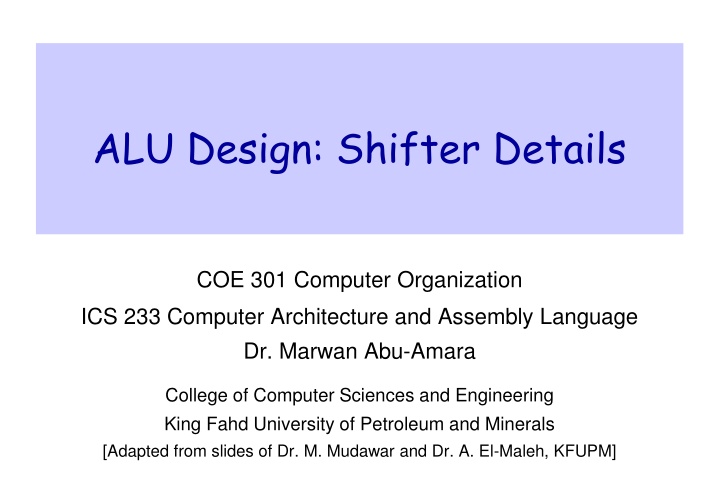
Design and Implementation of Shifters in ALU for Single-Cycle Processors
The detailed discussion covers the construction of a multifunction Arithmetic Logic Unit (ALU) for computer processors, specifically focusing on the design and implementation of shifters. Shift operations such as SLL, SRL, SRA, and ROR are explained, with insights into shifting processes and data extensions. The shifter is implemented using multiplexers and wiring, allowing for versatile shift functionalities. Additionally, the content illustrates how a left logical shift can be achieved by cleverly manipulating the wiring structure of the shifter.

Download Presentation

Please find below an Image/Link to download the presentation.
The content on the website is provided AS IS for your information and personal use only. It may not be sold, licensed, or shared on other websites without obtaining consent from the author.If you encounter any issues during the download, it is possible that the publisher has removed the file from their server.
You are allowed to download the files provided on this website for personal or commercial use, subject to the condition that they are used lawfully. All files are the property of their respective owners.
The content on the website is provided AS IS for your information and personal use only. It may not be sold, licensed, or shared on other websites without obtaining consent from the author.
E N D
Presentation Transcript
ALU Design: Shifter Details COE 301 Computer Organization ICS 233 Computer Architecture and Assembly Language Dr. Marwan Abu-Amara College of Computer Sciences and Engineering King Fahd University of Petroleum and Minerals [Adapted from slides of Dr. M. Mudawar and Dr. A. El-Maleh, KFUPM]
Building a Multifunction ALU 2 Shift/Rotate SLL = 00 SRL = 00 SRA = 01 ROR = 11 SLT: ALU does a SUB and check the sign and overflow Operation 5 Shift Amount Shifter 32 c0 0 ALU Result A 32 sign 32 1 A d d e r 2 B 32 Arithmetic Operation 32 3 ADD = 0 SUB = 1 2 overflow zero ALU 0 Logic Unit Selection 1 Shift = 00 SLT = 01 Arith = 10 Logic = 11 2 AND = 00 OR = 01 NOR = 10 XOR = 11 Operation Logical 3 2 Single Cycle Processor Design COE 301.ICS 233 KFUPM slide 2
Details of the Shifter Implemented with multiplexers and wiring Shift Operation can be: SLL, SRL, SRA, or ROR Input Data is extended to 63 bits according to Shift Op The 63 bits are shifted right according to S4S3S2S1S0 5 sa SLL S4 S3 S2 S1 S0 16 8 4 2 1 0 0 0 0 0 split 63 split 47 split 39 split 35 split 33 Data_out Extender 31 31 31 31 31 32 32 16 31 16 8 4 2 1 Data mux mux mux mux mux 31 8 31 4 31 2 31 1 31 31 31 31 31 1 1 1 1 1 2 1 16 8 4 2 Shift Right 0 or 1 bit Shift Right 0 or 2 bits Shift Right 0 or 4 bits Shift Right 0 or 8 bits Shift Right 0 or 16 bits Shift op Single Cycle Processor Design COE 301.ICS 233 KFUPM slide 3
Details of the Shifter contd Input data is extended from 32 to 63 bits as follows: If shift op = SRL then ext_data[62:0] = 031 || data[31:0] If shift op = SRA then ext_data[62:0] = data[31]31 || data[31:0] If shift op = ROR then ext_data[62:0] = data[30:0] || data[31:0] If shift op = SLL then ext_data[62:0] = data[31:0] || 031 For SRL, the 32-bit input data is zero-extended to 63 bits For SRA, the 32-bit input data is sign-extended to 63 bits For ROR, 31-bit extension = lower 31 bits of data Then, shift right according to the shift amount As the extended data is shifted right, the upper bits will be: 0 (SRL), sign-bit (SRA), or lower bits of data (ROR) Single Cycle Processor Design COE 301.ICS 233 KFUPM slide 4
Implementing Shift Left Logical The wiring of the above shifter dictates a right shift However, we can convert a left shift into a right shift For SLL, 31 zeros are appended to the right of data To shift left by 0 is equivalent to shifting right by 31 To shift left by 1 is equivalent to shifting right by 30 To shift left by 31 is equivalent to shifting right by 0 Therefore, for SLL use the 1 s complement of the shift amount ROL is equivalent to ROR if we use (32 rotate amount) ROL by 10 bits is equivalent to ROR by (32 10) = 22 bits Therefore, software can convert ROL to ROR Single Cycle Processor Design COE 301.ICS 233 KFUPM slide 5