Dealing with Cables, Cavities, and Platform Antennas
Practical solutions for EMC and E3 engineers in dealing with cables, cavities, and platform antennas. Explore cable harness simulation, CAD processing, and simulating antennas with incomplete information to achieve accurate results. Understand the complexities involved in handling real-world cables and the importance of cable model details.
Uploaded on Feb 19, 2025 | 0 Views
Download Presentation

Please find below an Image/Link to download the presentation.
The content on the website is provided AS IS for your information and personal use only. It may not be sold, licensed, or shared on other websites without obtaining consent from the author.If you encounter any issues during the download, it is possible that the publisher has removed the file from their server.
You are allowed to download the files provided on this website for personal or commercial use, subject to the condition that they are used lawfully. All files are the property of their respective owners.
The content on the website is provided AS IS for your information and personal use only. It may not be sold, licensed, or shared on other websites without obtaining consent from the author.
E N D
Presentation Transcript
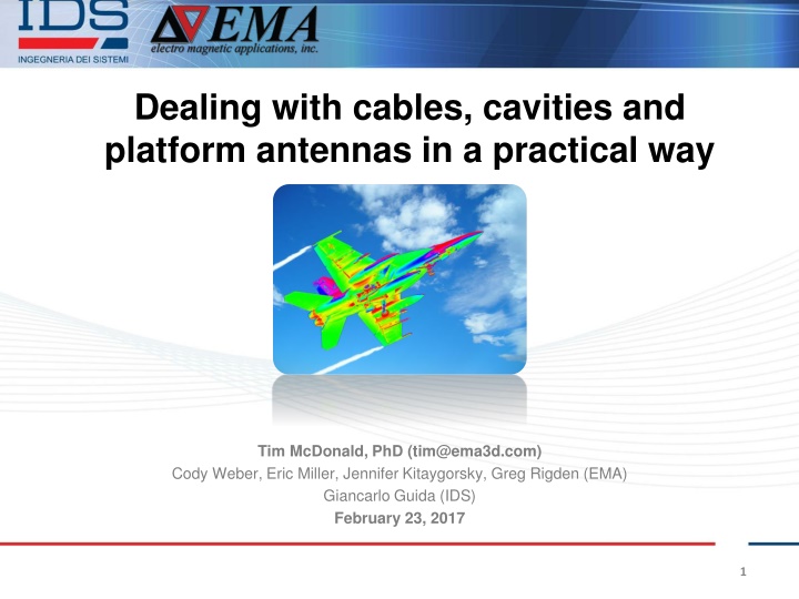
Dealing with cables, cavities and platform antennas in a practical way Tim McDonald, PhD (tim@ema3d.com) Cody Weber, Eric Miller, Jennifer Kitaygorsky, Greg Rigden (EMA) Giancarlo Guida (IDS) February 23, 2017 1
Introduction EMA PhD-level EM Analysts Computational Cluster EM Code Development 39 Years of Experience Labs and Offices in Lakewood, CO (Greater Denver Area) 2
Introduction IDS Founded in 1980 > 500 employees Offices: Italy UK Korea Australia North America 3
Expert training Robust codes Validation heritage on REAL aerospace platforms PhD/Expert simulation concierge support (live, same day) Consulting service teams standing by Lowest cost software tools Custom integrations 4
Practical Solutions for EMC and E3 Engineers Cable harness simulation motivation Cable harness CAD automatic processing Cable harness pre-loaded parameters Simulating antennas with incomplete information Simulating cavity field levels based on power balance Giancarlo Guida (IDS) February 23, 2017 Tim McDonald, PhD (tim@ema3d.com) Cody Weber, Eric Miller, Jennifer Kitaygorsky, Greg Rigden (EMA) 5
Cable harness simulation motivation 6
The Cable Conundrum Classic Cable Simulation Real World Cables Vs. 8
Certain Cable Complexity is Required to Get the Right Answer 10
CEM Model Details Simplified bulk representations of harnesses were initially used in the models The resulting answer diverged from a comparison to testing by 9 dB Initial Bulk Cable Detailed Harness Model Approximate diameter and resistance
Results from More Accurate Harness More accurate harness development in the model also permitted pin voltage calculation and comparison 20 Vmax = 83 t1 = 5.4e-05 t2 = 1.9e-04 0 -20 Voltage [V] -40 -60 -80 -100 Test 17 LTATM Mod 4 -120 0 1 2 3 Time [s] -4 x 10
RF Cable Branching Effect on Coupling to Cables Maximum Current Level (mA per V/m) Current Level Reduction Cable Topology Straight Uniformly Packed Cable 500 Baseline With Branching 30 24 dB The branched cable dissipates nearly all of its energy by 100 s, ten times faster than the cable harness without branches The first vehicle resonance as well as the other modes below 30 MHz have been largely reduced 13
How accurate do we need to be? Some EMC and E3 environments are painful to over- specify requirements Lightning suppression can add significant mass, so more accuracy is needed RF coupling to cables incorrectly may require re-specifying the requirements, new testing and new filters or cable shields 14
The Cable Conundrum The CAD description of cables is incredibly complex Hand simplification takes a long time Making straight lines for cables (too much simplification) gives the wrong answer 15
The Best Solution Automation of simplification for cables Rapid specification of cable harness details based on the wiring diagram Transmission line modeling co- simulated with 3D simulation to resolve branches, shields, and multiple conductors Accelerated methods to speed up calculation 16
Cable harness CAD automatic processing 17
Cable harness pre-loaded parameters 18
What do we need now? Resolve diameter Branches Shields Connection to 3D fields/currents Easy translation from wiring diagram 19
How do we get the harness details into the model? Cable Wiring Diagram Simulation Model 20
Simulation Time Speed-up Via: Numerical techniques Parallelization 21
Simulating antennas with incomplete information 23
Antenna Simulation Near-field antenna levels for EMC Antenna-to-antenna coupling for antenna siting Antenna performance parameters such as gain, directivity or input impedance Rinse-Optimize-Repeat 24
Design Cycle Timeline The optimization steps described above must occur as early as possible 25
What information is available? Unfortunately, the antenna siting and EMC tasks must be completed early in the design cycle But the only information on the antenna design is perhaps its beamwidth and side lobe level 26
Typically Provided Information Tapering (deg.) 3dB beamwidth azimuth plane (deg.) 0.3 3dB beamwidth elevation plane (deg.) 1.5 SLL (dB) 0 -15 18 0.3 5 -15 -18 0.3 5 -15 27
Dealing with Antennas At this point, it is NOT our job to design the antenna because we are the EMC group or the integrator So why use the same tools as an antenna designer? We want to use an equivalent model that makes our life easier 28
How it works We can make an antenna model more robust than the limited information by: Forcing symmetry based on user knowledge of the antenna Interpolating Translating to SWE Using far field in aperture synthesis The generation of models and consistency checking is the most important aspect Training available 29
Platform Modeling With the synthesized antenna model in-hand early, you can proceed with platform modeling Near-field antenna levels for EMC Antenna-to-antenna coupling for antenna siting Antenna performance parameters such as gain, directivity or input impedance Optimization 30
Simulating cavity field levels based on power balance 31
Full Wave Limitations Problem space, or the total number of cells in the problem space, is limited by the memory required to perform computations. The total memory is a trade- off between cell size and volume of the problem space: the smaller the cell size for a given volume, the more memory is required. 32
RE/RS Requirements Requirements up to 18 GHz, and in some cases up to 40 GHz It is difficult to obtain deterministic CEM solutions above ~ 2 GHz (time domain) or the required data spacing in frequency domain simulations Testing is usually done to assess how the RE/RS environment would affect a given spacecraft and its equipment, however, these tests are difficult to perform, expensive, and it can be difficult to determine a worst case environment with the test performed. Testing also does not help with minimizing the costs of the design process. 33
Power Balance Method It can be useful to describe fields statistically. The PWB method is described in detail by Hill [1]. The power can be dissipated by four basic mechanisms: aperture losses, absorption losses, wall losses and antenna losses. [1]. Hill DA (2009) Electromagnetic Fields in Cavities. John Wiley & Sons, Inc., Hoboken, New Jersey 34
OCT Software Module Standard working procedure for em simulation is not required for OCT Topological description Accurate evaluation of Losses Power leakege by apertures Rx power of internal Units Analysis of the CM of an entire vehicle requires seconds ! 35
OCT essentials: Outputs E-Field and Power statistical distribution Un-stirred field conditions in near-region of each interfering source Interference margin for each victim (RS problem) allowing a direct comparison with the corresponding normative Incoming power through each aperture Quality factor for each loss mechanism 36
Validation 37
Scaled Cockpit/Fuselage Model EMA3D Diameter: 1 m Length: 2.5 m Cockpit window: 72 x 32 cm2 Fuselage windows: 20 x 8 cm2 FDTD cell size: 0.5 cm FDTD frequency resolution up to 6 GHz 38
E-Field Inside the Fuselage, 6 GHz: EMA3D 40
EMA3D Comparison to IDS OCT Above HIRF Tray RE/RS and HIRF up to 40 Fast calculation time Previous simulation can GHz give aperture cross sections and power into cavities Extends analysis capabilities 41
Practical Solutions for EMC and E3 Engineers Cable harness simulation motivation Cable harness CAD automatic processing Cable harness pre-loaded parameters Simulating antennas with incomplete information Simulating cavity field levels based on power balance Giancarlo Guida (IDS) February 23, 2017 Tim McDonald, PhD (tim@ema3d.com) Cody Weber, Eric Miller, Jennifer Kitaygorsky, Greg Rigden (EMA) 42
Thanks 43
