DC Circuit: EMFs in Series & Parallel - Charging a Battery
When multiple batteries are connected in series, their voltages add up. Understanding how EMFs work in series and parallel circuits is crucial for efficient charging and discharging. Learn about the total voltage calculation, the wastefulness of opposite direction connections, and the principles behind battery charging. Enhance your knowledge of magnetism, magnetic fields, and the forces exerted on electric currents in this engaging physics lecture.
Download Presentation

Please find below an Image/Link to download the presentation.
The content on the website is provided AS IS for your information and personal use only. It may not be sold, licensed, or shared on other websites without obtaining consent from the author.If you encounter any issues during the download, it is possible that the publisher has removed the file from their server.
You are allowed to download the files provided on this website for personal or commercial use, subject to the condition that they are used lawfully. All files are the property of their respective owners.
The content on the website is provided AS IS for your information and personal use only. It may not be sold, licensed, or shared on other websites without obtaining consent from the author.
E N D
Presentation Transcript
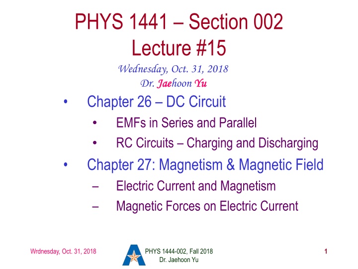
PHYS 1441 Section 002 Lecture #15 Wednesday, Oct. 31, 2018 Dr. Jae Jaehoon Yu Chapter 26 DC Circuit EMFs in Series and Parallel RC Circuits Charging and Discharging Chapter 27: Magnetism & Magnetic Field Electric Current and Magnetism Magnetic Forces on Electric Current Yu Wrdnesday, Oct. 31, 2018 PHYS 1444-002, Fall 2018 Dr. Jaehoon Yu 1
Announcements Reading Assignments: CH26.5, 6 and 7 Reminder: Quiz #3 At the beginning of the class Monday, Nov. 5 Covers CH25.5 to what we learn today (CH27.4?) Bring your calculator but DO NOT input formula into it! Cell phones or any types of computers cannot replace a calculator! BYOF: You may bring a one 8.5x11.5 sheet (front and back) of handwritten formulae and values of constants No derivations, word definitions or solutions of any kind! No additional formulae or values of constants will be provided! 2nd non-comprehensive term exam: Nov. 14 Covers CH25.5 to what we learn Monday, Nov. 12 BYOF Final exam date and time: 11am 2:30pm, Wednesday, Dec. 12 Colloquium today: Dr. D. Winklehner of MIT Wrdnesday, Oct. 31, 2018 PHYS 1444-002, Fall 2018 Dr. Jaehoon Yu 2
Reminder: Special Extra Credit #4 Election Participation Exercise For those with legal voting rights: You can submit three I Voted stickers or the access code green sheet for 20 points total one your own and two others who voted and the remainder 2 points each For those without legal voting rights: You can submit for the first four I Voted sticker or the access code green sheet for 20 points total and the remainder 2 points each Be sure to tape one side of the stickers on a sheet of paper with your name on it. Write the precinct number the vote was cast, the full name of the person voted and the signature of the voter next to the relevant sticker None of the stickers can be from the same person on someone else s extra credit or on your own. All of those with any of the identical persons on your extra credit sheet will get 0 credit. Deadline: Beginning of the class Wednesday, Nov. 7 4
These are acceptable! Wrdnesday, Oct. 31, 2018 PHYS 1444-002, Fall 2018 Dr. Jaehoon Yu 5
EMFs in Series and Parallel: Charging a Battery When two or more sources of emfs, such as batteries, are connected in series The total voltage is the algebraic sum of their voltages, if their direction is the same Vab=1.5 + 1.5=3.0V in figure (a). If the batteries are arranged in the opposite direction, the total voltage is the difference between them Vac=20 12=8.0V in figure (b) Connecting batteries in opposite direction is wasteful. This, however, is the way a battery charger works. Since the 20V battery is at a higher voltage, it forces charges into 12V battery Some battery are rechargeable since their chemical reactions are reversible but most the batteries do not reverse their chemical reactions Parallel arrangements (c) are used only to increase currents. An example? Wrdnesday, Oct. 31, 2018 PHYS 1444-002, Fall 2018 Dr. Jaehoon Yu 6
RC Circuits Circuits containing both resisters and capacitors RC circuits are used commonly in everyday life Control windshield wiper timer Timing of the traffic light Camera flashes and heart pacemakers How does an RC circuit look? There should be a source of emf, capacitors and resisters What happens when the switch S is closed? Current immediately starts flowing through the circuit. Electrons flow out of negative terminal of the emf source, through the resister R and accumulates on the upper plate of the capacitor. The electrons from the bottom plate of the capacitor will flow into the positive terminal of the battery, leaving only positive charge on the bottom plate. As the charge accumulates on the capacitor, the potential difference across it increases The current reduces gradually to 0 till the voltage across the capacitor is the same as emf. The charge on the capacitor increases till it reaches to its maximum CE. Wrdnesday, Oct. 31, 2018 PHYS 1444-002, Fall 2018 Dr. Jaehoon Yu 7
RC Circuits How does all this look like in graphs? The charge and the current on the capacitor as a function of time From energy conservation (Kirchhoff s 2nd rule), the emf Emust be equal to the voltage drop across the capacitor and the resister E=IR+Q/C R includes all resistance in the circuit, including the internal resistance of the battery, I is the current in the circuit at any instance, and Q is the charge of the capacitor at that same instance. Wrdnesday, Oct. 31, 2018 PHYS 1444-002, Fall 2018 Dr. Jaehoon Yu 8
Analysis of RC Circuits ( 1 Q C e ) ( ) In an RC circuit and What can we see from the above equations? Q and VC increase from 0 at t=0 to the maximum value Qmax=CE and VC= E. In how much time? The quantity RC is called the time constant of the circuit, =RC, What is the unit? What is the physical meaning? The time required for a capacitor to reach (1 - e-1)=0.63 or 63% of the full charge dt R t RC t RC = = 1 V e C Sec. I =dQ t RC = e Wrdnesday, Oct. 31, 2018 The current is PHYS 1444-002, Fall 2018 Dr. Jaehoon Yu 9
Example 26 12 RC circuit, with emf. The capacitance in the circuit of the figure is C=0.30 F, the total resistance is 20k , and the battery emf is 12V. Determine (a) the time constant, (b) the maximum charge the capacitor could acquire, (c) the time it takes for the charge to reach 99% of this value, (d) the current I I when the charge Q is half its maximum value, (e) the maximum current, and (f) the charge Q when, the current I I is 0.20 its maximum value. (a) Since = We obtain Q (c) Since Q = 0.01; e = t RC = (d) Since = IR Q C + 0.30 10 6 3 6 3 = 20 10 0.30 10 = 3.6 10 C C = 4.6RC = ) Q C R ) 0.30 10 20 10 3 = ) = 6.0 10 sec RC C = = ( 6 12 = (b) Maximum charge is max t RC C ( ) ) e For 99% we obtain 0.99C = 2ln10; t = I = We obtain I = I = when Q=0: 12 20 10 ( C IR t RC 1 1 e 3 RC t RC 2ln10 ( 28 10 sec ( 4 3 10 A 4 The current when Q is 0.5Qmax (e) When is I maximum? (f) What is Q when I=120mA? Q = 6 6 3 1.8 10 = 12 6 10 A ( ) 12 1.2 10 6 4 4 6 = 2 10 = 10 0.30 10 2.9 10 C Wrdnesday, Oct. 31, 2018 PHYS 1444-002, Fall 2018 Dr. Jaehoon Yu
Discharging RC Circuits When a capacitor is already charged, it is allowed to discharge through a resistance R. When the switch S is closed, the voltage across the resistor at any instant equals that across the capacitor. Thus IR=Q/C. The rate at which the charge leaves the capacitor equals the negative of the current through the resistor I= - dQ/dt This is because the current is leaving the capacitor Thus the voltage equation becomes a differential equation dQR dt C Q dQ Q dt RC = = Rearrange terms Wrdnesday, Oct. 31, 2018 PHYS 1444-002, Fall 2018 Dr. Jaehoon Yu 11
Discharging RC Circuits Now, let s integrate from t=0 when the charge is Q0 to t when the charge is Q Q lnQ Q dQ Q = tdt RC Q = 0 0 t Q Q = The result is Thus, we obtain ln Q RC 0 0 ( ) Q e t RC = Q t 0 What does this tell you about the charge on the capacitor? It decreases exponentially w/ time at the time constant RC Just like the case of charging The current is: I = dt RC What is this? Q dQ ( ) I e t RC 0 = t RC = e I t 0 The current also decreases exponentially w/ time w/ the time constant RC Wrdnesday, Oct. 31, 2018 PHYS 1444-002, Fall 2018 Dr. Jaehoon Yu 12
Example 26 13 Discharging RC circuit. In the RC circuit shown in the figure the battery has fully charged the capacitor, so Q0=CE. Then at t=0, the switch is thrown from position a to b. The battery emf is 20.0V, and the capacitance C=1.02 F. The current I is observed to decrease to 0.50 of its initial value in 40 s. (a) what is the value of R? (b) What is the value of Q, the charge on the capacitor, at t=0? (c) What is Q at t=60 s? (a) Since the current reaches to 0.5 of its initial value in 40 s, we can obtain ( ) 0 I t I e = 0 0 0.5 I For 0.5I I0 I e = = t RC = ln0.5 ln2 t RC t RC Rearrange terms ( ) ( ) 6 6 40 10 = Solve for R 1.02 10 ln2 56.6 = R = ln2 t C (b) The value of Q at t=0 is =C = 620.0 = Q = 1.02 10 20.4 C Q 0 max (c) What do we need to know first for the value of Q at t=60 s? RC = 56.6 1.02 10 Q e = 6 20.4 10 = 60 57.7 s 6 e The RC time Thus ( ) 57.7 t RC s s = = 7.2 = = C 60 Q t s 0 Wrdnesday, Oct. 31, 2018 PHYS 1444-002, Fall 2018 Dr. Jaehoon Yu 13
Application of RC Circuits What do you think the charging and discharging characteristics of RC circuits can be used for? To produce voltage pulses at a regular frequency How? The capacitor charges up to a particular voltage and discharges A simple way of doing this is to use breakdown of voltage in a gas filled tube The discharge occurs when the voltage breaks down at V0 After the completion of discharge, the tube no longer conducts Then the voltage is at V0 and it starts charging up How do you think the voltage as a function of time look? A sawtooth shape Pace maker, intermittent windshield wiper, etc Wrdnesday, Oct. 31, 2018 PHYS 1444-002, Fall 2018 Dr. Jaehoon Yu 14
Magnetism What are magnets? Objects with two poles, North and South poles The pole that points to the geographical North is the North pole and the other is the South pole Principle of compass These are called magnets due to the name of the region, Magnesia, where rocks that attract each other were found What happens when two magnets are brought to each other? They exert force onto each other What kind? Both repulsive and attractive forces depending on the configurations Like poles repel each other while the unlike poles attract Wrdnesday, Oct. 31, 2018 PHYS 1444-002, Fall 2018 Dr. Jaehoon Yu 15
Magnetism So the magnetic poles are the same as the electric charge? No. Why not? While the electric charges (positive and negative) can be isolated, the magnetic poles cannot be isolated. So what happens when a magnet is cut? If a magnet is cut, two magnets are made. The more they get cut, the more magnets are made Single pole magnets are called the monopole but it has not been seen yet Ferromagnetic materials: Materials that show strong magnetic effects Iron, cobalt, nickel, gadolinium and certain alloys Other materials show very weak magnetic effects Wrdnesday, Oct. 31, 2018 PHYS 1444-002, Fall 2018 Dr. Jaehoon Yu 16
