Data Modeling Using the Entity-Relationship (ER) Model
This chapter discusses data modeling using the Entity-Relationship (ER) model, covering concepts such as entities, attributes, relationships, and database design processes. It outlines the design process, entity types, value sets, key attributes, weak entities, and more. The chapter also provides an example of designing a COMPANY database, addressing various requirements for department organization, projects, employees, and dependents.

Download Presentation

Please find below an Image/Link to download the presentation.
The content on the website is provided AS IS for your information and personal use only. It may not be sold, licensed, or shared on other websites without obtaining consent from the author.If you encounter any issues during the download, it is possible that the publisher has removed the file from their server.
You are allowed to download the files provided on this website for personal or commercial use, subject to the condition that they are used lawfully. All files are the property of their respective owners.
The content on the website is provided AS IS for your information and personal use only. It may not be sold, licensed, or shared on other websites without obtaining consent from the author.
E N D
Presentation Transcript
Chapter 3 Data Modeling Using the Entity-Relationship (ER) Model
Outline Overview of Database Design Process Example Database Application (COMPANY) ER Model Concepts Entities and Attributes Entity Types, Value Sets, and Key Attributes Relationships and Relationship Types Weak Entity Types Roles and Attributes in Relationship Types ER Diagrams - Notation ER Diagram for COMPANY Schema
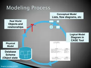
Overview of Database Design Process Database design process involves: Database design Applications design This chapter focuses on conceptual database design to design the conceptual schema for a database application We will use entity-relationship (ER) model Applications design focuses on the programs and interfaces that access the database. This is generally considered part of software engineering
Overview of Overview of Database Design Database Design Process Process
Methodologies for Conceptual Design WE can be able to design conceptual schemas using: Entity Relationship (ER) Diagrams (This Chapter) Enhanced Entity Relationship (EER) Diagrams (Chapter 4) The UML (Unified Modeling Language) Class Diagrams are popular in industry to document conceptual database designs Use of Design Tools in industry for designing and documenting large scale designs
Example COMPANY Database We need to create a database schema design based on the following (simplified) requirements of the COMPANY Database: The company is organized into DEPARTMENTs. Each department has a name, number and an employee who manages the department. We keep track of the start date of the department manager. A department may have several locations. Each department controls a number of PROJECTs. Each project has a unique name, unique number and is located at a single location.
Example COMPANY Database (Continued) The database will store each EMPLOYEE s social security number, address, salary, sex, and birthdate. Each employee works for one department but may work on several projects. The DB will keep track of the number of hours per week that an employee currently works on each project. It is required to keep track of the direct supervisor of each employee. Each employee may have a number of DEPENDENTs. For each dependent, the DB keeps a record of name, sex, birthdate, and relationship to the employee.
ER Model Concepts The ER model describes data as entities, relationships, and attributes
Entities and Attributes Entity is a basic concept for the ER model. Entities are specific things or objects in the mini-world that are represented in the database. For example, the EMPLOYEE John Smith, the Research DEPARTMENT, the ProductX PROJECT Attributes are properties used to describe an entity. For example, an EMPLOYEE entity may have the attributes Name, SSN, Address, Sex, BirthDate A specific entity will have a value for each of its attributes. For example, a specific employee entity may have Name='John Smith', SSN='123456789', Address ='731, Fondren, Houston, TX', Sex='M', BirthDate='09- JAN-55 Each attribute has a value set (or data type) associated with it e.g. integer, string, date, enumerated type,
Types of Attributes Simple (atomic) attribute Each entity has a single atomic value for the attribute. For example, SSN or Sex. Composite attribute The attribute may be composed of several components. For example: Address(Apt#, House#, Street, City, State, ZipCode, Country), or Name(FirstName, MiddleName, LastName). Composition may form a hierarchy where some components are themselves composite.
Types of Attributes (Continued) Single-valued attribute It is an attribute that has a single value for a particular entity. For example, age Multi-valued attribute It is an attribute that can have multiple set of values for a particular entity. For example, Color of a CAR or PreviousDegrees of a STUDENT. Denoted as {Color} or {PreviousDegrees}. Derived Attribute A derived attribute is an attribute whose value can be determined from another related attribute. For example, a person s aga can be determined from date of birth
Types of Attributes (Continued) In general, composite and multi-valued attributes may be nested arbitrarily to any number of levels, although this is rare. For example, PreviousDegrees of a STUDENT is a composite multi-valued attribute denoted by {PreviousDegrees (College, Year, Degree, Field)} Multiple PreviousDegrees values can exist Each has four subcomponent attributes: College, Year, Degree, Field
Entity Types and Key Attributes (1) An entity type defines a collection (or set) of entities that have the same attributes Entities with the same basic attributes are grouped or typed into an entity type. For example, the entity type EMPLOYEE and PROJECT. Each entity type in the database is described by its name and attributes. An entity type usually has one or more attributes whose values are distinct for each individual entity in the entity set. This is called a key attribute. A key attribute is an attribute of an entity type for which each entity must have a unique value. For example, SSN of EMPLOYEE.
Entity Types and Key Attributes (2) A key attribute may be composite. VehicleTagNumber is a key of the CAR entity type with components (Number, State). An entity type may have more than one key. The CAR entity type may have two keys: VehicleIdentificationNumber (popularly called VIN) VehicleTagNumber (Number, State), aka license plate number. Each key is underlined (Note: this is different from the relational schema where only one primary key is underlined).
Entity Set An entity set is a collection of all entities of a particular entity type in the database at any point in time is called an entity set or entity collection. Entity set is also called entity collection Previous slide shows three CAR entity instances in the entity set for CAR Same name (CAR) used to refer to both the entity type and the entity set However, entity type and entity set may be given different names Entity set is the current state of the entities of that type that are stored in the database
Value Sets (Domains) of Attributes Specifies a set of values that may be assigned to that attribute for each individual entity. Each simple attribute is associated with a value set E.g., Lastname has a value which is a character string of upto 15 characters, say Date has a value consisting of MM-DD-YYYY where each letter is an integer A value set specifies the set of values associated with an attribute Value sets are similar to data types in most programming languages e.g., integer, character (n), real, bit
Displaying an Entity type in ER Diagrams In ER diagrams, an entity type is displayed in a rectangular box Attributes are displayed in ovals Each attribute is connected to its entity type Components of a composite attribute are connected to the oval representing the composite attribute Each key attribute is underlined Multivalued attributes displayed in double ovals
NOTATION for NOTATION for ER diagrams ER diagrams
Entity Type CAR Entity Type CAR with two keys with two keys and a and a corresponding corresponding Entity Set Entity Set
Initial Conceptual Design of Entity Types for the COMPANY Database Schema Based on the requirements, we can identify four initial entity types in the COMPANY database: DEPARTMENT PROJECT EMPLOYEE DEPENDENT Their initial conceptual design is shown on the following slide The initial attributes shown are derived from the requirements description
Initial Design of Initial Design of Entity Types: Entity Types: EMPLOYEE, EMPLOYEE, DEPARTMENT, DEPARTMENT, PROJECT, PROJECT, DEPENDENT DEPENDENT
Refining the initial design by introducing relationships ER model has three main concepts: Entities (and their entity types and entity sets) Attributes (simple, composite, multivalued) Relationships (and their relationship types and relationship sets) The initial design is typically not complete Some aspects in the requirements will be represented as relationships We introduce relationship concepts next
Relationships and Relationship Types A relationship relates two or more distinct entities with a specific meaning. For example, EMPLOYEE John Smith works on the ProductX PROJECT, or EMPLOYEE Franklin Wong manages the Research DEPARTMENT. Relationships of the same type are grouped or typed into a relationship type. For example, the WORKS_ON relationship type in which EMPLOYEEs and PROJECTs participate, or the MANAGES relationship type in which EMPLOYEEs and DEPARTMENTs participate. The degree of a relationship type is the number of participating entity types. Both MANAGES and WORKS_ON are binary relationships.
Relationship instances of the WORKS_FOR N:1 relationship between EMPLOYEE and DEPARTMENT
Relationship instances of the M:N WORKS_ON relationship between EMPLOYEE and PROJECT
Relationship type vs. relationship set (1) Relationship Type: Is the schema description of a relationship Identifies the relationship name and the participating entity types Also identifies certain relationship constraints Relationship Set: The current set of relationship instances represented in the database The current state of a relationship type
Relationship type vs. relationship set (2) Previous figures displayed the relationship sets Each instance in the set relates individual participating entities one from each participating entity type In ER diagrams, we represent the relationship type as follows: Diamond-shaped box is used to display a relationship type Connected to the participating entity types via straight lines Note that the relationship type is not shown with an arrow. The name should be typically be readable from left to right and top to bottom.
Refining the COMPANY database schema by introducing relationships By examining the requirements, six relationship types are identified All are binary relationships( degree 2) Listed below with their participating entity types: WORKS_FOR (between EMPLOYEE, DEPARTMENT) MANAGES (also between EMPLOYEE, DEPARTMENT) CONTROLS (between DEPARTMENT, PROJECT) WORKS_ON (between EMPLOYEE, PROJECT) SUPERVISION (between EMPLOYEE (as subordinate), EMPLOYEE (as supervisor)) DEPENDENTS_OF (between EMPLOYEE, DEPENDENT)
ER DIAGRAM Relationship Types are: WORKS_FOR, MANAGES, WORKS_ON, CONTROLS, SUPERVISION, DEPENDENTS_OF
Discussion on Relationship Types In the refined design, some attributes from the initial entity types are refined into relationships: Manager of DEPARTMENT -> MANAGES Works_on of EMPLOYEE -> WORKS_ON Department of EMPLOYEE -> WORKS_FOR etc In general, more than one relationship type can exist between the same participating entity types MANAGES and WORKS_FOR are distinct relationship types between EMPLOYEE and DEPARTMENT Different meanings and different relationship instances.
Constraints on Relationships Constraints on Relationship Types (Also known as ratio constraints) Cardinality Ratio (specifies maximum participation) One-to-one (1:1) One-to-many (1:N) or Many-to-one (N:1) Many-to-many (M:N) Existence Dependency Constraint (specifies minimum participation) (also called participation constraint) zero (optional participation, not existence-dependent) one or more (mandatory participation, existence-dependent)
Recursive Relationship Type A relationship type between the same participating entity type in distinct roles Also called a self-referencing relationship type. Example: the SUPERVISION relationship EMPLOYEE participates twice in two distinct roles: supervisor (or boss) role supervisee (or subordinate) role Each relationship instance relates two distinct EMPLOYEE entities: One employee in supervisor role One employee in supervisee role
Displaying a recursive relationship In a recursive relationship type, both participations are same entity type in different roles. For example, SUPERVISION relationships between EMPLOYEE (in role of supervisor or boss) and (another) EMPLOYEE (in role of subordinate or worker). In ER diagram, need to display role names to distinguish participations.
A Recursive A Recursive Relationship Relationship Supervision Supervision
Recursive Recursive Relationship Relationship Type is: Type is: SUPERVISION SUPERVISION (participation (participation role names are role names are shown) shown)
Weak Entity Types An entity that does not have a key attribute and that is identification- dependent on another entity type. A weak entity must participate in an identifying relationship type with an owner or identifying entity type Entities are identified by the combination of: A partial key of the weak entity type The particular entity they are related to in the identifying relationship type Example: A DEPENDENT entity is identified by the dependent s first name, and the specific EMPLOYEE with whom the dependent is related Name of DEPENDENT is the partial key DEPENDENT is a weak entity type EMPLOYEE is its identifying entity type via the identifying relationship type DEPENDENT_OF
Attributes of Relationship types A relationship type can have attributes: For example, HoursPerWeek of WORKS_ON Its value for each relationship instance describes the number of hours per week that an EMPLOYEE works on a PROJECT. A value of HoursPerWeek depends on a particular (employee, project) combination Most relationship attributes are used with M:N relationships In 1:N relationships, they can be transferred to the entity type on the N-side of the relationship
Example Example Attribute of a Attribute of a Relationship Relationship Type: Hours of Type: Hours of WORKS_ON WORKS_ON
Notation for Constraints on Relationships Cardinality ratio (of a binary relationship): 1:1, 1:N, N:1, or M:N Shown by placing appropriate numbers on the relationship edges. Participation constraint (on each participating entity type): total (called existence dependency) or partial. Total shown by double line, partial by single line. NOTE: These are easy to specify for Binary Relationship Types.
Alternative (min, max) notation for relationship structural constraints: Specified on each participation of an entity type E in a relationship type R Specifies that each entity e in E participates in at least min and at most max relationship instances in R Default(no constraint): min=0, max=n (signifying no limit) Must have min <= max, min>=0, max >= 1 Derived from the knowledge of mini-world constraints Examples: A department has exactly one manager and an employee can manage at most one department. Specify (0,1) for participation of EMPLOYEE in MANAGES Specify (1,1) for participation of DEPARTMENT in MANAGES An employee can work for exactly one department but a department can have any number of employees. Specify (1,1) for participation of EMPLOYEE in WORKS_FOR Specify (0,n) for participation of DEPARTMENT in WORKS_FOR
The (min,max) notation for relationship constraints Read the min,max numbers next to the entity type and looking away from the entity type
COMPANY ER COMPANY ER Schema Schema Diagram Diagram using (min, using (min, max) max) notation notation
Alternative diagrammatic notation ER diagrams is one popular example for displaying database schemas Many other notations exist in the literature and in various database design and modeling tools UML class diagrams is representative of another way of displaying ER concepts that is used in several commercial design tools
Relationships of Higher Degree Relationship types of degree 2 are called binary Relationship types of degree 3 are called ternary and of degree n are called n-ary In general, an n-ary relationship is not equivalent to n binary relationships Constraints are harder to specify for higher-degree relationships (n > 2) than for binary relationships
Discussion of n-ary relationships (n > 2) In general, 3 binary relationships can represent different information than a single ternary relationship If needed, the binary and n-ary relationships can all be included in the schema design ( In some cases, a ternary relationship can be represented as a weak entity if the data model allows a weak entity type to have multiple identifying relationships (and hence multiple owner entity types)
Example of a Example of a ternary ternary relationship relationship


")
")

")
")

 of Attributes")


 Relationship")
 Relationship")


 notation for")
 notation for")