Cryogenics: LN2 Operation in Hall B

Cryogenics – The Basics
Lesson 5
Hall B DBX and Torus - LN2 Operation
D. Kashy

Lesson 5 - Topics
•
LN2 Supply from CHL/ESR
•
ESR Valve Box
•
Hall B Distribution Box (DBX) for LN2 Supply
•
Torus flow paths and controls
•
Return gas to vaporizers and vent
•
What to look for if called in and what to do next
•
Questions
Special NOTES
•
The slides in this presentation are a snapshot in time. They give
general principles of operation.
•
The PID control loop settings may not be up to date so the operators
must use the relevant spread sheets to verify recent and most proper
settings.
•
M:\hallb_eng\CLAS12\Magnets\Operations\Cryogenic Operations
Hall B Torus N2 Operation
•
Liquid Nitrogen is supplied all the way from CHL via the ESTL (end
station transfer line) which has a 4” vacuum jacket and 3”x2.5” IPS
shield circuit that flow LN2. Inside that coaxial line is a 4.5K pipe that
provides 3 atm supercritical helium boost for ESR
•
The LN2 feeds 3 Halls and the ESR cold box
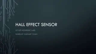
ESR Valve Box
(part 1)
Nitrogen Sub-cooler to
send 4atm liquid at 77K
(subcooled liquid). When it
reaches the Hall it is most
of the time two phase.
4K Return Line with Cold
Return Valve
CEV6721B (must be shut
upon long ESR outages to
facilitate Hall B magnet
recovery
LN2 supply flow meter,
normal is ~0-30g/s)
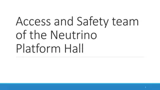
Hall B Distribution
Box (DBX)
Green lines are Nitrogen
lines. Nitrogen is used for
cooling Helium to cool
both the Torus, Solenoid
from 300-80K and for the
Torus shields
3 valves in the DBX are
used during steady state
operation of the entire N2
circuit of Hall B
Geometry is critical in LN2 system
•
The ESR supply is ~20ft above the DBX and the transfer line slopes
down to the Hall.
•
This can and in Hall B does cause the transfer line to be “batch filled”
•
This is because the TL holds a large volume ofLN2 (~250liters)
•
Due to the heat load of the TL and the low use rate in Hall B, the sub-cooling
of the valve box is not enough to keep the gas from boiling.
•
The boil off then occupies the volume that is removed from the bottom of the
reservoir instead of filling it with new cold (subcooled) liquid.
•
This is why the flow rate is not constant
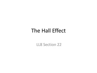
Supply Flow diagram
CFI6751B
TL Volume
250Liters
DBX Reservoir
80 liters
To
HX8558DC
On Catwalk
Then to vent behind ESR
CFI6751B
LL8554CP
DBX LN2 Reservoir Supply Control – EV8553
•
Controls on LN2 level in the reservoir
•
Min is manual at 4.5% provides small
continuous flow
•
Max is 65% sufficient to refill TL
•
This tune works for Steady State, Cool down
and Parking!
DBX LN2 Reservoir Pressure Control – PV8558
•
Controls on pressure in the reservoir at 1.5 atm,
•
Min is manual at 1% provides small continuous flow and helps not to get
stuck
•
Max is 100 % sufficient to refill TL, typically opens to ~80% during batch fill
•
This tune works for Steady State and Parking, during 300K -80K shield cool
down we ran it at 1.7 atm
DBX LN2 Reservoir Heater Control – HTR8554
•
Controls on pressure in the reservoir at 1.1 atm,
•
Min is zero and max is 40% The purpose is to
assure we have flow in the vent line to keep the
N2 system clean. (It does not come on- WHY?)
•
This heater can also be used to boil LN2 during
shield cool down from 300K (off topic here)
Torus Nitrogen supply Control – EV8555T
•
High pressure (4atm) nitrogen (gas or liquid) at ~92K goes through a coil in the reservoir
•
It is condensed or just cooled into sub-cooled liquid at ~4atm and 82K
•
EV8555T supplies the liquid to the Torus based on supply temperature and liquid level
•
Min PID controls on maximum allowable supply temperature at 92K to keep the U-tube from
warming too much
•
Primary loop controls on Reservoir Level in the Torus (next slide)
•
This tune works for Steady State and Parking, Shield in Torus always runs unless warming to 300K!
Torus Nitrogen cooled radiation shields
•
LN2 is supplied to the
shields below a check
valve under the reservoir
•
This allows cool down w/o
an extra valve
•
Cooling was to be a
thermosiphon, but works
like forced flow with batch
fill of tubes and reservoir
•
Nitrogen vent goes
through the DBX directly
to the vaporizer HX8558M
on the North side of Hall B
then to atmosphere via
check valve outside ESR
through same 4” line as
DBX vent
Typical parameters of N2 shield control
Torus Nitrogen cooled radiation shields - Details
•
8 parallel circuits each
with its own return to
the reservoir
•
Coil C operates warmer
than the others, but this
has not bothered the 4K
operation or powering
the magnet
•
Coil E showed similar
warming during summer
2018 for a brief period
but recovered
•
When magnet 4K is off
the shields all cool off to
77K outlets
Supply Controls –
EV8111CD
What to look for and do if called in
•
Check levels in DBX and Torus
•
Check to see trends of temperatures and valve positions
•
Go to Hall and look at vacuums of TL, DBX and U-tubes
•
Make sure vacuum pumps on Torus are running and vacuums are
good
•
Call in experts if nothing can be found
N2 Summary
•
Not working quite as designed, BUT does work well!
•
No changes observed during any fast dumps
•
No tuning of PID loops has been required for nearly 1 year
Questions?
Dive into the basics of operating liquid nitrogen (LN2) systems in Hall B, focusing on topics such as LN2 supply, distribution boxes, ESR valve control, and system geometries. Learn about the critical components and operational considerations for efficient LN2 utilization.

Download Presentation

Please find below an Image/Link to download the presentation.
The content on the website is provided AS IS for your information and personal use only. It may not be sold, licensed, or shared on other websites without obtaining consent from the author.If you encounter any issues during the download, it is possible that the publisher has removed the file from their server.
You are allowed to download the files provided on this website for personal or commercial use, subject to the condition that they are used lawfully. All files are the property of their respective owners.
The content on the website is provided AS IS for your information and personal use only. It may not be sold, licensed, or shared on other websites without obtaining consent from the author.
E N D
Presentation Transcript
Cryogenics The Basics Lesson 5 Hall B DBX and Torus - LN2 Operation D. Kashy
Lesson 5 - Topics LN2 Supply from CHL/ESR ESR Valve Box Hall B Distribution Box (DBX) for LN2 Supply Torus flow paths and controls Return gas to vaporizers and vent What to look for if called in and what to do next Questions
Special NOTES The slides in this presentation are a snapshot in time. They give general principles of operation. The PID control loop settings may not be up to date so the operators must use the relevant spread sheets to verify recent and most proper settings. M:\hallb_eng\CLAS12\Magnets\Operations\Cryogenic Operations
Hall B Torus N2 Operation Liquid Nitrogen is supplied all the way from CHL via the ESTL (end station transfer line) which has a 4 vacuum jacket and 3 x2.5 IPS shield circuit that flow LN2. Inside that coaxial line is a 4.5K pipe that provides 3 atm supercritical helium boost for ESR The LN2 feeds 3 Halls and the ESR cold box
ESR Valve Box (part 1) Nitrogen Sub-cooler to send 4atm liquid at 77K (subcooled liquid). When it reaches the Hall it is most of the time two phase. LN2 supply flow meter, normal is ~0-30g/s) 4K Return Line with Cold Return Valve CEV6721B (must be shut upon long ESR outages to facilitate Hall B magnet recovery
Hall B Distribution Box (DBX) Green lines are Nitrogen lines. Nitrogen is used for cooling Helium to cool both the Torus, Solenoid from 300-80K and for the Torus shields 3 valves in the DBX are used during steady state operation of the entire N2 circuit of Hall B
Geometry is critical in LN2 system The ESR supply is ~20ft above the DBX and the transfer line slopes down to the Hall. This can and in Hall B does cause the transfer line to be batch filled This is because the TL holds a large volume ofLN2 (~250liters) Due to the heat load of the TL and the low use rate in Hall B, the sub-cooling of the valve box is not enough to keep the gas from boiling. The boil off then occupies the volume that is removed from the bottom of the reservoir instead of filling it with new cold (subcooled) liquid. This is why the flow rate is not constant
Supply Flow diagram TL Volume 250Liters CFI6751B To HX8558DC On Catwalk Then to vent behind ESR CFI6751B EV8553 DBX Reservoir 80 liters LL8554CP
DBX LN2 Reservoir Supply Control EV8553 Controls on LN2 level in the reservoir Min is manual at 4.5% provides small continuous flow Max is 65% sufficient to refill TL This tune works for Steady State, Cool down and Parking!
DBX LN2 Reservoir Pressure Control PV8558 Controls on pressure in the reservoir at 1.5 atm, Min is manual at 1% provides small continuous flow and helps not to get stuck Max is 100 % sufficient to refill TL, typically opens to ~80% during batch fill This tune works for Steady State and Parking, during 300K -80K shield cool down we ran it at 1.7 atm
DBX LN2 Reservoir Heater Control HTR8554 Controls on pressure in the reservoir at 1.1 atm, Min is zero and max is 40% The purpose is to assure we have flow in the vent line to keep the N2 system clean. (It does not come on- WHY?) This heater can also be used to boil LN2 during shield cool down from 300K (off topic here)
Torus Nitrogen supply Control EV8555T High pressure (4atm) nitrogen (gas or liquid) at ~92K goes through a coil in the reservoir It is condensed or just cooled into sub-cooled liquid at ~4atm and 82K EV8555T supplies the liquid to the Torus based on supply temperature and liquid level Min PID controls on maximum allowable supply temperature at 92K to keep the U-tube from warming too much Primary loop controls on Reservoir Level in the Torus (next slide) This tune works for Steady State and Parking, Shield in Torus always runs unless warming to 300K!
Torus Nitrogen cooled radiation shields LN2 is supplied to the shields below a check valve under the reservoir This allows cool down w/o an extra valve Cooling was to be a thermosiphon, but works like forced flow with batch fill of tubes and reservoir Nitrogen vent goes through the DBX directly to the vaporizer HX8558M on the North side of Hall B then to atmosphere via check valve outside ESR through same 4 line as DBX vent
Torus Nitrogen cooled radiation shields - Details 8 parallel circuits each with its own return to the reservoir Coil C operates warmer than the others, but this has not bothered the 4K operation or powering the magnet Coil E showed similar warming during summer 2018 for a brief period but recovered When magnet 4K is off the shields all cool off to 77K outlets
Supply Controls EV8111CD
What to look for and do if called in Check levels in DBX and Torus Check to see trends of temperatures and valve positions Go to Hall and look at vacuums of TL, DBX and U-tubes Make sure vacuum pumps on Torus are running and vacuums are good Call in experts if nothing can be found
N2 Summary Not working quite as designed, BUT does work well! No changes observed during any fast dumps No tuning of PID loops has been required for nearly 1 year