Hall Effect in Magnetic Sensors
The Hall effect, discovered by Edwin Hall in 1879, is utilized in magnetic sensors to detect magnetic fields by measuring the Lorentz force on moving charges. Hall sensors generate a Hall voltage based on the positive and negative charge carriers present. Integrated Hall sensors provide detailed specifications for measuring magnetic fields and offer insights into applications like electronic compasses. Despite their utility, challenges arise in achieving the required accuracy due to factors such as amplifier contributions and noise interference.

Download Presentation

Please find below an Image/Link to download the presentation.
The content on the website is provided AS IS for your information and personal use only. It may not be sold, licensed, or shared on other websites without obtaining consent from the author.If you encounter any issues during the download, it is possible that the publisher has removed the file from their server.
You are allowed to download the files provided on this website for personal or commercial use, subject to the condition that they are used lawfully. All files are the property of their respective owners.
The content on the website is provided AS IS for your information and personal use only. It may not be sold, licensed, or shared on other websites without obtaining consent from the author.
E N D
Presentation Transcript
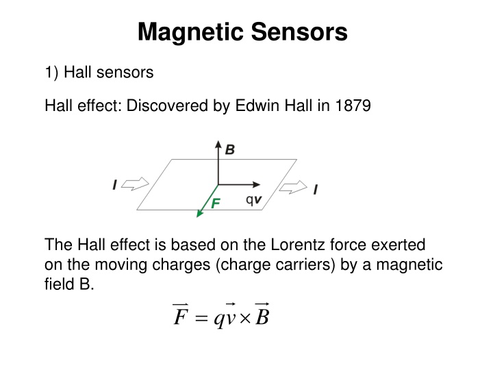
Magnetic Sensors 1) Hall sensors Hall effect: Discovered by Edwin Hall in 1879 The Hall effect is based on the Lorentz force exerted on the moving charges (charge carriers) by a magnetic field B. F qv B =
Generation of the Hall voltage VH Negative charge carriers Positive charge carriers
Integrated Hall Sensors Ibias V Gr nqt = = S I H H VH+ VH- A bias B R0=2.2 k SA=0.0412 V/T for Ibias=0.5 mA
Ex. 1: Electronic Compass Earth s Magnetic Field Intensity : 25-65 T (0.25 0.65 G) Horizontal component in Pisa (from map) 23300 nT ~ 23 T
Sensor arrangement: Two orhogonal sensors that measure the X and Y components (horizontal components) of the magnetic field B BY BX B = e Angular resolution: e B H Let us consider a maximum error of 5 : 5 e = = . 0 087 rad 180 ( ) ( ) = = 0.087 23.3 10 6 max max T 2 T B B e e H
Amplifier contribution to the angular error AD 620 IBIAS=0.5 mA SA=VH/B=0.0412 V/T for B=23 T : VH 0.95 V G=1000 EF ( ) R = + v v R i i R = 0 1.1k 1 2 nt n S B B S 2 OFFSET: affects the accuracy V = + = + io tot v v R i OSO G v V io S io io OSI 6 200 10 1000 = 15 10 + 15 V 6 io v VOSI=15 V VOSO= 200 V (typical) Offset current contribution: IioRS= 0.3 nA x 1.1 k =0.33 V << Vio-total
Offset referred to the measured magnetic field: = = = 6 io tot v S 15 10 0.0412 364 T B io A The equivalent offset in the magnetic field measurement is much larger than the requirement (2 T), Then the accuracy of this combination of sensor and in-amp is not adequate for an electronic compass Let us see what we may expect in terms of resolution Noise: BW 0.1-100 Hz Broad Band noise: eni= SVBB=9 nV Hz Integrated over BW=100Hz: vnBB-rms=90 nV -> vnBB-pp=360 nV Even considering only the contribution of the input noise voltage source, also the resolution is worse than required Low frequency (Flicker) noise over 0.1-10 Hz -> 280 nV Total noise voltage of the amplifier: = + = 2 nBB 2 nF 11 T 456 nV v v v nA pp pp pp
Amplifier contribution to the angular error (2) Current noise: Broad-band component R 2 = = 1 . 1 = 2 0 2 k S S R R VI I S S S R 0 I = = 100 fA / Hz S S VI I 2 = . 0 155 nV / S Hz VI Flicker component: R = 0= 22 nV v i ni f pp n pp 2 Noise voltage components due to the input bias current noise are negligible with respect to the input noise voltage components.
Sensor intrinsic offset Bio 25 T Bio<5 T (between 25 and 35 C) Bio(T) since 2 T -> 5 angular error then: Offset: -> 61 angular error Drift: -> 12 angular error Even considering only the offset of the sensor, specs are not satisfied
Typical readout approach for precise measurements: Current Spinning Ibias 2 1 3 4


")