Caterpillar Cat D6R TRACK TRACTOR (Prefix 7GR) Service Repair Manual Instant Download
Please open the website below to get the complete manualnn// n
Download Presentation

Please find below an Image/Link to download the presentation.
The content on the website is provided AS IS for your information and personal use only. It may not be sold, licensed, or shared on other websites without obtaining consent from the author. Download presentation by click this link. If you encounter any issues during the download, it is possible that the publisher has removed the file from their server.
E N D
Presentation Transcript
Service Repair Manual Models D6R TRACK TRACTOR
D6R Track-Type Tractor Differential Steering 7GR00001-UP (MACHINE) POWERE... 1/4 Shutdown SIS Previous Screen Product: TRACK-TYPE TRACTOR Model: D6R TRACK-TYPE TRACTOR 7GR Configuration: D6R Track-Type Tractor Differential Steering 7GR00001-UP (MACHINE) POWERED BY 3306 Engine Disassembly and Assembly D6R TRACK-TYPE TRACTOR POWER TRAIN Media Number -SENR9496-02 Publication Date -01/11/2004 Date Updated -23/07/2018 SENR94960032 Final Drive, Planetary And Brake (Right Side) SMCS - 4132-010 Remove And Install Right Final Drive, Planetary And Brake Start By: a. separate track (right side) Before doing any service work which requires separating a track, a thorough inspection of the front track roller frame must be made. See Special Instruction, Form No. SMHS8273-02. 1. Remove the drain plug from the transmission and bevel gear case, and drain the power train oil. Install the drain plug. https://127.0.0.1/sisweb/sisweb/techdoc/techdoc_print_page.jsp?returnurl=/sisw... 2019/9/1
D6R Track-Type Tractor Differential Steering 7GR00001-UP (MACHINE) POWERE... 2/4 2. Turn the final drive until drain plug (2) is on the bottom as shown. Remove drain plug (2), and drain the oil from the final drive. Install the drain plug. 3. Remove the three bolts and cover (1) from the final drive. Remove the O-ring seal from the cover. 4. Install Tooling (A) and remove outer axle (3). 5. Adjust the top bracket on Tooling (B) so that dimension (X) is 165 mm (6.5 in.). The lower mounting bracket must be installed with the spacers outward as shown. https://127.0.0.1/sisweb/sisweb/techdoc/techdoc_print_page.jsp?returnurl=/sisw... 2019/9/1
https://www.ebooklibonline.com Hello dear friend! Thank you very much for reading. Enter the link into your browser. The full manual is available for immediate download. https://www.ebooklibonline.com
D6R Track-Type Tractor Differential Steering 7GR00001-UP (MACHINE) POWERE... 3/4 6. Remove two of the bolts from the sprocket segment. Fasten a hoist and Tooling (B) on the final drive. NOTICE Do not remove two bolts (5) that hold the final drive to the planetary and brake. 7. Remove twenty six bolts (4) that hold the final drive, planetary and brake to the frame. 8. Remove two bolts (6) that hold the planetary and brake to the frame. 9. Using Tooling (B) and hoist, remove the final drive, planetary and brake as a unit. The weight of the final drive, planetary and brake assembly is 577 kg (1270 lb.). 10. Remove O-ring seals (7) and (8) from the planetary and brake housing. NOTE: The following steps are for installation of the right final drive, planetary and brake. 11. Install O-ring seals (7) and (8) on the planetary and brake housing. Put clean oil on the O-ring seals. 12. Fasten a hoist and Tooling (B) on the final drive. Make an adjustment to Tooling (B) if needed, to level the final drive, planetary and brake. 13. Put the final drive, planetary and brake in position on the tractor. 14. Install two bolts (6) that hold the planetary and brake in position on the frame. https://127.0.0.1/sisweb/sisweb/techdoc/techdoc_print_page.jsp?returnurl=/sisw... 2019/9/1
D6R Track-Type Tractor Differential Steering 7GR00001-UP (MACHINE) POWERE... 4/4 15. Install twenty six bolts (4), and remove the hoist and Tooling (B). 16. Put SAE 30W oil on the threads of the two segment bolts, and install the two bolts, washers and nuts. Tighten the nuts to a torque of 175 40 N m (130 30 lb.ft.). Tighten the nuts 1/3 of a turn more. 17. Using Tooling (A), install outer axle (3). 18. Install the O-ring seal on cover (1). Put cover (1) in position on the final drive, and install the three bolts. 19. Fill the final drive with oil to the correct level. See the Operation And Maintenance Manual. 20. Fill the transmission and bevel gear case with oil to the correct level. See the Operation And Maintenance Manual. End By: a. connect track (right side) Copyright 1993 - 2019 Caterpillar Inc. Sun Sep 1 15:13:23 UTC+0800 2019 All Rights Reserved. Private Network For SIS Licensees. https://127.0.0.1/sisweb/sisweb/techdoc/techdoc_print_page.jsp?returnurl=/sisw... 2019/9/1
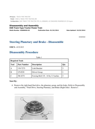
D6R Track-Type Tractor Differential Steering 7GR00001-UP (MACHINE) POWERE... 1/9 Shutdown SIS Previous Screen Product: TRACK-TYPE TRACTOR Model: D6R TRACK-TYPE TRACTOR 7GR Configuration: D6R Track-Type Tractor Differential Steering 7GR00001-UP (MACHINE) POWERED BY 3306 Engine Disassembly and Assembly D6R TRACK-TYPE TRACTOR POWER TRAIN Media Number -SENR9496-02 Publication Date -01/11/2004 Date Updated -23/07/2018 SENR94960033 Right Planetary And Brake SMCS - 4132-015; 4132-016 Disassemble Right Planetary And Brake Start By: a. remove final drive, planetary and brake (right side) 1. Position the right final drive, planetary and brake as shown. 2. Remove the two forcing screws and nuts that fasten right planetary and brake (1) to final drive (2). The two forcing screws and nuts were installed during the removal of the right final drive, planetary and brake. 3. Attach Tooling (A) and a hoist to right planetary and brake (1). Install three 3/8 in - 16 NC forcing screws in the final drive hub. Tighten the forcing screws evenly, and remove right planetary and brake (1) from final drive (2). The weight of the right planetary and brake is 136 kg (300 lb.). https://127.0.0.1/sisweb/sisweb/techdoc/techdoc_print_page.jsp?returnurl=/sisw... 2019/9/1
D6R Track-Type Tractor Differential Steering 7GR00001-UP (MACHINE) POWERE... 2/9 NOTICE Remove bolts (3) evenly to relieve the spring pressure behind gear (4). 4. Remove bolts (3), and remove gear (4) from housing (5). 5. Remove four discs (6) and the three plates from the housing. NOTICE Do not let planetary carrier (10) fall when it is pressed from housing (5). https://127.0.0.1/sisweb/sisweb/techdoc/techdoc_print_page.jsp?returnurl=/sisw... 2019/9/1
D6R Track-Type Tractor Differential Steering 7GR00001-UP (MACHINE) POWERE... 3/9 6. Remove bolts (7) and plate (8). Use a press and Tooling (B) to remove planetary carrier (10) from housing (5). 7. Remove bearing cone (9) from the housing. 8. Remove ring (14) from carrier (11). 9. Remove bolts (13), and remove slinger (12) from the carrier. NOTICE Bearing cone (15) must be destroyed to remove it from the carrier. 10. If necessary, remove bearing cone (15) from carrier (11). 11. Use a hammer and punch to push pin (17) in shaft (16). 12. Remove shaft (16), gear (19), two discs (20) and two bearings (21) from carrier (11). 13. Remove pin (17) from shaft (16). https://127.0.0.1/sisweb/sisweb/techdoc/techdoc_print_page.jsp?returnurl=/sisw... 2019/9/1
D6R Track-Type Tractor Differential Steering 7GR00001-UP (MACHINE) POWERE... 4/9 14. Remove the remaining two gears. 15. Remove gear assembly (18) from carrier (11). NOTICE Remove bolts (22) evenly to relieve the spring pressure behind retainer (23). 16. Remove bolts (22), and remove retainer (23) from piston (24). 17. If necessary, remove bearing cups (25) from retainer (23). 18. Remove seal ring (26) from the retainers. 19. Remove piston (24) and O-ring seal (27) from the housing. https://127.0.0.1/sisweb/sisweb/techdoc/techdoc_print_page.jsp?returnurl=/sisw... 2019/9/1
D6R Track-Type Tractor Differential Steering 7GR00001-UP (MACHINE) POWERE... 5/9 20. Remove seal ring (28) from piston (24). 21. If necessary, remove ring (29) from piston (24). 22. Remove spring (30) and ring (31) from housing (5). Assemble Right Planetary And Brake 1. Put ring (31) and spring (30) in position in housing (5). Spring (30) must be installed with the convex side up. https://127.0.0.1/sisweb/sisweb/techdoc/techdoc_print_page.jsp?returnurl=/sisw... 2019/9/1
D6R Track-Type Tractor Differential Steering 7GR00001-UP (MACHINE) POWERE... 6/9 2. Install ring (29) on piston (24). 3. Install seal ring (28) in piston (24). Install seal ring (28) with the lip of the seal ring as shown. Put clean oil on the seal ring. 4. Install piston (24) and O-ring seal (27) in the housing. 5. If bearing cups (25) were removed, lower the temperature of the bearing cups, and install them in retainer (23). 6. Install seal ring (26) in retainer (23). Install seal ring with the lip of the seal ring as shown. Put clean oil on the seal ring. 7. Position retainer (23) on piston (24). Make sure the oil passage in retainer (23) is aligned with the oil passage and O-ring seal in the housing. Install bolts (22) that hold retainer (23) in place. https://127.0.0.1/sisweb/sisweb/techdoc/techdoc_print_page.jsp?returnurl=/sisw... 2019/9/1
D6R Track-Type Tractor Differential Steering 7GR00001-UP (MACHINE) POWERE... 7/9 8. Position gear assembly (18) in carrier (11). 9. Install two bearings (21) in gear (19). 10. Put discs (20) and gear (19) in position in carrier (11), and install shaft (16). NOTE: Make sure the rubbers in pin (17) is not damaged. If the rubber in the pin is damaged, replace the pin. 11. Align the hole in shaft (16) with the hole in carrier (11), and install pin (17). Install the pin until it is even with the surface of the carrier. 12. Install the remaining two gears in the carrier. NOTE: If bearing cone (15) was removed from carrier (11), a new bearing must be installed. 13. Heat bearing cone (15) to a maximum temperature of 135 C (275 F). Install the bearing cone or carrier (11). Make sure the bearing cone is seated on the carrier. 14. Coat the flange of slinger (12) which contacts carrier (11) with 8C8422 sealant. Put slinger (12) in position on carrier (11), and install bolts (13). 15. Install ring (14) in carrier (11). 16. Position housing (5) on carrier (11). https://127.0.0.1/sisweb/sisweb/techdoc/techdoc_print_page.jsp?returnurl=/sisw... 2019/9/1
D6R Track-Type Tractor Differential Steering 7GR00001-UP (MACHINE) POWERE... 8/9 17. Heat bearing cone (9) to a maximum temperature of 135 C (275 F), and install, the bearing cone on carrier (11). 18. Position plate (8) on the carrier, and install bolts (7). 19. Start with a disc, and install four discs (6) and the three plates. Alternate the discs and plates. 20. Position gear (4) on housing (5), and install bolts (3). 21. Use a hoist and Tooling (A) to position right planetary and brake (1) on final drive (2). Install the two bolts that fasten the right planetary and brake on the final drive. End By: a. install final drive, planetary and brake (right side) Sun Sep 1 15:14:08 UTC+0800 2019 https://127.0.0.1/sisweb/sisweb/techdoc/techdoc_print_page.jsp?returnurl=/sisw... 2019/9/1
D6R Track-Type Tractor Differential Steering 7GR00001-UP (MACHINE) POWERE... 9/9 Copyright 1993 - 2019 Caterpillar Inc. All Rights Reserved. Private Network For SIS Licensees. https://127.0.0.1/sisweb/sisweb/techdoc/techdoc_print_page.jsp?returnurl=/sisw... 2019/9/1
D6R Track-Type Tractor Differential Steering 7GR00001-UP (MACHINE) POWERE... 1/6 Shutdown SIS Previous Screen Product: TRACK-TYPE TRACTOR Model: D6R TRACK-TYPE TRACTOR 7GR Configuration: D6R Track-Type Tractor Differential Steering 7GR00001-UP (MACHINE) POWERED BY 3306 Engine Disassembly and Assembly D6R Track-Type Tractor Machine Systems Media Number -SENR9488-01 Publication Date -01/02/2002 Date Updated -14/02/2002 i01007311 Bulldozer Blade - Remove and Install SMCS - 6060-010 Removal Procedure Table 1 Required Tools Tool Part Number Part Description Qty A 1U-9759 Stand (pair) 1 Personal injury can result from hydraulic oil pressure and hot oil. Hydraulic oil pressure can remain in the hydraulic system after the engine has been stopped. Serious injury can be caused if this pressure is not released before any service is done on the hydraulic system. Make sure all of the attachments have been lowered, oil is cool before removing any components or lines. Remove the oil filler cap only when the engine is stopped, and the filler cap is cool enough to touch with your bare hand. NOTICE Care must be taken to ensure that fluids are contained during performance of inspection, maintenance, testing, adjusting and repair https://127.0.0.1/sisweb/sisweb/techdoc/techdoc_print_page.jsp?returnurl=/sisw... 2019/9/1
D6R Track-Type Tractor Differential Steering 7GR00001-UP (MACHINE) POWERE... 2/6 of the product. Be prepared to collect the fluid with suitable containers before opening any compartment or disassembling any component containing fluids. Refer to Special Publication, NENG2500, "Caterpillar Tools and Shop Products Guide" for tools and supplies suitable to collect and contain fluids on Caterpillar products. Dispose of all fluids according to local regulations and mandates. Note: Mark all components for correct installation. When you disconnect the hoses, cap the connections in order to keep the system clean. Illustration 1 g00596992 1. Disconnect hose assemblies (2) from manifold (1) . Illustration 2 g00596999 2. Remove the following components from the lift cylinders: bolts (3), cap (5) and shims (4). Retract the lift cylinders. https://127.0.0.1/sisweb/sisweb/techdoc/techdoc_print_page.jsp?returnurl=/sisw... 2019/9/1
D6R Track-Type Tractor Differential Steering 7GR00001-UP (MACHINE) POWERE... 3/6 Illustration 3 g00597001 3. Remove the following components from the stabilizer link: bolts (8), cap (6) and shims (7) . Illustration 4 g00597003 4. Install Tooling (A) under each push arm (9), as shown. https://127.0.0.1/sisweb/sisweb/techdoc/techdoc_print_page.jsp?returnurl=/sisw... 2019/9/1
D6R Track-Type Tractor Differential Steering 7GR00001-UP (MACHINE) POWERE... 4/6 Illustration 5 g00597004 5. Remove the following components from each push arm: bolts (12), cap (11) and shims (10) . Illustration 6 g00597006 6. Secure stabilizer link (14) to bulldozer blade (13). Move the machine away from the bulldozer blade. Installation Procedure Table 2 Required Tools Tool Part Number Part Description Qty A 1U-9759 Stand (pair) 1 Reference: Refer to Specifications, "Push Arm" in the Service Manual for your machine. Illustration 7 g00597006 https://127.0.0.1/sisweb/sisweb/techdoc/techdoc_print_page.jsp?returnurl=/sisw... 2019/9/1
D6R Track-Type Tractor Differential Steering 7GR00001-UP (MACHINE) POWERE... 5/6 1. Move the machine to bulldozer blade (13), as shown. Illustration 8 g00597004 2. Connect each push arm to the trunnion on the track roller frame by installing the following components: shims (10), cap (11) and bolts (12). Tighten the bolts to a torque of 1800 200 N m (1300 150 lb ft). Illustration 9 g00597001 3. Connect the stabilizer link to the trunnion on the machine by installing the following components: shims (7), cap (6) and bolts (8). Tighten the bolts to a torque of 430 60 N m (320 45 lb ft). https://127.0.0.1/sisweb/sisweb/techdoc/techdoc_print_page.jsp?returnurl=/sisw... 2019/9/1
D6R Track-Type Tractor Differential Steering 7GR00001-UP (MACHINE) POWERE... 6/6 Illustration 10 g00596999 4. Extend the lift cylinders to the trunnion on the bulldozer blade. Connect each lift cylinder to a trunnion on the bulldozer blade by installing the following components: shims (4), cap (5) and bolts (3). Tighten the bolts to a torque of 430 60 N m (320 45 lb ft). Illustration 11 g00596992 5. Connect hose assemblies (2) to manifold (1). Tighten the bolts on the half flanges to a torque of 50 10 N m (37 7 lb ft). 6. Operate the lift cylinders for several cycles in order to purge air from the system. Fill the hydraulic tank. Reference: Refer to the Operation and Maintenance Manual, "Lubricant Viscosities and Refill Capacities" for your machine. Copyright 1993 - 2019 Caterpillar Inc. Sun Sep 1 16:51:02 UTC+0800 2019 All Rights Reserved. Private Network For SIS Licensees. https://127.0.0.1/sisweb/sisweb/techdoc/techdoc_print_page.jsp?returnurl=/sisw... 2019/9/1
D6R Track-Type Tractor Differential Steering 7GR00001-UP (MACHINE) POWERE... 1/3 Shutdown SIS Previous Screen Product: TRACK-TYPE TRACTOR Model: D6R TRACK-TYPE TRACTOR 7GR Configuration: D6R Track-Type Tractor Differential Steering 7GR00001-UP (MACHINE) POWERED BY 3306 Engine Disassembly and Assembly D6R Track-Type Tractor Machine Systems Media Number -SENR9488-01 Publication Date -01/02/2002 Date Updated -14/02/2002 i01007322 Bulldozer Lift Cylinder - Remove SMCS - 5102-011 Removal Procedure Table 1 Required Tools Tool Part Number Part Description Qty A 138-7573 Link Bracket 2 Personal injury can result from hydraulic oil pressure and hot oil. Hydraulic oil pressure can remain in the hydraulic system after the engine has been stopped. Serious injury can be caused if this pressure is not released before any service is done on the hydraulic system. Make sure all of the attachments have been lowered, oil is cool before removing any components or lines. Remove the oil filler cap only when the engine is stopped, and the filler cap is cool enough to touch with your bare hand. NOTICE Care must be taken to ensure that fluids are contained during performance of inspection, maintenance, testing, adjusting and repair https://127.0.0.1/sisweb/sisweb/techdoc/techdoc_print_page.jsp?returnurl=/sisw... 2019/9/1
D6R Track-Type Tractor Differential Steering 7GR00001-UP (MACHINE) POWERE... 2/3 of the product. Be prepared to collect the fluid with suitable containers before opening any compartment or disassembling any component containing fluids. Refer to Special Publication, NENG2500, "Caterpillar Tools and Shop Products Guide" for tools and supplies suitable to collect and contain fluids on Caterpillar products. Dispose of all fluids according to local regulations and mandates. Note: Mark all components for correct installation. When you disconnect the hoses, cap the connections in order to keep the system clean. Illustration 1 g00613170 1. Remove bolts (1) with the nuts. Remove cap (3) with the shims from the cylinder rod. 2. Move the cylinder rod into the lift cylinder and away from bulldozer blade trunnion (2) . 3. Place cap (3) with the shims on the cylinder rod. Loosely install bolts (1) with the nuts. Illustration 2 g00584779 https://127.0.0.1/sisweb/sisweb/techdoc/techdoc_print_page.jsp?returnurl=/sisw... 2019/9/1
D6R Track-Type Tractor Differential Steering 7GR00001-UP (MACHINE) POWERE... 3/3 4. Attach Tooling (A) on lift cylinder (4). Attach a hoist. Illustration 3 g00584781 5. Disconnect hoses (5) from quick-drop valve (6) . Illustration 4 g00584782 6. Remove bolts (7) and caps (8) that hold the lift cylinder to yoke (9). Remove the lift cylinder from the machine. The lift cylinder weighs approximately 200 kg (440 lb). Copyright 1993 - 2019 Caterpillar Inc. Sun Sep 1 16:51:49 UTC+0800 2019 All Rights Reserved. Private Network For SIS Licensees. https://127.0.0.1/sisweb/sisweb/techdoc/techdoc_print_page.jsp?returnurl=/sisw... 2019/9/1
D6R Track-Type Tractor Differential Steering 7GR00001-UP (MACHINE) POWERE... 1/3 Shutdown SIS Previous Screen Product: TRACK-TYPE TRACTOR Model: D6R TRACK-TYPE TRACTOR 7GR Configuration: D6R Track-Type Tractor Differential Steering 7GR00001-UP (MACHINE) POWERED BY 3306 Engine Disassembly and Assembly D6R Track-Type Tractor Machine Systems Media Number -SENR9488-01 Publication Date -01/02/2002 Date Updated -14/02/2002 i01007329 Bulldozer Lift Cylinder - Disassemble SMCS - 5102-015 Disassembly Procedure Table 1 Required Tools Tool Part Number Part Description Qty 1U-9901 Hydraulic Cylinder Repair Stand 1 A 3S-6224 Hydraulic Pump 1 B 1U-8792 Chain Wrench 1 8T-5245 Torque Multiplier 1 1P-0851 Spline Adapter 1 C 1P-0852 Male Adapter 1 5P-1748 Impact Socket 1 Start By: A. Remove the bulldozer lift cylinder. See the procedure in Disassembly and Assembly, "Bulldozer Lift Cylinder - Remove" in this module. Reference: Refer to Specifications, "Bulldozer Lift Cylinder" in the Service Manual for your machine. https://127.0.0.1/sisweb/sisweb/techdoc/techdoc_print_page.jsp?returnurl=/sisw... 2019/9/1
D6R Track-Type Tractor Differential Steering 7GR00001-UP (MACHINE) POWERE... 2/3 Illustration 1 g00597266 1. Remove the guard from lift cylinder (1) . NOTICE Care must be taken to ensure that fluids are contained during performance of inspection, maintenance, testing, adjusting and repair of the product. Be prepared to collect the fluid with suitable containers before opening any compartment or disassembling any component containing fluids. Refer to Special Publication, NENG2500, "Caterpillar Tools and Shop Products Guide" for tools and supplies suitable to collect and contain fluids on Caterpillar products. Dispose of all fluids according to local regulations and mandates. 2. Mark hose assembly (2) and hose assembly (4) for installation. Disconnect the hose assemblies from the lift cylinder. 3. Remove hose assembly (4) and tube assembly (3) from lift cylinder (1) . 4. Remove hose assembly (2) from lift cylinder (1) . https://127.0.0.1/sisweb/sisweb/techdoc/techdoc_print_page.jsp?returnurl=/sisw... 2019/9/1
D6R Track-Type Tractor Differential Steering 7GR00001-UP (MACHINE) POWERE... 3/3 Illustration 2 g00614180 5. If necessary, remove bearings (5) from the lift cylinder. 6. Place the lift cylinder on Tooling (A). The lift cylinder weighs approximately 200 kg (440 lb). 7. Use Tooling (B) in order to remove head (9) from lift cylinder (7) . 8. Support cylinder rod (8) with Tooling (A) . 9. Use Tooling (A) in order to separate the hydraulic cylinder from cylinder rod (8) . 10. Use Tooling (C) in order to loosen the bolt on the end of cylinder rod (8). Remove Tooling (C) and the bolt. 11. Remove piston (10) from cylinder rod (8) . 12. If necessary, use Tooling (A) in order to remove head (9) from cylinder rod (8) by the procedure in Steps 12.a through 12.d: a. Position the hydraulic cylinder on cylinder rod (8) and on head (9) . b. Rotate head (9) in order to install the head on the hydraulic cylinder. c. Use Tooling (A) in order to separate head (9) from cylinder rod (8) . d. Rotate head (9) in order to remove the head from the hydraulic cylinder. 13. Remove wear ring (12) and seal (13) from piston (10) . 14. If necessary, use a press in order to push plungers (11) with the inserts out of piston (10). Then, remove the spacers under the plungers. 15. Remove O-ring seal (16) and backup ring (15) from head (9) . 16. Remove seals (17), (14), and (18) from the head. Copyright 1993 - 2019 Caterpillar Inc. Sun Sep 1 16:52:37 UTC+0800 2019 All Rights Reserved. Private Network For SIS Licensees. https://127.0.0.1/sisweb/sisweb/techdoc/techdoc_print_page.jsp?returnurl=/sisw... 2019/9/1
D6R Track-Type Tractor Differential Steering 7GR00001-UP (MACHINE) POWERE... 1/3 Shutdown SIS Previous Screen Product: TRACK-TYPE TRACTOR Model: D6R TRACK-TYPE TRACTOR 7GR Configuration: D6R Track-Type Tractor Differential Steering 7GR00001-UP (MACHINE) POWERED BY 3306 Engine Disassembly and Assembly D6R Track-Type Tractor Machine Systems Media Number -SENR9488-01 Publication Date -01/02/2002 Date Updated -14/02/2002 i01007335 Bulldozer Lift Cylinder - Assemble SMCS - 5102-016 Assembly Procedure Table 1 Required Tools Tool Part Number Part Description Qty 1U-9901 Hydraulic Cylinder Repair Stand 1 A 3S-6224 Hydraulic Pump 1 B 1U-8792 Chain Wrench 1 8T-5245 Torque Multiplier 1 1P-0851 Spline Adapter 1 C 1P-0852 Male Adapter 1 5P-1748 Impact Socket 1 D 1P-0510 Driver 1 Reference: Refer to Specifications, "Bulldozer Lift Cylinder" in the Service Manual for your machine. 1. Inspect the components for wear and for damage. Replace the components with new components, if necessary. Make sure that the components are clean. Apply clean oil to the surfaces of the components during assembly. https://127.0.0.1/sisweb/sisweb/techdoc/techdoc_print_page.jsp?returnurl=/sisw... 2019/9/1
D6R Track-Type Tractor Differential Steering 7GR00001-UP (MACHINE) POWERE... 2/3 Illustration 1 g00614180 2. Install seal (14) and seal (18) in head (9). The lip of seal (14) must be oriented toward seal (18) . 3. Use Tooling (D) in order to install seal (17) in the head. 4. Align the hydraulic cylinder and cylinder rod (8) on Tooling (A) . 5. Position head (9) in the hydraulic cylinder. 6. Apply clean oil to the seals in head (9). Make sure that the cylinder rod is aligned with the seals in head (9). Use Tooling (A) in order to connect cylinder rod (8) with the cylinder and with the head. 7. Use Tooling (A) in order to separate the cylinder from head (9) and from cylinder rod (8) . 8. Install the spacers under plungers (11) . Note: Align the flat sides of two inserts (19) across the piston, as shown. See Illustration 1. 9. Install plungers (11) and inserts (19) in piston (10) . 10. Install backup ring (15) and O-ring seal (16) on head (9). O-ring seal (16) must be oriented toward the cylinder during installation. 11. Position piston (10) on cylinder rod (8) . 12. Install the rubber expansion ring on piston (10). Install seal (13) over the rubber expansion ring. 13. Install wear ring (12) on the piston. 14. Apply clean oil to the threads of bolt (20). Install bolt (20) with the washer in the end of cylinder rod (8) . 15. Use Tooling (C) in order to tighten bolt (20) to a torque of 3600 400 N m (2700 300 lb ft). Remove Tooling (C) . 16. Apply clean oil to the seals of the piston and of the head. Use Tooling (A) in order to connect the cylinder to the cylinder rod and to the head. Note: Position the cylinder rod in contact with the piston during the installation of the head. 17. Install the head on cylinder (7). Tighten the head to a torque of 600 130 N m (440 95 lb ft). https://127.0.0.1/sisweb/sisweb/techdoc/techdoc_print_page.jsp?returnurl=/sisw... 2019/9/1
D6R Track-Type Tractor Differential Steering 7GR00001-UP (MACHINE) POWERE... 3/3 18. Heat bearings (5) to a maximum temperature of 135 C (275 F). Install one bearing on each side of the lift cylinder. The bearings must not extend beyond the ends of the trunnion. The correct outside diameter of the bearings after installation is 63.089 0.058 mm (2.484 0.002 inch). Illustration 2 g00597266 19. Install the O-ring seal in hose assembly (2). Install hose assembly (2) on lift cylinder (1) . 20. Install the O-ring seals in tube assembly (3). Install tube assembly (3) and hose assembly (4) on lift cylinder (1) . 21. Install the guard on lift cylinder (1) . End By: Install the bulldozer lift cylinder. See the procedure in Disassembly and Assembly, "Bulldozer Lift Cylinder - Install" in this module. Copyright 1993 - 2019 Caterpillar Inc. Sun Sep 1 16:53:24 UTC+0800 2019 All Rights Reserved. Private Network For SIS Licensees. https://127.0.0.1/sisweb/sisweb/techdoc/techdoc_print_page.jsp?returnurl=/sisw... 2019/9/1
D6R Track-Type Tractor Differential Steering 7GR00001-UP (MACHINE) POWERE... 1/3 Shutdown SIS Previous Screen Product: TRACK-TYPE TRACTOR Model: D6R TRACK-TYPE TRACTOR 7GR Configuration: D6R Track-Type Tractor Differential Steering 7GR00001-UP (MACHINE) POWERED BY 3306 Engine Disassembly and Assembly D6R Track-Type Tractor Machine Systems Media Number -SENR9488-01 Publication Date -01/02/2002 Date Updated -14/02/2002 i02603536 Bulldozer Lift Cylinder - Install SMCS - 5102-012 Installation Procedure ReferenceRefer to Specifications, "Cylinder Mounting" in the Service Manual for your machine. Illustration 1 g00584779 1. Attach Tooling (A) on lift cylinder (4) . Attach a hoist. The lift cylinder weighs approximately 200 kg (440 lb). https://127.0.0.1/sisweb/sisweb/techdoc/techdoc_print_page.jsp?returnurl=/sisw... 2019/9/1
D6R Track-Type Tractor Differential Steering 7GR00001-UP (MACHINE) POWERE... 2/3 Illustration 2 g00584782 2. Position the lift cylinder on yoke (9) . Install caps (8) and bolts (7) that hold the lift cylinder to the yoke. Illustration 3 g00613170 3. Remove the cap with the shims from the cylinder rod. Position the cylinder rod for installation on the bulldozer blade trunnion (2) . 4. Install cap (3) with the shims on the cylinder rod. Install bolts (1) with the nuts. Tighten the nuts to a torque of 430 60 N m (315 45 lb ft). https://127.0.0.1/sisweb/sisweb/techdoc/techdoc_print_page.jsp?returnurl=/sisw... 2019/9/1
Suggest: If the above button click is invalid. Please download this document first, and then click the above link to download the complete manual. Thank you so much for reading
D6R Track-Type Tractor Differential Steering 7GR00001-UP (MACHINE) POWERE... 3/3 Illustration 4 g00584781 5. Connect hoses (5) to quick-drop valve (6) . Tighten the eight bolts that fasten the half flanges to a torque of 50 10 N m (37 7 lb ft). 6. Remove the hoist and Tooling (A) . 7. Operate the lift cylinders for several cycles in order to purge air from the system. Fill the hydraulic tank. ReferenceRefer to the Operation and Maintenance Manual, "Lubricant Viscosities and Refill Capacities" for your machine. Copyright 1993 - 2019 Caterpillar Inc. Sun Sep 1 16:54:11 UTC+0800 2019 All Rights Reserved. Private Network For SIS Licensees. https://127.0.0.1/sisweb/sisweb/techdoc/techdoc_print_page.jsp?returnurl=/sisw... 2019/9/1
https://www.ebooklibonline.com Hello dear friend! Thank you very much for reading. Enter the link into your browser. The full manual is available for immediate download. https://www.ebooklibonline.com

