Caterpillar Cat D6R II TRACK-TYPE TRACTOR (Prefix BPP) Service Repair Manual Instant Download
Please open the website below to get the complete manualnn//
Download Presentation

Please find below an Image/Link to download the presentation.
The content on the website is provided AS IS for your information and personal use only. It may not be sold, licensed, or shared on other websites without obtaining consent from the author. Download presentation by click this link. If you encounter any issues during the download, it is possible that the publisher has removed the file from their server.
E N D
Presentation Transcript
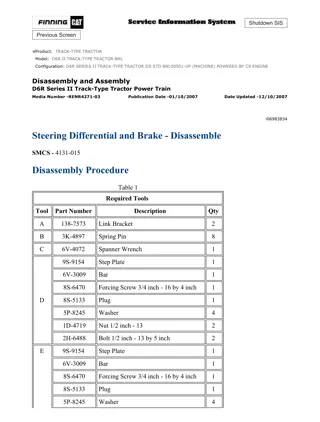
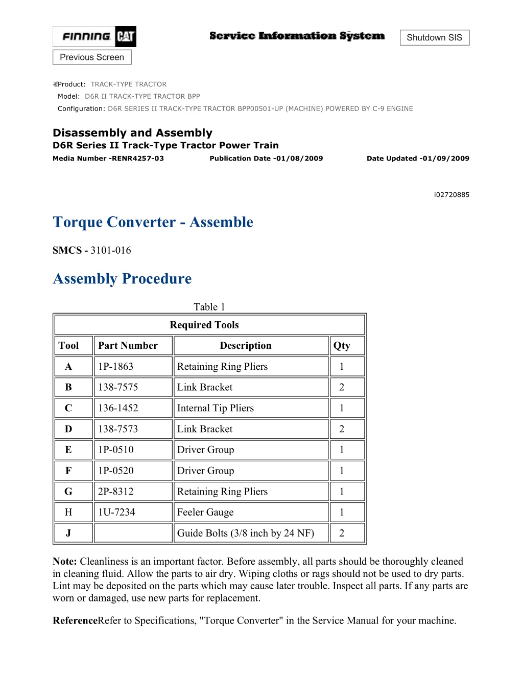
D6R SERIES II TRACK-TYPE TRACTOR BPP00501-UP (MACHINE) POWERED ... 1/13 Shutdown SIS Previous Screen Product: TRACK-TYPE TRACTOR Model: D6R II TRACK-TYPE TRACTOR BPP Configuration: D6R SERIES II TRACK-TYPE TRACTOR BPP00501-UP (MACHINE) POWERED BY C-9 ENGINE Disassembly and Assembly D6R Series II Track-Type Tractor Power Train Media Number -RENR4257-03 Publication Date -01/08/2009 Date Updated -01/09/2009 i02720885 Torque Converter - Assemble SMCS - 3101-016 Assembly Procedure Table 1 Required Tools Tool Part Number Description Qty A 1P-1863 Retaining Ring Pliers 1 B 138-7575 Link Bracket 2 C 136-1452 Internal Tip Pliers 1 D 138-7573 Link Bracket 2 E 1P-0510 Driver Group 1 F 1P-0520 Driver Group 1 G 2P-8312 Retaining Ring Pliers 1 H 1U-7234 Feeler Gauge 1 J Guide Bolts (3/8 inch by 24 NF) 2 Note: Cleanliness is an important factor. Before assembly, all parts should be thoroughly cleaned in cleaning fluid. Allow the parts to air dry. Wiping cloths or rags should not be used to dry parts. Lint may be deposited on the parts which may cause later trouble. Inspect all parts. If any parts are worn or damaged, use new parts for replacement. ReferenceRefer to Specifications, "Torque Converter" in the Service Manual for your machine. https://127.0.0.1/sisweb/sisweb/techdoc/techdoc_print_page.jsp?returnurl=/sis... 2021/2/12
D6R SERIES II TRACK-TYPE TRACTOR BPP00501-UP (MACHINE) POWERED ... 2/13 Note: In order to ensure that the torque divider is capable of efficient operation, take the measurements in Steps 1 and 2. Then, follow the procedure for assembly of the torque converter. 1. Check the clearance between the turbine wheel and the stator by performing the following steps: Illustration 1 g00837218 a. Place stator (28) on turbine wheel (35). While you hold the stator against one side of the turbine wheel, measure the clearance between the stator and the turbine wheel with Tooling (H) . b. The correct clearance between the stator and the turbine wheel is 1.76 to 1.94 mm (0.070 to 0.077 inch). Check the clearance at four different points on the turbine wheel. The maximum clearance for any measurement is 1.1 mm (0.043 inch). c. The running clearance is one half of the clearance across the diameters. The correct running clearance is 0.88 to 0.97 mm (0.035 to 0.039 inch). The maximum running clearance for any measurement is 0.38 mm (0.015 inch). 2. Check the clearance between the impeller wheel and the stator by performing the following steps: Illustration 2 g00837224 https://127.0.0.1/sisweb/sisweb/techdoc/techdoc_print_page.jsp?returnurl=/sis... 2021/2/12
D6R SERIES II TRACK-TYPE TRACTOR BPP00501-UP (MACHINE) POWERED ... 3/13 a. Use a 7 inch outside micrometer or an 8 inch outside micrometer for outside diameters in order to measure the diameter of the flange at four points on the stator. Record the minimum reading. Illustration 3 g00837227 b. Use a 7 inch inside micrometer or an 8 inch inside micrometer in order to measure the diameter of the flange at four points on impeller wheel (25). Record the maximum reading. c. The clearance across the diameters is the difference between the readings of Steps 2.b and 2.a. The correct clearance between the stator and the impeller wheel is 1.17 mm to 1.32 mm (0.046 inch to 0.052 inch). The maximum clearance for any measurement is 0.61 mm (0.024 inch). d. The running clearance is one half of the clearance across the diameters. The correct running clearance is 0.59 to 0.66 mm (0.023 to 0.026 inch). The maximum running clearance for any measurement is 0.30 mm (0.012 inch). Illustration 4 g00847454 3. Use Tooling (F) in order to install bearing (46) in housing (37) . https://127.0.0.1/sisweb/sisweb/techdoc/techdoc_print_page.jsp?returnurl=/sis... 2021/2/12
https://www.ebooklibonline.com Hello dear friend! Thank you very much for reading. Enter the link into your browser. The full manual is available for immediate download. https://www.ebooklibonline.com
D6R SERIES II TRACK-TYPE TRACTOR BPP00501-UP (MACHINE) POWERED ... 4/13 Illustration 5 g00837322 4. Place retainer (45) on the housing. Install bolts (44). Tighten the bolts to a torque of 50 7 N m (37 5 lb ft). Illustration 6 g00847545 Illustration 7 g00847883 5. Use Tooling (F) in order to install two bearings (41) in output flange (40) by performing the following steps: https://127.0.0.1/sisweb/sisweb/techdoc/techdoc_print_page.jsp?returnurl=/sis... 2021/2/12
D6R SERIES II TRACK-TYPE TRACTOR BPP00501-UP (MACHINE) POWERED ... 5/13 a. Install one bearing (41) to a 25.4 mm (1.00 inch) depth below the surface of output flange (40). See Illustration 6. b. Install one bearing (41) even with the surface of the splined end of output flange (40). See Illustration 7. c. After you install bearings (41), check the inside diameter of the bearings. The correct inside diameter after installation is 44.501 0.013 mm (1.7520 0.0005 inch). 6. If carrier (42) is separate from output flange (40), heat the carrier to a temperature of 152 14 C (305 25 F) for ten minutes. Install carrier (42) on output flange (40). Install seal ring (43) on the carrier. 7. Apply clean SAE 30W oil to seal ring (43). Pull the ends of the seal ring together. Install output flange (40) in the housing. Note: Do not damage the seals during the assembly of the components. Illustration 8 g00837307 8. Place the retaining ring on the outer groove on output flange (40). The outer groove is shown in Illustration 6. Compress the ring and install ring gear (39). In order to hold the ring gear in place, make sure that the retaining ring engages the slot in ring gear (39) . 9. Install stop pins (38) in housing (37) . https://127.0.0.1/sisweb/sisweb/techdoc/techdoc_print_page.jsp?returnurl=/sis... 2021/2/12
D6R SERIES II TRACK-TYPE TRACTOR BPP00501-UP (MACHINE) POWERED ... 6/13 Illustration 9 g00837306 10. Turn over housing (37). Place the spacer that lies under the turbine wheel on the output flange. 11. Install turbine wheel (35) on the output flange. 12. Use Tooling (G) in order to install retaining ring (36) on the output flange. Illustration 10 g00837303 13. Use Tooling (F) in order to install bearing (34) in planetary carrier (33) . https://127.0.0.1/sisweb/sisweb/techdoc/techdoc_print_page.jsp?returnurl=/sis... 2021/2/12
D6R SERIES II TRACK-TYPE TRACTOR BPP00501-UP (MACHINE) POWERED ... 7/13 Illustration 11 g00847565 14. Position planetary carrier (33) with Tooling (J) on impeller wheel (25). Use Tooling (G) in order to install the planetary carrier on the impeller wheel. Illustration 12 g00850556 15. Install dowel (X) . Illustration 13 g00837302 https://127.0.0.1/sisweb/sisweb/techdoc/techdoc_print_page.jsp?returnurl=/sis... 2021/2/12
D6R SERIES II TRACK-TYPE TRACTOR BPP00501-UP (MACHINE) POWERED ... 8/13 16. Turn over impeller wheel (25). Place retainer (32) on the impeller wheel. Install the bolts. Tighten the bolts to a torque of 50 7 N m (37 5 lb ft). Illustration 14 g00837298 17. Install pins (29) in carrier (30) . 18. Install seal ring (31) on the carrier. 19. Apply clean SAE 30W oil to seal ring (31). Pull the ends of the seal ring together. Illustration 15 g00847581 20. Position carrier (30) on impeller wheel (25) . Note: The ball should be lined up with the groove in the bearing. Note: Do not damage the seals during assembly. 21. Use Tooling (F) in order to install carrier (30) in impeller wheel (25) . https://127.0.0.1/sisweb/sisweb/techdoc/techdoc_print_page.jsp?returnurl=/sis... 2021/2/12
D6R SERIES II TRACK-TYPE TRACTOR BPP00501-UP (MACHINE) POWERED ... 9/13 Illustration 16 g00847587 Illustration 17 g00837297 22. Turn over the impeller wheel (25). Install two guide bolts (26). Place stator (28) on the impeller wheel and install bolts (27). Tighten the eight bolts to a torque of 40 5 N m (30 4 lb ft). Illustration 18 g00847598 https://127.0.0.1/sisweb/sisweb/techdoc/techdoc_print_page.jsp?returnurl=/sis... 2021/2/12
D6R SERIES II TRACK-TYPE TRACTOR BPP00501-UP (MACHINE) POWERE... 10/13 23. Turn over impeller wheel (25). The impeller wheel with the carrier weighs approximately 30 kg (65 lb). Install Tooling (D) on the impeller wheel. Attach a lifting device. Place impeller wheel (25) with the carrier on the housing. Remove Tooling (D). See Illustration 20 in order to install bolts (19). Tighten the bolts to a torque of 30 5 N m (22 4 lb ft). Illustration 19 g00837282 24. Heat bearing race (23) to a temperature of 135 C (275 F) for ten minutes. Install the bearing race on shaft (21) . 25. Install seal ring (24) on shaft (21) . 26. Heat bearing (22) to a temperature of 135 C (275 F) for ten minutes. Install the bearing on shaft (20). Apply clean SAE 30W oil to seal ring (24). Pull the ends of the seal ring together. Illustration 20 g00847851 27. Install shaft (21) and the bearing in the torque converter. Note: Do not damage the seals during assembly. 28. Use Tooling (C) in order to install retaining ring (20) . https://127.0.0.1/sisweb/sisweb/techdoc/techdoc_print_page.jsp?returnurl=/sis... 2021/2/12
D6R SERIES II TRACK-TYPE TRACTOR BPP00501-UP (MACHINE) POWERE... 11/13 29. Install O-ring seal (18) on the carrier. Apply clean SAE 30W oil to the seal. Illustration 21 g00850488 30. Install lip seal (17) in the carrier with the lip of the seal toward the bearing. Apply clean SAE 30W oil to the lip of the seal. 31. Install Tooling (B) on cover (16) and attach a hoist. The cover of the torque converter weighs approximately 70 kg (150 lb). 32. Use two guide bolts (15) in order to install cover (16) on the torque converter. Make sure that the O-ring seal stays in position when you install the cover. Illustration 22 g00850466 33. Install bolts (10). Tighten the bolts to a torque of 50 7 N m (37 5 lb ft). 34. Install yoke (13). Place sensor (12) on yoke (13). Install retainer (11) and bolt (10). Tighten bolt (10) to a torque of 115 7 N m (85 5 lb ft). https://127.0.0.1/sisweb/sisweb/techdoc/techdoc_print_page.jsp?returnurl=/sis... 2021/2/12
D6R SERIES II TRACK-TYPE TRACTOR BPP00501-UP (MACHINE) POWERE... 12/13 Illustration 23 g00533622 35. Place bearing (5) in planetary gear (6). Place one spacer (9) on each side of planetary gear (6), and place the components in the planetary carrier. Install shaft (7) . 36. Align the hole in shaft (7) with the hole in the planetary carrier. Install pin (8) even with the surface of the planetary carrier. Illustration 24 g00533624 37. Install retaining ring (3) in the inner diameter of planetary carrier (2). Position retainer (4) next to the spiral ring. https://127.0.0.1/sisweb/sisweb/techdoc/techdoc_print_page.jsp?returnurl=/sis... 2021/2/12
D6R SERIES II TRACK-TYPE TRACTOR BPP00501-UP (MACHINE) POWERE... 13/13 Illustration 25 g00495910 38. Position planetary carrier (2) in ring gear (36) and on shaft (16). Make sure that the retainer stays in place. 39. Use Tooling (A) in order to install retaining ring (1) . End By: Install the torque converter. Refer to Disassembly and Assembly, "Torque Diverter - Install". Copyright 1993 - 2021 Caterpillar Inc. Fri Feb 12 11:29:31 UTC+0800 2021 All Rights Reserved. Private Network For SIS Licensees. https://127.0.0.1/sisweb/sisweb/techdoc/techdoc_print_page.jsp?returnurl=/sis... 2021/2/12
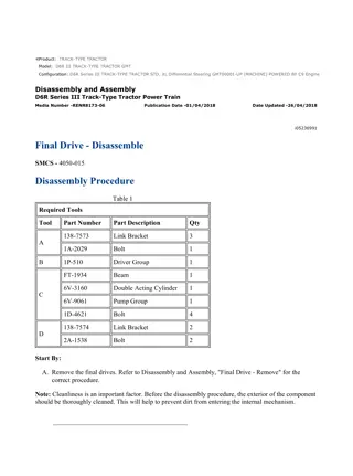
D6R SERIES II TRACK-TYPE TRACTOR BPP00501-UP (MACHINE) POWERED ... 1/9 Shutdown SIS Previous Screen Product: TRACK-TYPE TRACTOR Model: D6R II TRACK-TYPE TRACTOR BPP Configuration: D6R SERIES II TRACK-TYPE TRACTOR BPP00501-UP (MACHINE) POWERED BY C-9 ENGINE Disassembly and Assembly D6R Series II Track-Type Tractor Power Train Media Number -RENR4257-03 Publication Date -01/08/2009 Date Updated -01/09/2009 i05467849 Torque Converter - Install SMCS - 3101-012 Installation Procedure Table 1 Required Tools Tool Part Number Part Description Qty 138-7575 Link Bracket 2 A 1U-9200 Ratchet Puller 2 Illustration 1 g03454696 1. Install ring (23) and springs (22) . https://127.0.0.1/sisweb/sisweb/techdoc/techdoc_print_page.jsp?returnurl=/sis... 2021/2/12
D6R SERIES II TRACK-TYPE TRACTOR BPP00501-UP (MACHINE) POWERED ... 2/9 Illustration 2 g03454684 Typical example 2. Install gear (21) and ring (20) . Illustration 3 g00868581 3. Attach a chain around the ROPS. Attach Tooling (A) to the chains. https://127.0.0.1/sisweb/sisweb/techdoc/techdoc_print_page.jsp?returnurl=/sis... 2021/2/12
D6R SERIES II TRACK-TYPE TRACTOR BPP00501-UP (MACHINE) POWERED ... 3/9 Illustration 4 g00868586 Illustration 5 g00868584 Illustration 6 g00868582 4. Attach Tooling (A) to torque converter (19) . https://127.0.0.1/sisweb/sisweb/techdoc/techdoc_print_page.jsp?returnurl=/sis... 2021/2/12
D6R SERIES II TRACK-TYPE TRACTOR BPP00501-UP (MACHINE) POWERED ... 4/9 5. Lower torque converter (19) and remove torque converter (19) . The weight of torque converter (19) is approximately 145 kg (320 lb). 6. Install the O-ring seal (not shown) on the torque converter. 7. Connect torque converter (19) to the engine. Install bolts (18) . Illustration 7 g00868580 8. Connect tube assemblies (16) to cooler (17) . Illustration 8 g00868578 9. Connect hose assembly (15) . Install bolt (13) and bracket (14) . https://127.0.0.1/sisweb/sisweb/techdoc/techdoc_print_page.jsp?returnurl=/sis... 2021/2/12
D6R SERIES II TRACK-TYPE TRACTOR BPP00501-UP (MACHINE) POWERED ... 5/9 Illustration 9 g00868576 10. Install hose assembly (12) . Illustration 10 g00868575 11. Install hose assemblies (11) . https://127.0.0.1/sisweb/sisweb/techdoc/techdoc_print_page.jsp?returnurl=/sis... 2021/2/12
D6R SERIES II TRACK-TYPE TRACTOR BPP00501-UP (MACHINE) POWERED ... 6/9 Illustration 11 g00868574 12. Install bottom guard (10) . Install bolts (9) . Illustration 12 g00868573 13. Connect hose (8) and tighten hose clamp (7) . https://127.0.0.1/sisweb/sisweb/techdoc/techdoc_print_page.jsp?returnurl=/sis... 2021/2/12
D6R SERIES II TRACK-TYPE TRACTOR BPP00501-UP (MACHINE) POWERED ... 7/9 Illustration 13 g00868572 14. Connect harness assembly (6) . Illustration 14 g00868571 15. Connect harness assembly (5) . https://127.0.0.1/sisweb/sisweb/techdoc/techdoc_print_page.jsp?returnurl=/sis... 2021/2/12
D6R SERIES II TRACK-TYPE TRACTOR BPP00501-UP (MACHINE) POWERED ... 8/9 Illustration 15 g00868570 16. Install four bolts (4) . Illustration 16 g00868568 17. Connect hose assembly (3) to the flywheel housing. Illustration 17 g00868567 18. Install bracket (2) and install bolt (1) . https://127.0.0.1/sisweb/sisweb/techdoc/techdoc_print_page.jsp?returnurl=/sis... 2021/2/12
D6R SERIES II TRACK-TYPE TRACTOR BPP00501-UP (MACHINE) POWERED ... 9/9 19. Check the level of the power train oil. Refer to Operation and Maintenance Manual, SEBU7299, "Transmission System Oil Level - Check" for the correct procedure. 20. Install the floorplate. , End By: a. Install the drive shaft. Refer to Disassembly and Assembly, "Drive Shaft - Remove and Install". b. Install the bottom guards. Refer to Disassembly and AssemblyRENR4261, "Bottom Guard - Install". Copyright 1993 - 2021 Caterpillar Inc. Fri Feb 12 11:30:31 UTC+0800 2021 All Rights Reserved. Private Network For SIS Licensees. https://127.0.0.1/sisweb/sisweb/techdoc/techdoc_print_page.jsp?returnurl=/sis... 2021/2/12
D6R SERIES II TRACK-TYPE TRACTOR BPP00501-UP (MACHINE) POWERED ... 1/6 Shutdown SIS Previous Screen Product: TRACK-TYPE TRACTOR Model: D6R II TRACK-TYPE TRACTOR BPP Configuration: D6R SERIES II TRACK-TYPE TRACTOR BPP00501-UP (MACHINE) POWERED BY C-9 ENGINE Disassembly and Assembly D6R Series II Track-Type Tractor Power Train Media Number -RENR4257-03 Publication Date -01/08/2009 Date Updated -01/09/2009 i01689260 Transmission and Bevel Gears - Remove SMCS - 3010-011; 3150-011 Removal Procedure Table 1 Required Tools Tool Part Number Part Description Qty FT-1897 Bracket 1 A 138-7575 Link Bracket 2 B Forcing Bolt (1/2 by 13 NC by 3) 2 C 180-3033 Stand 1 D 8S-9906 Ratchet Puller 1 E 138-7573 Link Bracket 2 F 138-7574 Link Bracket 2 Start By: A. Remove the drive shaft. Refer to Disassembly and Assembly, "Drive Shaft - Remove and Install". B. Remove the axles. Refer to Disassembly and Assembly, "Axle - Remove and Install". Note: Cleanliness is an important factor. Before the disassembly procedure, the exterior of the component should be thoroughly cleaned. This will help to prevent dirt from entering the internal mechanism. NOTICE https://127.0.0.1/sisweb/sisweb/techdoc/techdoc_print_page.jsp?returnurl=/sis... 2021/2/12
D6R SERIES II TRACK-TYPE TRACTOR BPP00501-UP (MACHINE) POWERED ... 2/6 Care must be taken to ensure that fluids are contained during performance of inspection, maintenance, testing, adjusting and repair of the product. Be prepared to collect the fluid with suitable containers before opening any compartment or disassembling any component containing fluids. Refer to Special Publication, NENG2500, "Caterpillar Tools and Shop Products Guide" for tools and supplies suitable to collect and contain fluids on Caterpillar products. Dispose of all fluids according to local regulations and mandates. Note: Put identification marks on all lines, on all hoses, on all wires, and on all tubes for installation purposes. Plug all lines, hoses, and tubes. This helps to prevent fluid loss and this helps to keep contaminants from entering the system. 1. Lower the ripper to the ground. Remove the ripper shanks or invert the ripper shanks. 2. Drain the power train oil into a suitable container for storage or disposal. The capacity of the power train oil system is 148 L (38.5 US gal). 3. Attach a suitable lifting device to the ripper assembly. Remove the cylinder pin and lower the ripper assembly to the ground. Illustration 1 g00869668 4. Remove bolts (1) and bolts (2). Remove guard assembly (3) . Note: Do not disconnect the ripper lines. https://127.0.0.1/sisweb/sisweb/techdoc/techdoc_print_page.jsp?returnurl=/sis... 2021/2/12
D6R SERIES II TRACK-TYPE TRACTOR BPP00501-UP (MACHINE) POWERED ... 3/6 Illustration 2 g00869704 Illustration 3 g00869817 5. Remove bolts (4) and remove guard (5) . 6. Remove bolts (6) and cover (7). Install Tooling (A). Remove bolts (8) and cover (9). Attach a suitable lifting device to Tooling (A) . Illustration 4 g00869763 https://127.0.0.1/sisweb/sisweb/techdoc/techdoc_print_page.jsp?returnurl=/sis... 2021/2/12
D6R SERIES II TRACK-TYPE TRACTOR BPP00501-UP (MACHINE) POWERED ... 4/6 7. Remove cover (10). Disconnect tube assembly (11) . Illustration 5 g00869820 8. Disconnect harness assembly (12). Remove bolts (13) . Illustration 6 g00869824 9. Attach a suitable lifting device to Tooling (A). Apply a small amount of lifting pressure to Tooling (A). Install Tooling (B) and separate the transmission and bevel gears from the case. https://127.0.0.1/sisweb/sisweb/techdoc/techdoc_print_page.jsp?returnurl=/sis... 2021/2/12
Suggest: If the above button click is invalid. Please download this document first, and then click the above link to download the complete manual. Thank you so much for reading
D6R SERIES II TRACK-TYPE TRACTOR BPP00501-UP (MACHINE) POWERED ... 5/6 Illustration 7 g00869829 10. Place the transmission and bevel gears on Tooling (C). Remove Tooling (A) . Illustration 8 g00869833 11. Remove the pin from the left hand link (14). Attach Tooling (D) and lift the link out of the way. Illustration 9 g00869900 https://127.0.0.1/sisweb/sisweb/techdoc/techdoc_print_page.jsp?returnurl=/sis... 2021/2/12
D6R SERIES II TRACK-TYPE TRACTOR BPP00501-UP (MACHINE) POWERED ... 6/6 12. Install bolts (6) and cover (7) and attach Tooling (E). Attach a suitable lifting device to Tooling (E). Lift the transmission and bevel gears on the rails. Allow the transmission to rest on the ripper. Illustration 10 g00869911 Illustration 11 g00869923 13. Attach Tooling (F) to the transmission and bevel gears (15). Remove the transmission and bevel gears. Use a pry bar to balance the transmission and bevel gears (15). The weight of transmission and bevel gears is approximately 816 kg (1800 lb). Copyright 1993 - 2021 Caterpillar Inc. Fri Feb 12 11:31:30 UTC+0800 2021 All Rights Reserved. Private Network For SIS Licensees. https://127.0.0.1/sisweb/sisweb/techdoc/techdoc_print_page.jsp?returnurl=/sis... 2021/2/12
https://www.ebooklibonline.com Hello dear friend! Thank you very much for reading. Enter the link into your browser. The full manual is available for immediate download. https://www.ebooklibonline.com


