Caterpillar Cat CS-431C VIbratory Compactor (Prefix 3WZ) Service Repair Manual Instant Download (3WZ00001 and up)
Please open the website below to get the complete manualnn// n

Download Presentation

Please find below an Image/Link to download the presentation.
The content on the website is provided AS IS for your information and personal use only. It may not be sold, licensed, or shared on other websites without obtaining consent from the author. Download presentation by click this link. If you encounter any issues during the download, it is possible that the publisher has removed the file from their server.
E N D
Presentation Transcript
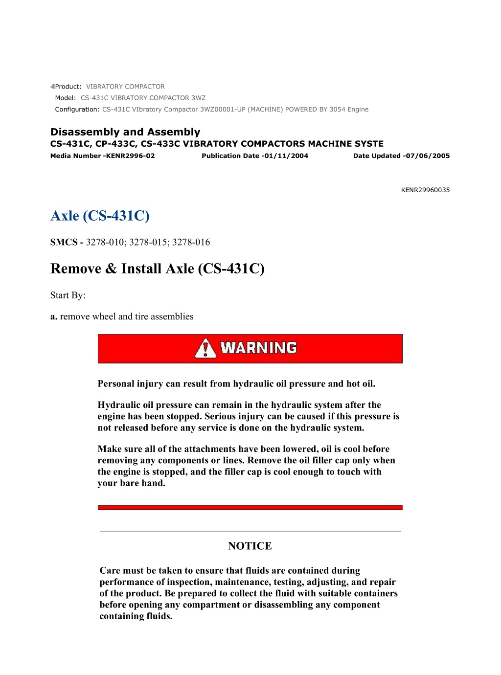
CS-431C VIbratory Compactor 3WZ00001-UP (MACHINE) POWERED BY 3054 En... 1/23 Product: VIBRATORY COMPACTOR Model: CS-431C VIBRATORY COMPACTOR 3WZ Configuration: CS-431C VIbratory Compactor 3WZ00001-UP (MACHINE) POWERED BY 3054 Engine Disassembly and Assembly CS-431C, CP-433C, CS-433C VIBRATORY COMPACTORS MACHINE SYSTE Media Number -KENR2996-02 Publication Date -01/11/2004 Date Updated -07/06/2005 KENR29960035 Axle (CS-431C) SMCS - 3278-010; 3278-015; 3278-016 Remove & Install Axle (CS-431C) Start By: a. remove wheel and tire assemblies Personal injury can result from hydraulic oil pressure and hot oil. Hydraulic oil pressure can remain in the hydraulic system after the engine has been stopped. Serious injury can be caused if this pressure is not released before any service is done on the hydraulic system. Make sure all of the attachments have been lowered, oil is cool before removing any components or lines. Remove the oil filler cap only when the engine is stopped, and the filler cap is cool enough to touch with your bare hand. NOTICE Care must be taken to ensure that fluids are contained during performance of inspection, maintenance, testing, adjusting, and repair of the product. Be prepared to collect the fluid with suitable containers before opening any compartment or disassembling any component containing fluids. https://127.0.0.1/sisweb/sisweb/techdoc/techdoc_print_page.jsp?returnurl=/sis... 2021/6/27
CS-431C VIbratory Compactor 3WZ00001-UP (MACHINE) POWERED BY 3054 En... 2/23 Refer to Special Publication, NENG2500, "Caterpillar Tools and Shop Products Guide" for tools and supplies suitable to collect and contain fluids on Caterpillar products. Dispose of all fluids according to local regulations and mandates. NOTE: Identify all hydraulic lines as they are removed for reinstallation purposes. Cap and plug all lines and fittings to prevent any contaminants from entering the system. 1. Drain the hydraulic oil from the hydraulic oil tank into a suitable container. The capacity of the hydraulic oil tank is 72 liters (19 U.S. gal). 2. Drain the oil from the differential into a suitable container. The capacity of the differential is approximately 10.8 liters (2.81 U.S. gal). 3. Open the engine access door on the right side of the machine. 3. Disconnect hose assembly (1) from the axle propel motor. Cap and plug immediately. 4. Disconnect hose assemblies (2) and (3) from axle propel motor (4). Cap and plug immediately. 5. Disconnect hose assembly (5) from both sides of the axle. Cap and plug immediately. 6. Remove the two bolts that fasten bracket (6) to the axle. Move the bracket and hose assemblies out of the way. https://127.0.0.1/sisweb/sisweb/techdoc/techdoc_print_page.jsp?returnurl=/sis... 2021/6/27
CS-431C VIbratory Compactor 3WZ00001-UP (MACHINE) POWERED BY 3054 En... 3/23 NOTE: The axle, reduction case assembly and axle propel motor are removed as a unit in the following steps. 7. Attach a hoist and lifting straps to both sides of axle (8). 8. Remove four bolts (7), the washers and nuts that hold the axle (8) to the frame of the machine. 9. Lower the axle to the ground, and remove axle (8) from under the machine. Weight of the axle is 800 kg (1760 lb). NOTE: For installation of the axle, reverse the removal steps. NOTE: After the axle has been installed, fill the hydraulic oil tank and differential with oil to the correct level. See the Operation & Maintenance Manual Form No. KEBU6859, for the correct filling procedures. End By: a. install wheel and tire assemblies Disassemble Axle (CS-431C) Start By: a. remove axle (CS-431C) https://127.0.0.1/sisweb/sisweb/techdoc/techdoc_print_page.jsp?returnurl=/sis... 2021/6/27
https://www.ebooklibonline.com Hello dear friend! Thank you very much for reading. Enter the link into your browser. The full manual is available for immediate download. https://www.ebooklibonline.com
CS-431C VIbratory Compactor 3WZ00001-UP (MACHINE) POWERED BY 3054 En... 4/23 1. Remove the two bolts, and remove the axle propel motor from the axle. 2. Put an alignment mark across the reduction case and the carrier for assembly purposes. 3. Remove the drain plug from the rear reduction case assembly, and drain the oil. The capacity of the rear reduction case assembly is .95 liters (.250 U.S. gal). 4. Remove two dowels (1) from the reduction case with a hammer and a punch. 5. Remove 15 nuts and bolts (3), and remove cover (2). 6. Remove snap ring (4) from the cover. https://127.0.0.1/sisweb/sisweb/techdoc/techdoc_print_page.jsp?returnurl=/sis... 2021/6/27
CS-431C VIbratory Compactor 3WZ00001-UP (MACHINE) POWERED BY 3054 En... 5/23 7. Remove the four bolts, and remove input shaft cap (5) from gear case (6). 8. Remove nut (7) and the washer. Using a soft faced hammer, remove reduction drive gear (8) and input gear (9). 9. Remove bearings (10) from input gear (9). https://127.0.0.1/sisweb/sisweb/techdoc/techdoc_print_page.jsp?returnurl=/sis... 2021/6/27
CS-431C VIbratory Compactor 3WZ00001-UP (MACHINE) POWERED BY 3054 En... 6/23 10. Remove eight nuts (12), and remove gear case (6) and bearing cone (11) from carrier (14). If necessary, remove the bearing cup from the gear case. 11. Remove spacer (18), bearing cage (23), pinion shaft (21) and shims (16) from carrier (14). 12. Remove retaining ring (19), bearing (20) and bearing cone (17) from pinion shaft (21). 13. Remove bearing cup (22) from bearing cage (23). 14. Attach Tooling (A) and a hoist to two of the studs on carrier (14). Remove 12 bolts (13), and remove carrier (14) and the differential from axle housing (15). The weight of the carrier and differential as a unit is 65 kg (143 lb). 15. Position the differential and carrier on Tooling (B) with the bevel gear up. NOTE: Put identification marks on bearing caps (27) and the carrier. Make sure they are installed in their original locations during assembly. 16. Remove two lock pins (24). Loosen four bolts (25) that hold two bearing caps (27), then loosen two bearing adjuster nuts (26) approximately 1/2 turn. Remove four bolts (25) and bearing caps (27). https://127.0.0.1/sisweb/sisweb/techdoc/techdoc_print_page.jsp?returnurl=/sis... 2021/6/27
CS-431C VIbratory Compactor 3WZ00001-UP (MACHINE) POWERED BY 3054 En... 7/23 17. Put a bar through the differential as shown. Fasten a hoist to the bar, and remove the differential from the carrier. The weight of the differential is 35 kg (77 lb). NOTE: Put identification marks on bearing cups (28), and make sure they are installed with their respective bearing cones during assembly. 18. Remove two bearing adjuster nuts (26) and two bearing cups (28) from the differential. 19. Install Tooling (B) and remove two bearing cones (29) from the differential. 20. Remove two bolts (30), opposite each other, and install Tooling (C) as shown. Remove the remaining bolts (30). 21. Put identification marks on upper case (32) and lower case (31) for assembly purposes. https://127.0.0.1/sisweb/sisweb/techdoc/techdoc_print_page.jsp?returnurl=/sis... 2021/6/27
CS-431C VIbratory Compactor 3WZ00001-UP (MACHINE) POWERED BY 3054 En... 8/23 Upper case (32) holds a spring under compression. To prevent possible personal injury, remove nuts (33) slowly to release the spring pressure. 22. Slowly and evenly remove two nuts (33) [part of Tooling (D)]. and remove upper case (32) and differential assembly (34) from the lower case. NOTE: The differential assembly is the same on one side of spider (41) as it is on the other side (symmetrical). Only one side of the assembly is shown. 23. To dissemble the differential assembly, remove side gear (36), retainer (35), spring (37), driven clutch (38), holdout ring (39) and center cam (40) from spider (41). 24. Remove 12 bolts (42), and separate bevel gear (43) from lower case (31). Assemble Axle (CS-431C) https://127.0.0.1/sisweb/sisweb/techdoc/techdoc_print_page.jsp?returnurl=/sis... 2021/6/27
CS-431C VIbratory Compactor 3WZ00001-UP (MACHINE) POWERED BY 3054 En... 9/23 NOTE: Inspect all parts for wear or damage, and make replacements if needed. 1. Install bevel gear (43) on lower case (31), and install 12 bolts (42). Tighten the bolts to a torque of 135 15 N m (100 11 lb ft). https://127.0.0.1/sisweb/sisweb/techdoc/techdoc_print_page.jsp?returnurl=/sis... 2021/6/27
CS-431C VIbratory Compactor 3WZ00001-UP (MACHINE) POWERED BY 3054 ... 10/23 2. Install center cam (40) in spider (41). 3. Install holdout rings (39), driven clutches (38), springs (37), retainers (35) and side gear (36) on each side of spider (41). 4. Position the differential assembly in lower case (31). NOTE: Make sure the identification marks on the upper and lower cases are in alignment. 5. Put upper case (32) in position on differential assembly (34), and install Tooling (D). 6. Use Tooling (D) to compress the springs in the differential assembly. 7. Install bolts (30) that hold lower case (31) and upper case (32) together. Tighten the bolts to a torque of 55 7 N m (41 5 lb ft). 8. Remove Tooling (D), and install the remaining two bolts. Tighten the bolts to a torque of 55 7 N m (41 5 lb ft). 9. Heat bearing cones (29) to a maximum temperature of 135 C (275 F). Install the bearing cones on each end of the differential. Make sure the bearing cones are against (seated) the shoulders of the differential cases. https://127.0.0.1/sisweb/sisweb/techdoc/techdoc_print_page.jsp?returnurl=/sis... 2021/6/27
CS-431C VIbratory Compactor 3WZ00001-UP (MACHINE) POWERED BY 3054 ... 11/23 10. Use the following procedure to adjust the thickness of shims (16) for obtaining the correct pinion cage (depth of pinion shaft). NOTE: Use this procedure if a new pinion shaft and bevel gear set is installed, or if the depth of the pinion shaft must be adjusted. a. Use a micrometer to measure the thickness of shims (16) that were originally removed from under bearing cage (23). Record the measurement for later use. b. Look for the pinion cone ("PC") variation number, location X, on the old pinion shaft that is being replaced. Record the number for later use. If the ("PC") variation number cannot be located, assemble the pinion shaft with a shim pack thickness obtained in step a. NOTE: The ("PC") variation number can be either 100ths of a millimeter or 1,000ths of an inch. PC+.03, PC-.03 equals +.03 or -.03 millimeters respectively. PC+3, PC-3 equals +.003 or -.003 inches respectively. https://127.0.0.1/sisweb/sisweb/techdoc/techdoc_print_page.jsp?returnurl=/sis... 2021/6/27
CS-431C VIbratory Compactor 3WZ00001-UP (MACHINE) POWERED BY 3054 ... 12/23 NOTE: The value calculated in step c or d is the thickness of the standard shim pack, without a variation. c. If the ("PC") variation number on the old pinion shaft is a plus (+), subtract the number from the original shim pack thickness that was measured in step a. d. If the ("PC") variation number on the old pinion shaft is a minus (-), add the number from the original shim pack thickness that was measured in step a. e. Look for the pinion cone ("PC") variation number, location X, on the new pinion shaft that is being installed. Record the number for later use. NOTE: The value calculated in step e or f is the thickness of the new shim pack that will be installed. f. If the ("PC") variation number on the new pinion shaft is a plus (+), add the number from the standard shim pack thickness that was measured in steps c or d. g. If the ("PC") variation number on the new pinion shaft is a minus (-), subtract the number from the standard shim pack thickness that was measured in steps c or d. https://127.0.0.1/sisweb/sisweb/techdoc/techdoc_print_page.jsp?returnurl=/sis... 2021/6/27
CS-431C VIbratory Compactor 3WZ00001-UP (MACHINE) POWERED BY 3054 ... 13/23 https://127.0.0.1/sisweb/sisweb/techdoc/techdoc_print_page.jsp?returnurl=/sis... 2021/6/27
CS-431C VIbratory Compactor 3WZ00001-UP (MACHINE) POWERED BY 3054 ... 14/23 11. Use the following procedure to adjust the pinion bearing preload. a. Install bearing (20) on pinion shaft (21), and install retaining ring (19). Install bearing cone (17) on the pinion shaft. b. Install bearing cup (22) in bearing cage (23). c. Install bearing cup (44) in gear case (6). d. Install pinion shaft (21), bearing cage (23), spacer (18) and gear case (6) on carrier (14). Install eight washers and nuts (12). e. Install bearing cone (11), gear (8), the washer and nut (7) on the pinion shaft. Tighten nut (7) to a torque of 407 to 542 N m (300 to 400 lb ft). f. Attach a socket and torque wrench on nut (7). Rotate the pinion shaft and read the value indicated on the torque wrench. g. The torque needed to rotate the pinion shaft must be 1.70 to 2.83 N m (15 to 25 lb ft). If the rolling torque (preload) required to rotate the pinion shaft is not correct, spacer (18) must be changed. To increase the rolling torque, install a thinner spacer. To decrease the rolling torque (preload), install a thicker spacer. h. When the rolling torque (preload is correct, remove the gear case, bearing cage and pinion shaft from the carrier. https://127.0.0.1/sisweb/sisweb/techdoc/techdoc_print_page.jsp?returnurl=/sis... 2021/6/27
CS-431C VIbratory Compactor 3WZ00001-UP (MACHINE) POWERED BY 3054 ... 15/23 12. Put clean oil on the two bearing cones. Install bearing cups (28) over the bearing cones to prevent damage during assembly. 13. Put a bar through the differential as shown, and fasten a hoist to the bar. Put the differential in position in carrier (14). 14. Install two bearing caps (27) and four bolts (25) finger tight. Install two bearing adjuster nuts (26). NOTE: Bearing adjuster nuts (26) must turn freely after they are installed. 15. Tighten bolts (25) by hand four to six turns, then tighten the bolts to a torque of 149 to 197 N m (110 to 145 lb ft). 16. Tighten both bearing adjuster nuts (26) evenly until there is a small amount of backlash and zero preload on the differential bearings. https://127.0.0.1/sisweb/sisweb/techdoc/techdoc_print_page.jsp?returnurl=/sis... 2021/6/27
CS-431C VIbratory Compactor 3WZ00001-UP (MACHINE) POWERED BY 3054 ... 16/23 NOTE: The correct thickness of shims (16) was determined in step 10. NOTE: The correct thickness of spacer (18) was determined in step 11. 17. Put a 3.2 mm (.125 in) continuous bead of 8T-9022 General Purpose Adhesive Sealant on the face of carrier (14) at the location for bearing cage (23). The sealant should go around the inner edge of all fastener holes to ensure complete sealing. Install pinion shaft (21), shims (16), bearing cage (23) and spacer (18). 18. Put a 3.2 mm (.125 in) continuous bead of 8T-9022 General Purpose Adhesive Sealant on the face of gear case (6) at the location it mounts to bearing cage (23). Install gear case (6) on the bearing cage, and install eight washers and nuts (12). Tighten the nuts to a torque of 48 to 68 N m (35 to 50 lb ft). 19. Install bearing cone (11), reduction drive gear (8), the washer and nut (7) on the pinion shaft. Tighten nut (7) to a torque of 407 to 542 N m (300 to 400 lb ft). https://127.0.0.1/sisweb/sisweb/techdoc/techdoc_print_page.jsp?returnurl=/sis... 2021/6/27
CS-431C VIbratory Compactor 3WZ00001-UP (MACHINE) POWERED BY 3054 ... 17/23 20. Use the following procedure to adjust the differential bearing preload. a. Attach Tooling (E) on the mounting flange of the carrier as shown. Position the dial indicator against the back surface of bevel gear (43). b. Loosen bearing adjuster nut (26) that is opposite bevel gear (43) so that a small amount of end play shows on the dial indicator. https://127.0.0.1/sisweb/sisweb/techdoc/techdoc_print_page.jsp?returnurl=/sis... 2021/6/27
CS-431C VIbratory Compactor 3WZ00001-UP (MACHINE) POWERED BY 3054 ... 18/23 c. Use either of the above methods to move the differential and bevel gear to the left and right with pry bars as shown. Make note of the end play. The pry bar must not touch the differential bearings. d. Tighten the same bearing adjuster nut (26) so that no end play shows on the dial indicator. Move the differential and bevel gear to the left and right as needed, repeating step c. e. Tighten both bearing adjuster nuts one notch from the zero end play measured in step d. https://127.0.0.1/sisweb/sisweb/techdoc/techdoc_print_page.jsp?returnurl=/sis... 2021/6/27
CS-431C VIbratory Compactor 3WZ00001-UP (MACHINE) POWERED BY 3054 ... 19/23 21. Use the following procedure to check runout of the bevel gear. a. Attach Tooling (E) on the mounting flange of the carrier as shown. Position the dial indicator against the back surface of bevel gear (43). b. Rotate the differential and bevel gear while reading the dial indicator. The runout of the bevel gear must not exceed 0.20 mm (.008 in). c. If the runout of the bevel gear exceed 0.20 mm (.008 in), the differential and bevel gear must be removed from the carrier. Check the differential parts including the carrier for the problem that causes excess runout, and repair or replace the necessary parts. d. After the parts are repaired or replaced, install the differential and bevel gear into the carrier. e. Repeat step 20 to adjust the differential bearing preload. 22. Attach Tooling (E) on the mounting flange of the carrier. Position the dial indicator against the tooth surface of the bevel gear as shown. 23. While holding the pinion shaft in position, Rotate the differential and bevel gear a small amount in both directions against the teeth of the pinion shaft. The backlash must be 0.20 to 0.46 mm (.008 to .018 in). NOTE: The differential bearing preload established in step 20 will be kept only if one bearing adjuster nut is loosened and the other bearing adjuster nut is tightened the same amount. https://127.0.0.1/sisweb/sisweb/techdoc/techdoc_print_page.jsp?returnurl=/sis... 2021/6/27
CS-431C VIbratory Compactor 3WZ00001-UP (MACHINE) POWERED BY 3054 ... 20/23 24. If the backlash is too much, loosen the bearing adjuster nut opposite the bevel gear, and tighten the other bearing adjuster nut the same amount. 25. If the backlash is not enough, loosen the bearing adjuster nut to adjacent the bevel gear, and tighten the other bearing adjuster nut the same amount. 26. After the gear clearance (backlash) and the differential bearing preload adjustments have been made, check the tooth contact setting between the bevel gear and the pinion shaft using the following procedure. a. Put a small amount of marking compound (Prussian blue) on the bevel gear teeth. Turn the pinion shaft in both directions, and check the marks made on the bevel gear teeth. b. With no load, the correct tooth contact setting will be as shown. The correct area of tooth contact is located equally on both sides and starts near the toe of the gear and goes 30% to 50% up the length of the tooth. With this setting, when a load is put on the gear, the load will be over the correct area of the teeth. https://127.0.0.1/sisweb/sisweb/techdoc/techdoc_print_page.jsp?returnurl=/sis... 2021/6/27
CS-431C VIbratory Compactor 3WZ00001-UP (MACHINE) POWERED BY 3054 ... 21/23 c. If the pinion shaft is too far away from the bevel gear, short toe contact will be the result as shown. The teeth of the pinion shaft will be in contact with the toe ends of the convex faces (part that makes a curve toward the outside), and the top edge of the heel end of the concave faces (part that makes a curve toward the inside). To correct this, remove shims (18) from between the bearing cage and the carrier. After this is done, check the gear clearance (backlash) and tooth contact again. d. If the pinion shaft is too near to the center of the bevel gear, short heel contact will be the result as shown. The teeth of the pinion shaft will be in contact with the toe ends of the concave faces (part that makes a curve toward the inside), and the heel ends of the convex faces (part that makes a curve toward the outside). To correct this, add shims (18) between the bearing cage and the carrier. After this is done, check the gear clearance (backlash) and tooth contact again. NOTE: Several adjustments of shim thickness may be needed before correct tooth contact and gear clearance (backlash) is made. Always remember that a change to the gear clearance (backlash) will https://127.0.0.1/sisweb/sisweb/techdoc/techdoc_print_page.jsp?returnurl=/sis... 2021/6/27
Suggest: For more complete manuals. Please go to the home page. https://www.ebooklibonline.com If the above button click is invalid. Please download this document first, and then click the above link to download the complete manual. Thank you so much for reading
CS-431C VIbratory Compactor 3WZ00001-UP (MACHINE) POWERED BY 3054 ... 22/23 also change the tooth contact. Therefore, be sure gear clearance (backlash) is in correct adjustment before tooth contact is checked. e. After gear clearance (backlash) and tooth contact are correct, remove the extra marking compound (Prussian blue) from the bevel gear and pinion shaft. 27. Install two lock pins (24) that hold the bearing adjuster nuts in position. 28. Install bearings (10) on input gear (9). 29. Put a 3.2 mm (.125 in) continuous bead of 4C-9612 Silicone Sealant on the mounting surface of axle housing (15) where the carrier fastens. Make sure the sealant is applied around the bolt holes. 30. Attach Tooling (A) and a hoist to gear case (6). Position carrier (14) on the axle housing, and install 12 bolts (13). Tighten the bolts to a torque of 81 to 102 N m (60 to 75 lb ft). 31. Remove nut (7), the washer and reduction drive gear (8). Install reduction drive gear (8) and input gear (9) at the same time. Install the washer and nut (7) on the pinion shaft. Tighten nut (7) to a torque of 407 to 542 N m (300 to 400 lb ft). https://127.0.0.1/sisweb/sisweb/techdoc/techdoc_print_page.jsp?returnurl=/sis... 2021/6/27
CS-431C VIbratory Compactor 3WZ00001-UP (MACHINE) POWERED BY 3054 ... 23/23 32. Put a 3.2 mm (.125 in) continuous bead of 8T-9022 General Purpose Adhesive Sealant on the mounting surface of gear case (6) where input shaft cap (5) fastens. Position the input shaft cap on the gear case, and install the four bolts. 33. Install snap ring (4) in cover (2). 34. Put a 3.2 mm (.125 in) continuous bead of 8T-9022 General Purpose Adhesive Sealant on the mounting surface of gear case (6) where cover (2) fastens. Position the cover on the gear case, and install two dowels (1) and 15 nuts and bolts (3). 35. Position the axle propel motor on the axle, and install the two bolts. 36. Fill the rear reduction case assembly with oil to the correct level. See the Operation & Maintenance Manual Form No. KEBU6859, for the correct filling procedure. End By: a. install axle (CS-431C) https://127.0.0.1/sisweb/sisweb/techdoc/techdoc_print_page.jsp?returnurl=/sis... 2021/6/27
https://www.ebooklibonline.com Hello dear friend! Thank you very much for reading. Enter the link into your browser. The full manual is available for immediate download. https://www.ebooklibonline.com
 POWERED BY")
 POWERED BY")
 POWERED BY")

 POWERED BY")
 POWERED BY")
 POWERED BY")
 POWERED BY")
 POWERED BY")
 POWERED BY")
 POWERED BY")
 POWERED BY")
 POWERED BY")
 POWERED BY")
 POWERED BY")
 POWERED BY")
 POWERED BY")
 POWERED BY")
 POWERED BY")
 POWERED BY")
 POWERED BY")
 POWERED BY")

 POWERED BY")
 POWERED BY")