Caterpillar Cat CB36B Compactor (Prefix M36) Service Repair Manual Instant Download (M3600001 and up)
Please open the website below to get the complete manualnn//
Download Presentation

Please find below an Image/Link to download the presentation.
The content on the website is provided AS IS for your information and personal use only. It may not be sold, licensed, or shared on other websites without obtaining consent from the author. Download presentation by click this link. If you encounter any issues during the download, it is possible that the publisher has removed the file from their server.
E N D
Presentation Transcript
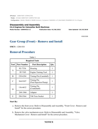
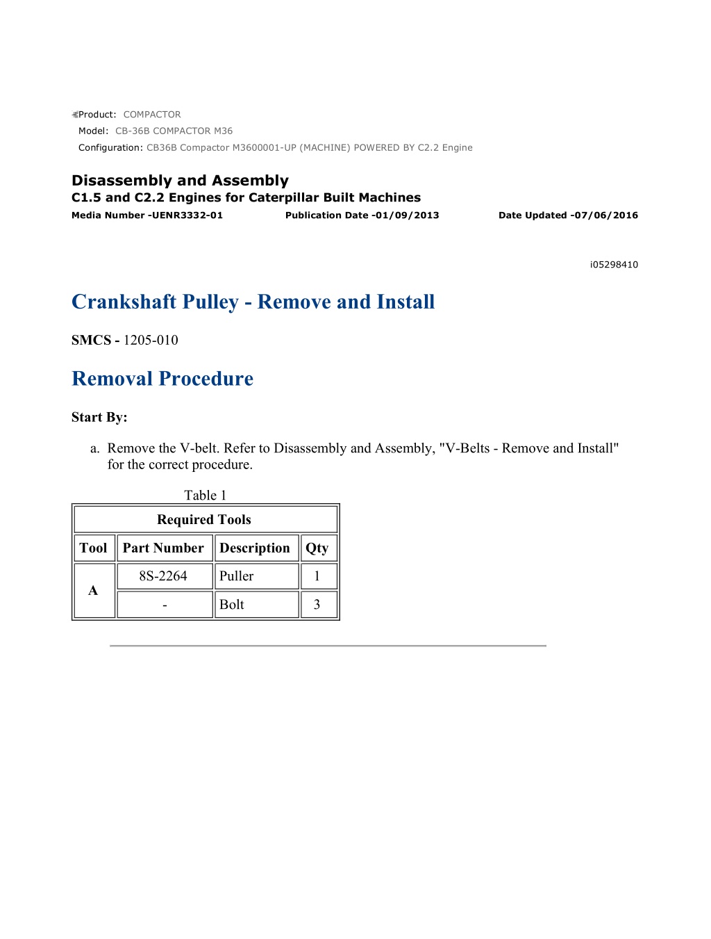
CB36B Compactor M3600001-UP (MACHINE) POWERED BY C2.2 Engine(KEBP6... 1/4 Product: COMPACTOR Model: CB-36B COMPACTOR M36 Configuration: CB36B Compactor M3600001-UP (MACHINE) POWERED BY C2.2 Engine Disassembly and Assembly C1.5 and C2.2 Engines for Caterpillar Built Machines Media Number -UENR3332-01 Publication Date -01/09/2013 Date Updated -07/06/2016 i05298410 Crankshaft Pulley - Remove and Install SMCS - 1205-010 Removal Procedure Start By: a. Remove the V-belt. Refer to Disassembly and Assembly, "V-Belts - Remove and Install" for the correct procedure. Table 1 Required Tools Tool Part Number Description Qty 8S-2264 Puller 1 A - Bolt 3 https://127.0.0.1/sisweb/sisweb/techdoc/techdoc_print_page.jsp?returnurl=/sis... 2023/3/20
CB36B Compactor M3600001-UP (MACHINE) POWERED BY C2.2 Engine(KEBP6... 2/4 Illustration 1 g03338644 https://127.0.0.1/sisweb/sisweb/techdoc/techdoc_print_page.jsp?returnurl=/sis... 2023/3/20
CB36B Compactor M3600001-UP (MACHINE) POWERED BY C2.2 Engine(KEBP6... 3/4 Illustration 2 g03338645 1. Loosen nut (3). Note: Do not remove the nut at this time. 2. Install Tooling (A) to crankshaft pulley (2). Use Tooling (A) in order to remove crankshaft pulley (2) from crankshaft (4). 3. Remove Tooling (A). 4. Remove nut (3). 5. Remove pulley (2) from crankshaft (4). 6. Remove woodruff key (1) from crankshaft (4). Installation Procedure 1. Ensure that the following components are clean and free from damage: the taper of the crankshaft, the woodruff key and the bore of the crankshaft pulley. Replace any components that are damaged. Ensure that the taper of the crankshaft and the bore of the crankshaft pulley are clean and dry before assembly. 2. Inspect the crankshaft front seal for leaks, if necessary replace the crankshaft front seal. Refer to Disassembly and Assembly, "Crankshaft Front Seal - Remove and Install" for the correct procedure. https://127.0.0.1/sisweb/sisweb/techdoc/techdoc_print_page.jsp?returnurl=/sis... 2023/3/20
https://www.ebooklibonline.com Hello dear friend! Thank you very much for reading. Enter the link into your browser. The full manual is available for immediate download. https://www.ebooklibonline.com
CB36B Compactor M3600001-UP (MACHINE) POWERED BY C2.2 Engine(KEBP6... 4/4 Illustration 3 g03338644 3. Install woodruff key (1) to crankshaft (4). 4. Install crankshaft pulley (2) to crankshaft (4). 5. Lubricate nut (3) with clean engine oil and install the nut. For C1.5 and C2.2, engines, tighten nut (5) to a torque of 333 N m (246 lb ft). End By: a. Install the V-belt. Refer to Disassembly and Assembly, "V-Belts - Remove and Install" for the correct procedure. b. Install the belt to the ARD (air Pump). Refer to Disassembly and Assembly, "Belts (ARD Air Pump) - Remove and Install" for the correct procedure. https://127.0.0.1/sisweb/sisweb/techdoc/techdoc_print_page.jsp?returnurl=/sis... 2023/3/20
CB36B Compactor M3600001-UP (MACHINE) POWERED BY C2.2 Engine(KEBP6... 1/4 Product: COMPACTOR Model: CB-36B COMPACTOR M36 Configuration: CB36B Compactor M3600001-UP (MACHINE) POWERED BY C2.2 Engine Disassembly and Assembly C1.5 and C2.2 Engines for Caterpillar Built Machines Media Number -UENR3332-01 Publication Date -01/09/2013 Date Updated -07/06/2016 i05298405 Crankshaft Front Seal - Remove and Install SMCS - 1160-010 Removal Procedure Table 1 Required Tools Tool Part Number Part Description Qty A 1U-7600 Slide Hammer Puller 1 B - Drill Bit 4 mm (0.158 inch) 1 Start By: a. Remove the crankshaft pulley. Refer to Disassembly and Assembly, "Crankshaft Pulley - Remove and Install" for the correct procedure. NOTICE Keep all parts clean from contaminants. Contaminants may cause rapid wear and shortened component life. https://127.0.0.1/sisweb/sisweb/techdoc/techdoc_print_page.jsp?returnurl=/sis... 2023/3/20
CB36B Compactor M3600001-UP (MACHINE) POWERED BY C2.2 Engine(KEBP6... 2/4 Illustration 1 g03343092 1. Apply clean grease to Tooling (B) in order to prevent any swarf that is generated from entering the engine. Use Tooling (B) to drill three evenly spaced holes in crankshaft front seal (2). NOTICE Ensure that the main lip is used in order to remove the crankshaft front seal. Do not damage the edge of the housing for the crankshaft front seal. Note: Do not damage the crankshaft during the removal process of the crankshaft front seal. 2. Use Tooling (A) to remove crankshaft front seal (2). Alternate the position of Tooling (A) from one hole to another hole. Alternating the position of Tooling (A) will allow you to evenly removal of the crankshaft front seal from front housing (1). Alternative Removal Procedure Start By: https://127.0.0.1/sisweb/sisweb/techdoc/techdoc_print_page.jsp?returnurl=/sis... 2023/3/20
CB36B Compactor M3600001-UP (MACHINE) POWERED BY C2.2 Engine(KEBP6... 3/4 a. Remove the crankshaft pulley. Refer to Disassembly and Assembly, "Crankshaft Pulley - Remove and Install" for the correct procedure. b. Remove the front housing. Refer to Disassembly and Assembly, "Housing (Front) - Remove" for the correct procedure. NOTICE Keep all parts clean from contaminants. Contaminants may cause rapid wear and shortened component life. Note: This alternative procedure can be used to remove the crankshaft front oil seal. This procedure may be used if the front housing has been removed from the engine. 1. Use a suitable mandrel and a press in order to remove the oil seal from the front cover. Ensure that the front cover is supported in order to prevent damage to the cover while the oil seal is being removed. Installation Procedure NOTICE Keep all parts clean from contaminants. Contaminants may cause rapid wear and shortened component life. https://127.0.0.1/sisweb/sisweb/techdoc/techdoc_print_page.jsp?returnurl=/sis... 2023/3/20
CB36B Compactor M3600001-UP (MACHINE) POWERED BY C2.2 Engine(KEBP6... 4/4 Illustration 2 g03343093 1. Ensure that the bore in front housing (1) and the nose of the crankshaft are clean and free from damage. 2. Lubricate the lip of a new crankshaft front seal (2) with clean engine oil. 3. Position crankshaft front seal (2) in the bore of front housing (1). NOTICE Ensure that the lip of the crankshaft front seal that is spring loaded is facing toward the inside of the front housing and that it is square with the bore of the housing for the crankshaft front seal. 4. Use a suitable tool to install crankshaft front seal (2) to front housing (1). End By: a. Install the crankshaft pulley. Refer to Disassembly and Assembly, "Crankshaft Pulley - Remove and Install" for the correct procedure. https://127.0.0.1/sisweb/sisweb/techdoc/techdoc_print_page.jsp?returnurl=/sis... 2023/3/20
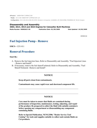
CB36B Compactor M3600001-UP (MACHINE) POWERED BY C2.2 Engine(KEBP6... 1/4 Product: COMPACTOR Model: CB-36B COMPACTOR M36 Configuration: CB36B Compactor M3600001-UP (MACHINE) POWERED BY C2.2 Engine Disassembly and Assembly C1.5 and C2.2 Engines for Caterpillar Built Machines Media Number -UENR3332-01 Publication Date -01/09/2013 Date Updated -07/06/2016 i05298454 Housing (Front) - Remove SMCS - 1151-011 Removal Procedure Start By: a. Remove the fuel injection pump. Refer to Disassembly and Assembly, "Fuel Injection Pump - Remove" for the correct procedure. b. Remove the crankshaft pulley. Refer to Disassembly and Assembly, "Crankshaft Pulley - Remove and Install" for the correct procedure. NOTICE Keep all parts clean from contaminants. Contaminants may cause rapid wear and shortened component life. NOTICE Care must be taken to ensure that fluids are contained during performance of inspection, maintenance, testing, adjusting and repair of the product. Be prepared to collect the fluid with suitable containers before opening any compartment or disassembling any component containing fluids. Dispose of all fluids according to local regulations and mandates. https://127.0.0.1/sisweb/sisweb/techdoc/techdoc_print_page.jsp?returnurl=/sis... 2023/3/20
CB36B Compactor M3600001-UP (MACHINE) POWERED BY C2.2 Engine(KEBP6... 2/4 1. If necessary, remove hydraulic pump from the front housing refer to the Original Equipment Manufactures (OEM) for the correct procedure. Illustration 1 g03343146 2. Remove nuts (1) and bolts (2). 3. Remove blanking plate (4) and blanking plate (3). 4. Remove O-ring seal (5) (not shown). 5. Remove O-ring seal (6) (not shown). 6. If necessary, remove Power Take Off (PTO) adapter (7). 7. If necessary, remove O-ring seal (8) (not shown). https://127.0.0.1/sisweb/sisweb/techdoc/techdoc_print_page.jsp?returnurl=/sis... 2023/3/20
CB36B Compactor M3600001-UP (MACHINE) POWERED BY C2.2 Engine(KEBP6... 3/4 Illustration 2 g03343478 8. Remove secondary engine speed timing sensor (11) from housing (9). Refer to Disassembly and Assembly, "Secondary Engine Speed/Timing Sensor - Remove and Install" for the correct procedure. 9. Remove secondary engine speed timing sensor (11) from housing (16). Refer to Disassembly and Assembly, "Primary Engine Speed/Timing Sensor - Remove and Install" for the correct procedure. 10. Cut cable straps (13). 11. Remove bolts (15) and remove bracket (14). 12. Remove bolts (10), bolts (18), and nuts (12) from housing (9). Note: Note position of different length bolts for installation purposes. 13. Carefully remove front housing (9) from the engine. https://127.0.0.1/sisweb/sisweb/techdoc/techdoc_print_page.jsp?returnurl=/sis... 2023/3/20
CB36B Compactor M3600001-UP (MACHINE) POWERED BY C2.2 Engine(KEBP6... 4/4 14. Remove gasket (17) (not shown). https://127.0.0.1/sisweb/sisweb/techdoc/techdoc_print_page.jsp?returnurl=/sis... 2023/3/20
CB36B Compactor M3600001-UP (MACHINE) POWERED BY C2.2 Engine(KEBP6... 1/7 Product: COMPACTOR Model: CB-36B COMPACTOR M36 Configuration: CB36B Compactor M3600001-UP (MACHINE) POWERED BY C2.2 Engine Disassembly and Assembly C1.5 and C2.2 Engines for Caterpillar Built Machines Media Number -UENR3332-01 Publication Date -01/09/2013 Date Updated -07/06/2016 i05298452 Housing (Front) - Disassemble SMCS - 1151-015 Disassembly Procedure Start By: a. Record the governor settings. Refer to Systems Operation, Testing and Adjusting, "Governor - Adjust" for the correct procedure. b. Remove the engine front housing. Refer to Disassembly and Assembly, "Housing (Front) - Remove" for the correct procedure. Personal injury can result from being struck by parts propelled by a released spring force. Make sure to wear all necessary protective equipment. Follow the recommended procedure and use all recommended tooling to release the spring force. NOTICE Keep all parts clean from contaminants. Contaminants may cause rapid wear and shortened component life. https://127.0.0.1/sisweb/sisweb/techdoc/techdoc_print_page.jsp?returnurl=/sis... 2023/3/20
CB36B Compactor M3600001-UP (MACHINE) POWERED BY C2.2 Engine(KEBP6... 2/7 Illustration 1 g03343534 https://127.0.0.1/sisweb/sisweb/techdoc/techdoc_print_page.jsp?returnurl=/sis... 2023/3/20
CB36B Compactor M3600001-UP (MACHINE) POWERED BY C2.2 Engine(KEBP6... 3/7 Illustration 2 g03343535 1. Remove spring (4) from arm (2) on the assembly of throttle control (1). 2. Remove bolts (5) and remove the assembly of throttle control (1) from front housing (3). 3. Remove gasket (6). https://127.0.0.1/sisweb/sisweb/techdoc/techdoc_print_page.jsp?returnurl=/sis... 2023/3/20
CB36B Compactor M3600001-UP (MACHINE) POWERED BY C2.2 Engine(KEBP6... 4/7 Illustration 3 g03343536 4. Remove shaft (9) from front housing (3). 5. Remove lever assembly (7) from front housing (3). 6. Remove sealing washer (8) from shaft (9). Illustration 4 g03343538 https://127.0.0.1/sisweb/sisweb/techdoc/techdoc_print_page.jsp?returnurl=/sis... 2023/3/20
CB36B Compactor M3600001-UP (MACHINE) POWERED BY C2.2 Engine(KEBP6... 5/7 7. If the engine is equipped with an angleich unit, remove angleich unit (10) from lever assembly (7). Illustration 5 g03343540 https://127.0.0.1/sisweb/sisweb/techdoc/techdoc_print_page.jsp?returnurl=/sis... 2023/3/20
CB36B Compactor M3600001-UP (MACHINE) POWERED BY C2.2 Engine(KEBP6... 6/7 Illustration 6 g03343542 8. Remove silicon rubber bung (16). 9. Disconnect spring (13) from front housing (3). 10. Remove nut (15) and remove sealing washer (14) from front housing (3). 11. Remove shaft (11) and remove lever assembly (12) from front housing (3). https://127.0.0.1/sisweb/sisweb/techdoc/techdoc_print_page.jsp?returnurl=/sis... 2023/3/20
CB36B Compactor M3600001-UP (MACHINE) POWERED BY C2.2 Engine(KEBP6... 7/7 Illustration 7 g03343543 12. The position of fuel screw (17) controls the emissions of the engine. Do not remove the fuel screw unless a different front housing will be installed. Do not adjust the fuel screw. Refer to Systems Operation, Testing and Adjusting, "Governor" for further information. 13. If necessary, remove the tamper proof cap (20), locknut (19), and sealing washer (18) from front housing (3). 14. Remove fuel screw (17). https://127.0.0.1/sisweb/sisweb/techdoc/techdoc_print_page.jsp?returnurl=/sis... 2023/3/20
CB36B Compactor M3600001-UP (MACHINE) POWERED BY C2.2 Engine(KEBP6... 1/8 Product: COMPACTOR Model: CB-36B COMPACTOR M36 Configuration: CB36B Compactor M3600001-UP (MACHINE) POWERED BY C2.2 Engine Disassembly and Assembly C1.5 and C2.2 Engines for Caterpillar Built Machines Media Number -UENR3332-01 Publication Date -01/09/2013 Date Updated -07/06/2016 i05298451 Housing (Front) - Assemble SMCS - 1151-016 Assembly Procedure Table 1 Required Tools Tool Part Number Part Description Qty A - Loctite 243 Thread Lock 1 B - Loctite 275 Thread Lock 1 Improper assembly of parts that are spring loaded can cause bodily injury. To prevent possible injury, follow the established assembly procedure and wear protective equipment. NOTICE Keep all parts clean from contaminants. Contaminants may cause rapid wear and shortened component life. https://127.0.0.1/sisweb/sisweb/techdoc/techdoc_print_page.jsp?returnurl=/sis... 2023/3/20
Suggest: For more complete manuals. Please go to the home page. https://www.ebooklibonline.com If the above button click is invalid. Please download this document first, and then click the above link to download the complete manual. Thank you so much for reading
CB36B Compactor M3600001-UP (MACHINE) POWERED BY C2.2 Engine(KEBP6... 2/8 Illustration 1 g03343543 Note: The position of fuel screw (17) controls the emissions of the engine. Ensure correct adjustment of the fuel screw. Refer to Systems Operation, Testing and Adjusting, "Governor - Adjust" for the correct procedure. 1. If the original housing has been replaced with a new housing, follow Step 1.a through Step 1.e in order to install fuel screw (17). a. Install fuel screw (17) to housing (3). b. Install a new sealing washer (18) to fuel screw (17). c. Loosely install locknut (19) to fuel screw (17). The procedure that is used to set the position of the fuel screw is described in Systems Operation, Testing and Adjusting, "Governor - Adjust" for the correct procedure. d. Do not install the tamper proof cap (20) until fuel screw (17) adjustment has been completed. e. Install a new emissions label to front housing (3). https://127.0.0.1/sisweb/sisweb/techdoc/techdoc_print_page.jsp?returnurl=/sis... 2023/3/20
CB36B Compactor M3600001-UP (MACHINE) POWERED BY C2.2 Engine(KEBP6... 3/8 Illustration 2 g03343542 https://127.0.0.1/sisweb/sisweb/techdoc/techdoc_print_page.jsp?returnurl=/sis... 2023/3/20
https://www.ebooklibonline.com Hello dear friend! Thank you very much for reading. Enter the link into your browser. The full manual is available for immediate download. https://www.ebooklibonline.com

