Caterpillar Cat CB-534 VIBRATORY COMPACTOR (Prefix 2YF) Service Repair Manual Instant Download (2YF00001 and up)
Please open the website below to get the complete manualnn// n
Download Presentation

Please find below an Image/Link to download the presentation.
The content on the website is provided AS IS for your information and personal use only. It may not be sold, licensed, or shared on other websites without obtaining consent from the author. Download presentation by click this link. If you encounter any issues during the download, it is possible that the publisher has removed the file from their server.
E N D
Presentation Transcript
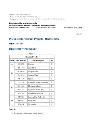
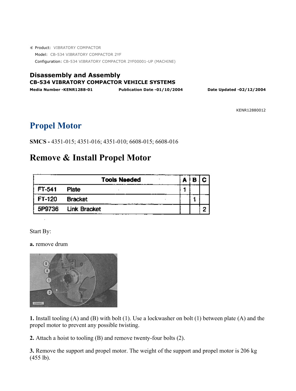
CB-534 VIBRATORY COMPACTOR 2YF00001-UP (MACHINE)(KEBP4111 - 02) ... 1/27 Product: VIBRATORY COMPACTOR Model: CB-534 VIBRATORY COMPACTOR 2YF Configuration: CB-534 VIBRATORY COMPACTOR 2YF00001-UP (MACHINE) Disassembly and Assembly CB-534 VIBRATORY COMPACTOR VEHICLE SYSTEMS Media Number -KENR1288-01 Publication Date -01/10/2004 Date Updated -02/12/2004 KENR12880012 Propel Motor SMCS - 4351-015; 4351-016; 4351-010; 6608-015; 6608-016 Remove & Install Propel Motor Start By: a. remove drum 1. Install tooling (A) and (B) with bolt (1). Use a lockwasher on bolt (1) between plate (A) and the propel motor to prevent any possible twisting. 2. Attach a hoist to tooling (B) and remove twenty-four bolts (2). 3. Remove the support and propel motor. The weight of the support and propel motor is 206 kg (455 lb). https://127.0.0.1/sisweb/sisweb/techdoc/techdoc_print_page.jsp?returnurl=/sis... 2022/7/10
CB-534 VIBRATORY COMPACTOR 2YF00001-UP (MACHINE)(KEBP4111 - 02) ... 2/27 4. Position the motor and support on blocks and install tooling (C). 5. Attach a hoist to tooling (C) and remove five bolts (3). Remove the motor from the support. The weight of the motor is 136 kg (300 lb). NOTE: To install propel motor, reverse the removal steps. End By: a. install drum Disassemble Propel Motor https://127.0.0.1/sisweb/sisweb/techdoc/techdoc_print_page.jsp?returnurl=/sis... 2022/7/10
CB-534 VIBRATORY COMPACTOR 2YF00001-UP (MACHINE)(KEBP4111 - 02) ... 3/27 Start By: a. remove propel motor NOTICE Dirt can damage motor components. Be sure the motor is clean and free of dirt and debris prior to disassembly. Perform the disassembly and assembly procedure on a clean work bench. Scribe a line on the motor case to aid the orientation of motor components on assembly. 1. Install tooling (A) and (B). Tighten tool (B) and remove retaining ring (1) with tool (C). https://127.0.0.1/sisweb/sisweb/techdoc/techdoc_print_page.jsp?returnurl=/sis... 2022/7/10
https://www.ebooklibonline.com Hello dear friend! Thank you very much for reading. Enter the link into your browser. The full manual is available for immediate download. https://www.ebooklibonline.com
CB-534 VIBRATORY COMPACTOR 2YF00001-UP (MACHINE)(KEBP4111 - 02) ... 4/27 2. Remove washer (2). 3. Use tools (B) and (D) to remove brake piston (3) from brake assembly housing (4). Remove the O-ring from the brake piston. 4. Remove bolts (5) to separate brake assembly housing (4) from bearing assembly (6). NOTE: The brake disk assembly is arranged as follows: Shim/plate/disk/plate/disk...etc. 5. Remove O-ring (7). Remove shim(s) (8), fifteen plates (9) and fourteen disks (10). 6. Remove screw (12) and drain the oil. Remove sixteen bolts (13) to remove bearing assembly (11) from cam assembly (14). https://127.0.0.1/sisweb/sisweb/techdoc/techdoc_print_page.jsp?returnurl=/sis... 2022/7/10
CB-534 VIBRATORY COMPACTOR 2YF00001-UP (MACHINE)(KEBP4111 - 02) ... 5/27 7. Remove O-ring (15). Use tool (E) to measure the height of pins (16) from the flange face (19) to the top of the pin. Retain this measurement for reassembly purposes. Remove two pins (16). Remove disk (17) and four springs (18). 8. Remove four bolts (20) to remove bearing (21) from plate (22). 9. Remove one O-ring (24) and two O-rings (25). Use tool (F) to remove five rings (23) from bearing (21). 10. Remove plate (22) from cylinder block assembly (26). https://127.0.0.1/sisweb/sisweb/techdoc/techdoc_print_page.jsp?returnurl=/sis... 2022/7/10
CB-534 VIBRATORY COMPACTOR 2YF00001-UP (MACHINE)(KEBP4111 - 02) ... 6/27 11. Remove two pistons (27). Remove two plugs (28). 12. Remove cam assembly (14) and cylinder block assembly (26) from bearing assembly (30) and shaft (29). 13. Remove two roll pins (34). Remove four guide rings (31) and piston assembly (33). Remove roller (32). 14. Use tool (G) to remove piston ring (35) from piston (36). Remove piston segment (37). https://127.0.0.1/sisweb/sisweb/techdoc/techdoc_print_page.jsp?returnurl=/sis... 2022/7/10
CB-534 VIBRATORY COMPACTOR 2YF00001-UP (MACHINE)(KEBP4111 - 02) ... 7/27 15. Remove O-ring (38). Separate split washer (39) from shaft (41). Remove shim(s) (40). Remove bearing assembly (30) from shaft (41). 16. Remove bearing cone (42) from bearing cup (43). 17. Use tool (H) to remove bearing cup (43). 18. Remove seal (44) from bearing assembly (30). https://127.0.0.1/sisweb/sisweb/techdoc/techdoc_print_page.jsp?returnurl=/sis... 2022/7/10
CB-534 VIBRATORY COMPACTOR 2YF00001-UP (MACHINE)(KEBP4111 - 02) ... 8/27 19. Use tool (I) and a press to remove the seal, support, O-ring and bearing from bearing assembly (30). 20. Use tool (J) to remove deflector (45) from shaft (41). Assemble Propel Motor NOTE: Thoroughly clean all parts prior to assembly. Perform assembly on a clean work bench, free of dirt and dust. Coat all contact surfaces with a light coat of hydraulic oil before assembly. https://127.0.0.1/sisweb/sisweb/techdoc/techdoc_print_page.jsp?returnurl=/sis... 2022/7/10
CB-534 VIBRATORY COMPACTOR 2YF00001-UP (MACHINE)(KEBP4111 - 02) ... 9/27 NOTICE Deflector (45) must be replaced if it is removed from the shaft. NOTE: The raised edge on deflector (45) faces the splined end of the shaft. 1. Use a press and tool (A) to press deflector (45) on the shaft. 2. Use a press and tool (B) to install the bearing in the bearing assembly (30). Install the O-ring and support in bearing assembly (30). Pack the outermost bearing with 2S3230 Bearing Lubricant. NOTICE Before the seal is installed in Step 3, the bearing must be packed with 2S3230 Bearing Lubricant. If the bearing is not packed with grease at this time, premature failure may result. 3. Use tool (C) to install the seal in bearing assembly (30). https://127.0.0.1/sisweb/sisweb/techdoc/techdoc_print_page.jsp?returnurl=/sis... 2022/7/10
CB-534 VIBRATORY COMPACTOR 2YF00001-UP (MACHINE)(KEBP4111 - 0... 10/27 4. Use tool (B) to install seal (44) in bearing assembly (30). 5. Lower the temperature of bearing cup (43) and install in bearing assembly (30). Install bearing cone (42) in the bearing cup. NOTE: If the original bearings are used at assembly, use the same shim(s) that were removed at the time of disassembly. If the bearings were replaced, the shim(s) will have to be replaced with new shim(s). 6. Use tool (D) to lower bearing assembly (30) on shaft (41). Install split washer (39) on shaft (49). Install O-ring (38). 7. Use a feeler gauge to measure the distance between the split ring and the bearing cone. The thickness of shim(s) (40) will be equal to the distance measured plus 0.1 mm (0.004 in) maximum. 8. Remove split washer (39) and install shim(s) (40) with the thick shim on the bearing side. Compress the bearings in a press with 8000 kg (17,600 lbs) and then install the split washer. 9. Rotate the shaft, if it does not rotate smoothly, add or subtract shims as needed. https://127.0.0.1/sisweb/sisweb/techdoc/techdoc_print_page.jsp?returnurl=/sis... 2022/7/10
CB-534 VIBRATORY COMPACTOR 2YF00001-UP (MACHINE)(KEBP4111 - 0... 11/27 10. Assemble cylinder block assembly as follows: a. Use tool (E) to install piston ring (35) on piston (36). Install piston segment (37). b. Install piston (37) and roller (32) into the cylinder block. c. Install guide rings (31) and insert roll pins (34). 11. Install cylinder block assembly (26) on the shaft. Install cam (14) on the bearing assembly. 12. Install two plugs (28) and two pistons (27) in the plate. 13. Install plate (22) on the shaft and cylinder block assembly. https://127.0.0.1/sisweb/sisweb/techdoc/techdoc_print_page.jsp?returnurl=/sis... 2022/7/10
CB-534 VIBRATORY COMPACTOR 2YF00001-UP (MACHINE)(KEBP4111 - 0... 12/27 14. Install one O-ring (24) and two O-rings (25). Use tool (G) to install five segment rings (23). 15. Install bearing (21) in plate (22). Install four bolts (20). 16. Insert four springs (18) into the spring pockets. Position disk (17) and press pins (16) to the same depth measures in Step 7 of the disassembly of the propel motor, in this module. Install O- ring (15). 17. Install distribution bearing assembly (11) on cam (14) and install sixteen bolts (13). Tighten sixteen bolts (13) to a torque of 300 N m (221 lb ft). Install screw (12). https://127.0.0.1/sisweb/sisweb/techdoc/techdoc_print_page.jsp?returnurl=/sis... 2022/7/10
CB-534 VIBRATORY COMPACTOR 2YF00001-UP (MACHINE)(KEBP4111 - 0... 13/27 18. Install O-ring (7). Install brake plate (9) and then brake disk (10). Continue stacking the plates and disks in an alternating fashion until fifteen plates and fourteen disks are installed on the spline. Install the original shim(s) if the plates and disks were not changed. 19. Shim(s) (8) will have to be changed if new plates (9) and disks (10) were installed. the thickness of shim(s), in this case, will be determined in Step 22. Do not install any shims at this time. 20. Install brake assembly housing (4) on being assembly (6) and fasten with eight bolts (5). Tighten eight bolts (5) to a torque of 300 N m (221 lb ft). 21. Install the O-ring on the piston and install piston (3) in the brake housing. Install washer (2). Use tool (J) to install retaining ring (1). https://127.0.0.1/sisweb/sisweb/techdoc/techdoc_print_page.jsp?returnurl=/sis... 2022/7/10
CB-534 VIBRATORY COMPACTOR 2YF00001-UP (MACHINE)(KEBP4111 - 0... 14/27 22. Take a measurement of dimension "X". The shims will equal the dimension "X" minus 14.5 mm (0.057 in). Go back to Step 18 and install the shims and repeat Steps 19 through 21. End By: a. install propel motor Disassemble Drum Start By: a. remove drum b. remove propel motor https://127.0.0.1/sisweb/sisweb/techdoc/techdoc_print_page.jsp?returnurl=/sis... 2022/7/10
CB-534 VIBRATORY COMPACTOR 2YF00001-UP (MACHINE)(KEBP4111 - 0... 15/27 Remove drain plug (3) slowly. If the drum has been in use and is hot, the oil may be hot and under pressure. Even if the drum has not been in use, remove the plug slowly to relieve pressure. 1. Position the drain plug at the lowest point and drain the oil from the vibrator. The capacity of the vibrator unit is 11 Liters (3 U.S. Gallons). NOTE: Before removing any parts, mark mating parts as to their relative position to aid in assembly. 2. Remove nut (1) and wheel (2). Wheel (2) is keyed to the shaft. 3. Remove key (5). Remove bolts (6) and plate (4). 4. Using two people, support the weight of support (9) and remove twenty-five bolts (8) and support (9). The weight of the support is 32 kg (70 lb). Remove plates (7) with the support. https://127.0.0.1/sisweb/sisweb/techdoc/techdoc_print_page.jsp?returnurl=/sis... 2022/7/10
CB-534 VIBRATORY COMPACTOR 2YF00001-UP (MACHINE)(KEBP4111 - 0... 16/27 5. Remove twenty-five bolts (10) and remove bearing (11). 6. Attach a lifting device to plate (12) and remove twenty-four bolts (13). Remove plate (12). The weight of the plate is 73 kg (165 lb). 7. Remove twelve bolts (14) and remove plate (15). 8. Remove four nuts and tab locks (16) and remove the shaft. 9. Bend the lock tabs back and remove sixteen nuts (17) and the lock plates. 10. Remove two bolts (18) and install tooling (A) using bolts 50 mm (1 in) in place of bolts (18). Remove all but two nuts (19) at the ten and two o'clock positions. 11. Remove four bolts (20) and clamp (21). https://127.0.0.1/sisweb/sisweb/techdoc/techdoc_print_page.jsp?returnurl=/sis... 2022/7/10
CB-534 VIBRATORY COMPACTOR 2YF00001-UP (MACHINE)(KEBP4111 - 0... 17/27 12. Position a lift truck with the forks supporting the vibration unit and connect tool (E) to tool (D). Connect tool (E) to the mast of the lift truck and snug up tool (E) to support the weight of the vibration unit. Install blocking as shown. NOTICE While removing the vibration unit in Step 13, watch on the other side of the drum for clearances of the sight glass and drain plug tubes. Take care not to make sudden drastic moves or damage may result. 13. Remove the remaining two nuts and push all of the screws back out of the holes. Use the lift truck to raise the vibration unit slightly and remove the vibration unit. The weight of the vibration unit is 215 kg (475 lb). 14. Position the vibration unit on tool (C) or a similar stand. Remove tooling (A) and install three forcing screws (26) and separate the housings. Dust seal (25) will be forced off as the housings are separated. https://127.0.0.1/sisweb/sisweb/techdoc/techdoc_print_page.jsp?returnurl=/sis... 2022/7/10
CB-534 VIBRATORY COMPACTOR 2YF00001-UP (MACHINE)(KEBP4111 - 0... 18/27 15. Install tooling (A) with three bolts (26) and attach a lifting device to tooling (A). Remove the housing. The weight of the housing is 64 kg (140 lb). 16. Turn the housing over if the seal and bearing are to be replaced. Remove the seal with a punch. Remove four bolts (29) and bearing cover (30). Remove O-ring (27) and replace as necessary. Turn the housing over and use tooling (D) to press the bearing out. NOTE: Shim (32) is used to set the end play of the shaft. Save this shim for the assembly of the unit. 17. Secure the housing to the stand (C) using three bolts (33). Remove shim (32). 18. Use bolts (20) from Step 11 to fasten tooling (A). Attach a lifting device to tooling (A) and raise vibratory shaft (34) out of the housing. You may need to tap the outer edges of the housing with a soft-faced hammer as the shaft is being raised. The weight of the shaft assembly is 70 kg (155 lb). https://127.0.0.1/sisweb/sisweb/techdoc/techdoc_print_page.jsp?returnurl=/sis... 2022/7/10
CB-534 VIBRATORY COMPACTOR 2YF00001-UP (MACHINE)(KEBP4111 - 0... 19/27 19. Inspect the bearing and seal in the housing and repeat Step 16, if necessary. NOTE: Step 20 need not be performed if there are no leaks around tubes (35) and (36). 20. Remove tubes (35) and (36). Replace the O-rings under the tubes. 21. Place the shaft assembly in a vise. Notice marks (37) are for assembly purposes. 22. Bend ten lock tabs (38) back and remove ten nuts (39). Use another person to hold the assembly together and remove the remaining nuts and bolts. Remove shaft (40). Remove the bushing from the shaft (40) if necessary. 23. Remove shaft (42) and weight (43). 24. Disassemble shaft (40) as follows: https://127.0.0.1/sisweb/sisweb/techdoc/techdoc_print_page.jsp?returnurl=/sis... 2022/7/10
CB-534 VIBRATORY COMPACTOR 2YF00001-UP (MACHINE)(KEBP4111 - 0... 20/27 a. Remove four bolts (45) and loosen the remaining two bolts. b. Install forcing screws (47). Alternately tighten the forcing screws while loosening screws (48). Remove bearing plate (49). c. Place bearing plate (49) in a press and remove bushing (50). d. Remove spring (51) and shaft (52). Remove pin (53) to remove spur (54). https://127.0.0.1/sisweb/sisweb/techdoc/techdoc_print_page.jsp?returnurl=/sis... 2022/7/10
Suggest: For more complete manuals. Please go to the home page. https://www.ebooklibonline.com If the above button click is invalid. Please download this document first, and then click the above link to download the complete manual. Thank you so much for reading
CB-534 VIBRATORY COMPACTOR 2YF00001-UP (MACHINE)(KEBP4111 - 0... 21/27 e. Remove race (57) from shaft (40). Replace seal (55) if necessary. Assemble Drum NOTICE Before assembly, thoroughly clean the housings and all parts. Perform the assembly on clean workbench. Apply a thin coat of oil to bushings and other metal to metal contact surfaces. 1. Press bearings (31) and the seals into both housings. Install bearing caps (30) with bolts (29). Install O-ring (27) with grease to hold it in place and install dowels (28), if they were removed. 2. Position the bottom housing on the stand. 3. Install seal (55) and race (57) on shaft (40). https://127.0.0.1/sisweb/sisweb/techdoc/techdoc_print_page.jsp?returnurl=/sis... 2022/7/10
CB-534 VIBRATORY COMPACTOR 2YF00001-UP (MACHINE)(KEBP4111 - 0... 22/27 4. Position spur (54) on shaft (52) and install pin (53). Install spring (51) and shaft (52) in the shaft. 5. Press bushing (50) into plate (49). 6. Install bearing (49) on shaft (40). 7. Install bushing (50) in shaft (42). https://127.0.0.1/sisweb/sisweb/techdoc/techdoc_print_page.jsp?returnurl=/sis... 2022/7/10
https://www.ebooklibonline.com Hello dear friend! Thank you very much for reading. Enter the link into your browser. The full manual is available for immediate download. https://www.ebooklibonline.com

