Caterpillar Cat 973 TRACK LOADER (Prefix 91L) Service Repair Manual Instant Download
Please open the website below to get the complete manualnn//
Download Presentation

Please find below an Image/Link to download the presentation.
The content on the website is provided AS IS for your information and personal use only. It may not be sold, licensed, or shared on other websites without obtaining consent from the author. Download presentation by click this link. If you encounter any issues during the download, it is possible that the publisher has removed the file from their server.
E N D
Presentation Transcript
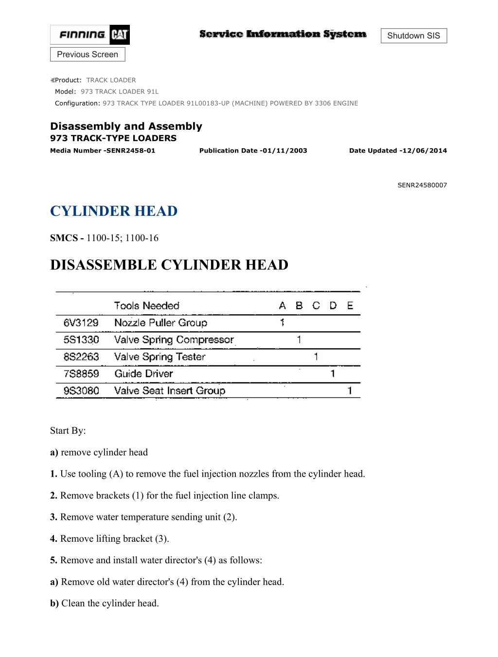
973 TRACK TYPE LOADER 91L00183-UP (MACHINE) POWERED BY 3306 EN... 1/6 Shutdown SIS Previous Screen Product: TRACK LOADER Model: 973 TRACK LOADER 91L Configuration: 973 TRACK TYPE LOADER 91L00183-UP (MACHINE) POWERED BY 3306 ENGINE Disassembly and Assembly 973 TRACK-TYPE LOADERS Media Number -SENR2458-01 Publication Date -01/11/2003 Date Updated -12/06/2014 SENR24580007 CYLINDER HEAD SMCS - 1100-15; 1100-16 DISASSEMBLE CYLINDER HEAD Start By: a) remove cylinder head 1. Use tooling (A) to remove the fuel injection nozzles from the cylinder head. 2. Remove brackets (1) for the fuel injection line clamps. 3. Remove water temperature sending unit (2). 4. Remove lifting bracket (3). 5. Remove and install water director's (4) as follows: a) Remove old water director's (4) from the cylinder head. b) Clean the cylinder head. https://127.0.0.1/sisweb/sisweb/techdoc/techdoc_print_page.jsp?returnurl=/sis... 2021/11/15
973 TRACK TYPE LOADER 91L00183-UP (MACHINE) POWERED BY 3306 EN... 2/6 c) Install new water director's in the cylinder head with the notch in the water director in alignment with the "V" mark on the cylinder head. Install the water director's to a depth of 0.8 0.6 mm (.031 .023 in) below the surface of the cylinder head. 6. Use tooling (B) to put valve spring (6) in compression. Remove locks (5) from the valve stem. Carefully remove tooling (13), rotocoil, spring and valve. Put identification on the valves with respect to their location in the cylinder head. Remove the remainder of the valves the same way. 7. Use tooling (C) to check the valve springs. The spring force is 257 25 N (57.6 5.6 lb). The length of spring under test force is 44.86 mm (1.766 in). The free length after test is 52.1 (2.05 in). Check all the valve springs. https://127.0.0.1/sisweb/sisweb/techdoc/techdoc_print_page.jsp?returnurl=/sis... 2021/11/15
973 TRACK TYPE LOADER 91L00183-UP (MACHINE) POWERED BY 3306 EN... 3/6 8. Use tooling (D) to remove the valve guides from the cylinder head. 9. Use tooling (E) to remove the valve seat inserts from the cylinder head. 10. Clean and remove any rough places (burrs) from the valve seat bores. NOTE: For reconditioning information of the cylinder hand see SERVICE TRAINING MEETING GUIDE Form No. JEG02327. ASSEMBLE CYLINDER HEAD https://127.0.0.1/sisweb/sisweb/techdoc/techdoc_print_page.jsp?returnurl=/sis... 2021/11/15
https://www.ebooklibonline.com Hello dear friend! Thank you very much for reading. Enter the link into your browser. The full manual is available for immediate download. https://www.ebooklibonline.com
973 TRACK TYPE LOADER 91L00183-UP (MACHINE) POWERED BY 3306 EN... 4/6 *The 8S2252 Carbon Seal Tool must have a modification made to it before it can be used with the 8N7002 Fuel Injection Nozzle. Special Instruction Form NO. SEHS7292 has the information needed to make the modification to the tool. 1. Lower the temperature of (freeze) the new valve seat inserts. Use tooling (A) to install the new valve seat inserts. Do not increase the diameter of the extractor in the valve seat insert when the insert is installed in the cylinder head. 2. Put clean oil on the outside diameter of the valve guides. Use tooling (B) to install valve guides (1) in the cylinder head. Tooling (B) will install the valve guides so dimension "X" will be correct. Dimension "X" must be 22.23 0.25 mm (.875 .010 in). The minimum inside diameter of the valve guides after installation must be 9.456 mm (.3723 in). Clean the valve guides after installation. 3. Grind the valve seat inserts according to specifications given in SPECIFICATIONS section. 4. Put clean engine oil on the valve stems. Install the valve, then install the seal, spring and rotocoil on the valve stem. https://127.0.0.1/sisweb/sisweb/techdoc/techdoc_print_page.jsp?returnurl=/sis... 2021/11/15
973 TRACK TYPE LOADER 91L00183-UP (MACHINE) POWERED BY 3306 EN... 5/6 Locks can be thrown from the valve when the compressor is released, if they are not in their correct position on the valve stem. 5. Put tooling (C) in position on the valve spring and put the spring in compression. Use tooling (D) to install the locks on the valve stem. 6. Remove tooling (D) and hit the top of the valve with a plastic hammer to be sure the locks are in their correct position on the valve. 7. Do Steps 4, 5 and 6 again for the remainder of the valves. 8. Install brackets (2) for the fuel injection line clamps on the cylinder head. 9. Put 5P3413 Pipe Sealant on the threads of water temperature sending unit (3) and install the sending unit in the cylinder head. 10. Install lifting brackets (4) on the cylinder head. 11. Use tool (E) to install carbon dam (5) on the fuel injection nozzles. Install seal (6) on the fuel injection nozzles. 12. Put fuel injection nozzles (7) in position in the cylinder head and install the bolt that holds each nozzle in place. End By: a) install cylinder head https://127.0.0.1/sisweb/sisweb/techdoc/techdoc_print_page.jsp?returnurl=/sis... 2021/11/15
973 TRACK TYPE LOADER 91L00183-UP (MACHINE) POWERED BY 3306 EN... 6/6 Copyright 1993 - 2021 Caterpillar Inc. Mon Nov 15 23:38:48 UTC+0800 2021 All Rights Reserved. Private Network For SIS Licensees. https://127.0.0.1/sisweb/sisweb/techdoc/techdoc_print_page.jsp?returnurl=/sis... 2021/11/15
973 TRACK TYPE LOADER 91L00183-UP (MACHINE) POWERED BY 3306 EN... 1/2 Shutdown SIS Previous Screen Product: TRACK LOADER Model: 973 TRACK LOADER 91L Configuration: 973 TRACK TYPE LOADER 91L00183-UP (MACHINE) POWERED BY 3306 ENGINE Disassembly and Assembly 973 TRACK-TYPE LOADERS Media Number -SENR2458-01 Publication Date -01/11/2003 Date Updated -12/06/2014 SENR24580008 FAN BELTS SMCS - 1357-11; 1357-12 REMOVE FAN BELTS 1. Remove upper fan guard (1). 2. Loosen nuts (2) on the adjustment rod and the mounting bolt for the alternator. 3. Move fan belts (3) off the pulleys and over the fan to remove. INSTALL FAN BELTS NOTE: When a replacement of one belt in a V-belt set is necessary, a replacement of the complete set must be made. 1. Install fan belts (1) over the fan and on to the pulleys. Adjust the fan belts. See the V-BELT TENSION CHART at the bottom of the page. Tighten nuts (2) on the adjustment rod and the mounting bolt for the alternator after the belts are adjusted. https://127.0.0.1/sisweb/sisweb/techdoc/techdoc_print_page.jsp?returnurl=/sis... 2021/11/15
973 TRACK TYPE LOADER 91L00183-UP (MACHINE) POWERED BY 3306 EN... 2/2 NOTE: When the tension on a V-belt set is measured, measure the belt furthest from the engine block. 2. Install the upper fan guard. Copyright 1993 - 2021 Caterpillar Inc. Mon Nov 15 23:39:44 UTC+0800 2021 All Rights Reserved. Private Network For SIS Licensees. https://127.0.0.1/sisweb/sisweb/techdoc/techdoc_print_page.jsp?returnurl=/sis... 2021/11/15
973 TRACK TYPE LOADER 91L00183-UP (MACHINE) POWERED BY 3306 EN... 1/3 Shutdown SIS Previous Screen Product: TRACK LOADER Model: 973 TRACK LOADER 91L Configuration: 973 TRACK TYPE LOADER 91L00183-UP (MACHINE) POWERED BY 3306 ENGINE Disassembly and Assembly 973 TRACK-TYPE LOADERS Media Number -SENR2458-01 Publication Date -01/11/2003 Date Updated -12/06/2014 SENR24580009 FAN SMCS - 1356-11; 1356-12 REMOVE FAN 1. Remove the muffler and hood. Weight of the hood is approximately 34 kg (74 lb). 2. Drain approximately 11.4 liter (3 U.S. gal) from the radiator. 3. Disconnect top radiator line (1) from the radiator. Disconnect oil line (2) from the top of the transmission oil cooler. 4. Remove top half (3) of the fan guard. 5. Loosen the nuts on belt adjuster (4) and move the fan belts off the fan drive pulley toward the engine. Fasten a strap and hoist to the fan drive adapter as shown. 6. Remove four bolts (5) and spacer (6). Remove the fan drive and fan as a unit. Weight is approximately 56 kg (125 lb). 7. Remove bolts (7) and remove fan (8) from the fan drive. Weight of the fan is approximately 365 kg (80 lb). https://127.0.0.1/sisweb/sisweb/techdoc/techdoc_print_page.jsp?returnurl=/sis... 2021/11/15
973 TRACK TYPE LOADER 91L00183-UP (MACHINE) POWERED BY 3306 EN... 2/3 INSTALL FAN CAUTION Do not use a fan that is bent, damaged or makes contact with any other part of the engine. Install fans which have the identification "FRONT" toward the radiator. 1. Put fan (1) in position on the fan drive adapter and install bolts (2). 2. Fasten a strap and hoist to the fan and fan drive. Put the fan and fan drive in position on the engine. Put fan belts (3) over the fan drive as shown before spacer (4) is put in position. Put spacer (4) in position and install the bolts that hold the fan drive and spacer in place. 3. Connect top radiator line (5) to the radiator. Connect oil line (6) to the top of the transmission oil cooler. 4. Install top fan guard (7). https://127.0.0.1/sisweb/sisweb/techdoc/techdoc_print_page.jsp?returnurl=/sis... 2021/11/15
973 TRACK TYPE LOADER 91L00183-UP (MACHINE) POWERED BY 3306 EN... 3/3 5. Put fan belts (3) in position on the pulley and adjust the belts to the correct tension. See FAN BELT INSTALLATION. 6. Fill the radiator to the correct level with coolant. 7. Install the hood and muffler. Weight of the hood is approximately 34 kg (74 lb). Copyright 1993 - 2021 Caterpillar Inc. Mon Nov 15 23:40:39 UTC+0800 2021 All Rights Reserved. Private Network For SIS Licensees. https://127.0.0.1/sisweb/sisweb/techdoc/techdoc_print_page.jsp?returnurl=/sis... 2021/11/15
973 TRACK TYPE LOADER 91L00183-UP (MACHINE) POWERED BY 3306 EN... 1/7 Shutdown SIS Previous Screen Product: TRACK LOADER Model: 973 TRACK LOADER 91L Configuration: 973 TRACK TYPE LOADER 91L00183-UP (MACHINE) POWERED BY 3306 ENGINE Disassembly and Assembly 973 TRACK-TYPE LOADERS Media Number -SENR2458-01 Publication Date -01/11/2003 Date Updated -12/06/2014 SENR24580010 FAN DRIVE SMCS - 1359-16; 1359-11; 1359-12; 1359-15 REMOVE FAN DRIVE 1. Remove the muffler and hood. The weight of the hood is approximately 34 kg (74 lb). 2. Loosen the nuts on fan belt adjuster (1). 3. Remove upper fan guard (2). 4. Fasten a strap and hoist to fan adapter (3) and remove bolts (4) that hold the fan adapter to the fan drive. Carefully lower the fan drive into the fan guard. The weight of the fan is approximately 36 kg (80 lb). CAUTION Be extra careful not to damage the radiator. 5. Move fan belts (5) off the fan drive pulley. 6. Fasten a strap and hoist to fan drive (6). Remove the four bolts that hold the fan drive and spacer (7) in place. Remove fan drive (6) and spacer (7). https://127.0.0.1/sisweb/sisweb/techdoc/techdoc_print_page.jsp?returnurl=/sis... 2021/11/15
973 TRACK TYPE LOADER 91L00183-UP (MACHINE) POWERED BY 3306 EN... 2/7 INSTALL FAN DRIVE 1. Fasten a strap and hoist to fan drive (1). Put the fan drive and spacer (2) in position on the engine and install the bolts that hold them in place. 2. Move fan belts (3) into position on the fan drive pulley. 3. Fasten a strap and hoist adapter (4) for the fan. Carefully put the adapter and fan in position on the fan drive and install the bolts that hold the adapter to the fan drive. 4. Install upper fan guard (5). 5. Adjust the fan belt tension. See INSTALL FAN BELTS. When the fan belt tension is correct, tighten nuts (6) on the adjustment rod. 6. Install the hood and muffler. The weight of the hood is approximately 34 kg (74 lb). https://127.0.0.1/sisweb/sisweb/techdoc/techdoc_print_page.jsp?returnurl=/sis... 2021/11/15
973 TRACK TYPE LOADER 91L00183-UP (MACHINE) POWERED BY 3306 EN... 3/7 DISASSEMBLE FAN DRIVE Start By: a) remove fan drive 1. Remove O-ring seal (2) from around the bearing. 2. Bend the tabs on lock (1) down. 3. Remove the bolts, lock (1) and washer (3). 4. Remove pulley (4), the spacer and the hub from shaft assembly (5). 5. Remove bearing (6) from the hub. Remove the pulley from the hub. NOTE: Bearing (7) and lip-type seal (8) from shaft assembly (5). https://127.0.0.1/sisweb/sisweb/techdoc/techdoc_print_page.jsp?returnurl=/sis... 2021/11/15
973 TRACK TYPE LOADER 91L00183-UP (MACHINE) POWERED BY 3306 EN... 4/7 6. Remove bearing (7) and lip-type seal (8) can stay with the pulley and hub when it is removed. 7. Remove the spacer from the shaft assembly. ASSEMBLE FAN DRIVE 1. Install pulley (1) on hub (2) as shown. NOTE: The pulley must be installed on the hub with the spacer down against the shoulder of the hub. https://127.0.0.1/sisweb/sisweb/techdoc/techdoc_print_page.jsp?returnurl=/sis... 2021/11/15
973 TRACK TYPE LOADER 91L00183-UP (MACHINE) POWERED BY 3306 EN... 5/7 2. Install the bearing in the hub. 3. Use tooling (A) to install lip-type seal (4) in the hub with the lip of the seal up. The top of the seal must be even with the end of the hub. 4. Put 5P960 Multi-purpose Type Grease on the lip of the seal. 5. Install spacer (3) in seal (4). NOTE: Make sure mounting bolts (7) are put in position before the pulley and hub are installed on the shaft. 6. Put pulley and hub assembly (5) on shaft assembly (6). https://127.0.0.1/sisweb/sisweb/techdoc/techdoc_print_page.jsp?returnurl=/sis... 2021/11/15
973 TRACK TYPE LOADER 91L00183-UP (MACHINE) POWERED BY 3306 EN... 6/7 7. Install spacer (8) on the shaft assembly. 8. Fill the hub with 5P960 Multi-purpose Type Grease. 9. Put bearings (9) in position in the hub. Make sure the bearing makes a seat in the counterbore of the hub. 10. Put washer (10) in position on the bearing. 11. Install lock (13) and bolts (12). Bend the tabs on the lock around the bolts. 12. Install O-ring seal (11) on the hub. End By: a) install fan drive https://127.0.0.1/sisweb/sisweb/techdoc/techdoc_print_page.jsp?returnurl=/sis... 2021/11/15
973 TRACK TYPE LOADER 91L00183-UP (MACHINE) POWERED BY 3306 EN... 7/7 Copyright 1993 - 2021 Caterpillar Inc. Mon Nov 15 23:41:35 UTC+0800 2021 All Rights Reserved. Private Network For SIS Licensees. https://127.0.0.1/sisweb/sisweb/techdoc/techdoc_print_page.jsp?returnurl=/sis... 2021/11/15
973 TRACK TYPE LOADER 91L00183-UP (MACHINE) POWERED BY 3306 EN... 1/2 Shutdown SIS Previous Screen Product: TRACK LOADER Model: 973 TRACK LOADER 91L Configuration: 973 TRACK TYPE LOADER 91L00183-UP (MACHINE) POWERED BY 3306 ENGINE Disassembly and Assembly 973 TRACK-TYPE LOADERS Media Number -SENR2458-01 Publication Date -01/11/2003 Date Updated -12/06/2014 SENR24580011 PRESSURE RELIEF VALVE SMCS - 1370-11; 1370-12 REMOVE PRESSURE RELIEF VALVE Release the pressure in the cooling system by slow removal of the radiator cap. 1. Remove cap (1). 2. Remove valve (2), gasket (3), plate (4) and gasket (5). https://127.0.0.1/sisweb/sisweb/techdoc/techdoc_print_page.jsp?returnurl=/sis... 2021/11/15
973 TRACK TYPE LOADER 91L00183-UP (MACHINE) POWERED BY 3306 EN... 2/2 INSTALL PRESSURE RELIEF VALVE 1. Inspect the valve (1), plate (3) and gaskets (2) and (4). Make a replacement if necessary. 2. Install gasket (4) and plate (3). Install plate (3) to face up according to the indication on the plate. 3. Install gasket (2) and valve (1). Install valve (1) as shown. 4. Install the cap. 5. Fill the radiator according to the MAINTENANCE GUIDE. Copyright 1993 - 2021 Caterpillar Inc. Mon Nov 15 23:42:31 UTC+0800 2021 All Rights Reserved. Private Network For SIS Licensees. https://127.0.0.1/sisweb/sisweb/techdoc/techdoc_print_page.jsp?returnurl=/sis... 2021/11/15
973 TRACK TYPE LOADER 91L00183-UP (MACHINE) POWERED BY 3306 EN... 1/7 Shutdown SIS Previous Screen Product: TRACK LOADER Model: 973 TRACK LOADER 91L Configuration: 973 TRACK TYPE LOADER 91L00183-UP (MACHINE) POWERED BY 3306 ENGINE Disassembly and Assembly 973 TRACK-TYPE LOADERS Media Number -SENR2458-01 Publication Date -01/11/2003 Date Updated -12/06/2014 SENR24580012 RADIATOR AND TRANSMISSION OIL COOLER SMCS - 1353; 1375-12; 1375-11 REMOVE RADIATOR AND TRANSMISSION OIL COOLER 1. Remove the muffler and hood. The weight of the hood is approximately 34 kg (74 lb). Remove the rear guard below the engine. The weight of the engine is approximately 45 kg (100 lb). 2. Drain the radiator and transmission. The capacity of the radiator is approximately 49 liters (13 U.S. gal). The capacity of the transmission is approximately 60.0 liters (15.8 U.S. gal). 3. Remove brackets (2) at the bottom of the grille. Pull grille (1) out at the bottom and use two people to remove it. The weight is approximately 36 kg (80 lb). 4. Remove six bolts (3), two bolts (5) and mounting bracket (4) for the radiator. 5. Remove nuts (6) that hold the hydraulic oil cooler in place and move the oil cooler away from the radiator. 6. Remove lower radiator elbow (7). Disconnect transmission oil cooler line (8) from nipple (9) and remove the nipple from the oil cooler. 7. Loosen hose clamp (10) and disconnect the top radiator hose from the radiator. Disconnect transmission oil cooler line (11) from the nipple (12) and remove the nipple from the oil cooler. 8. Fasten tooling (A), chains and a hoist to the radiator. Remove bolts (13) from both sides of the radiator and remove the radiator and transmission oil cooler as a unit. The weight is approximately 268 kg (595 lb). https://127.0.0.1/sisweb/sisweb/techdoc/techdoc_print_page.jsp?returnurl=/sis... 2021/11/15
973 TRACK TYPE LOADER 91L00183-UP (MACHINE) POWERED BY 3306 EN... 2/7 INSTALL RADIATOR AND TRANSMISSION OIL COOLER https://127.0.0.1/sisweb/sisweb/techdoc/techdoc_print_page.jsp?returnurl=/sis... 2021/11/15
973 TRACK TYPE LOADER 91L00183-UP (MACHINE) POWERED BY 3306 EN... 3/7 1. Fasten tooling (A), chains and a hoist to radiator (1). Put the radiator and transmission oil cooler in position in the radiator guard and install the four bolts in the top of the radiator. The weight of the radiator and transmission oil cooler is approximately 268 kg (595 lb). 2. Put hydraulic oil cooler (2) in position on the radiator and install the nuts on the studs to hold it in place. 3. Put radiator mounting bracket (3) in position and install the bolts that hold it in place. 4. Be sure the O-ring seal is in position on nipple (4) and install the nipple in the transmission oil cooler. Connect oil line (5) to the nipple. Install the gasket and lower radiator elbow (6). 5. Connect top radiator hose (7) to the radiator. Be sure the O-ring seal is in position on nipple (8) and install the nipple in the transmission oil cooler. Connect oil line (9) to the nipple. 6. Use two people to put grille (10) in position on the radiator guard and install brackets (11) to hold it in place. 7. Fill the transmission with oil to the correct level. 8. Fill the cooling system with coolant. 9. Install the hood and muffler. The weight of the hood is approximately 34 kg (74 lb). Install the rear guard below the engine. Weight is approximately 45 kg (100 lb). https://127.0.0.1/sisweb/sisweb/techdoc/techdoc_print_page.jsp?returnurl=/sis... 2021/11/15
973 TRACK TYPE LOADER 91L00183-UP (MACHINE) POWERED BY 3306 EN... 4/7 SEPARATION OF RADIATOR AND TRANSMISSION OIL COOLER Start By: a) remove radiator and transmission oil cooler 1. Remove channel (1). 2. Remove eleven bolts (2), corner bracket (3) and strip (4). 3. Remove two bolts (5) and the threaded strip. 4. Remove eleven bolts (7), strip (8) and corner bracket (6). 5. Hold the oil cooler and remove three bolts (9) that hold it to the top tank of the radiator. 6. Slide transmission oil cooler (10) out far enough to install tool (A) and fasten a hoist. Remove the transmission oil cooler from the radiator assembly. Weight is approximately 68 kg (150 lb). https://127.0.0.1/sisweb/sisweb/techdoc/techdoc_print_page.jsp?returnurl=/sis... 2021/11/15
973 TRACK TYPE LOADER 91L00183-UP (MACHINE) POWERED BY 3306 EN... 5/7 CONNECTION OF RADIATOR AND TRANSMISSION OIL COOLER https://127.0.0.1/sisweb/sisweb/techdoc/techdoc_print_page.jsp?returnurl=/sis... 2021/11/15
973 TRACK TYPE LOADER 91L00183-UP (MACHINE) POWERED BY 3306 EN... 6/7 1. Fasten tool (A) and a hoist to transmission oil cooler (1) as shown. Put the transmission oil cooler in position in the radiator assembly. Remove the hoist and tooling (A), and slide the transmission oil cooler the remainder of the way into position. The weight of the transmission oil cooler is approximately 68 kg (150 lb). Install the three bolts at the top of the oil cooler and the two bolts and strip that hold the bottom of the oil cooler to mount (2). 2. Put corner bracket (3) and strip (4) in position on the bottom of the radiator assembly and install the eleven bolts that hold them in place. 3. Put strip (5) and corner bracket (6) in position so the top of the radiator assembly and install the eleven bolts that hold them in place. 4. Put channel (7) in position on the radiator assembly and install the bolts that hold it in place. Tighten the bolts to a torque of 25 7 N m (18 5 lb ft). End By: a) install radiator and transmission oil cooler https://127.0.0.1/sisweb/sisweb/techdoc/techdoc_print_page.jsp?returnurl=/sis... 2021/11/15
973 TRACK TYPE LOADER 91L00183-UP (MACHINE) POWERED BY 3306 EN... 7/7 Copyright 1993 - 2021 Caterpillar Inc. Mon Nov 15 23:43:27 UTC+0800 2021 All Rights Reserved. Private Network For SIS Licensees. https://127.0.0.1/sisweb/sisweb/techdoc/techdoc_print_page.jsp?returnurl=/sis... 2021/11/15
973 TRACK TYPE LOADER 91L00183-UP (MACHINE) POWERED BY 3306 EN... 1/6 Shutdown SIS Previous Screen Product: TRACK LOADER Model: 973 TRACK LOADER 91L Configuration: 973 TRACK TYPE LOADER 91L00183-UP (MACHINE) POWERED BY 3306 ENGINE Disassembly and Assembly 973 TRACK-TYPE LOADERS Media Number -SENR2458-01 Publication Date -01/11/2003 Date Updated -12/06/2014 SENR24580013 RADIATOR AND GUARD ASSEMBLY SMCS - 1381-11; 1381-12 REMOVE RADIATOR AND GUARD ASSEMBLY 1. Remove the muffler and hood. The weight of the hood is approximately 34 kg (74 lb). Remove the rear guard below the engine. Weight is approximately 45 kg (100 lb). 2. Drain the radiator and transmission. The capacity of the radiator is approximately 49 liters (13 U.S. gal). The capacity of the transmission is approximately 60.0 liters (15.8 U.S. gal). 3. Disconnect top radiator hose (1) from the radiator. Disconnect transmission oil cooler line (2) from the top of the oil cooler. 4. Remove both fan guards (3). 5. Disconnect transmission oil cooler line (4) from the bottom of the oil cooler. Disconnect lower radiator elbow (6) from the radiator. 6. Remove brackets (7) at the bottom of the grille. Put grille (6) out at the bottom and use two people to remove it. Weight is approximately 36 kg (80 lb). 7. Disconnect oil lines (8) and (9) from the hydraulic oil cooler. Install plugs in the oil lines and oil cooler. 8. Put identification on wire (10) for the backup alarm and disconnect the wires. https://127.0.0.1/sisweb/sisweb/techdoc/techdoc_print_page.jsp?returnurl=/sis... 2021/11/15
973 TRACK TYPE LOADER 91L00183-UP (MACHINE) POWERED BY 3306 EN... 2/6 9. Remove bolt (11) and the plate from both sides of the machine. 10. Remove bolt (12) from both sides of the machine. 11. Remove bolts (13). 12. Fasten tooling (A) to the radiator and guard assembly. Fasten chains, tooling (B) and a hoist to radiator and guard assembly (14) as shown. https://127.0.0.1/sisweb/sisweb/techdoc/techdoc_print_page.jsp?returnurl=/sis... 2021/11/15
973 TRACK TYPE LOADER 91L00183-UP (MACHINE) POWERED BY 3306 EN... 3/6 13. Remove bolts (15). Carefully remove the radiator and guard assembly. Weight is approximately 551 kg (1225 lb). INSTALL RADIATOR AND GUARD ASSEMBLY https://127.0.0.1/sisweb/sisweb/techdoc/techdoc_print_page.jsp?returnurl=/sis... 2021/11/15
Suggest: If the above button click is invalid. Please download this document first, and then click the above link to download the complete manual. Thank you so much for reading
973 TRACK TYPE LOADER 91L00183-UP (MACHINE) POWERED BY 3306 EN... 4/6 1. Fasten tooling (A) to the radiator and guard assembly. Fasten chains, tool (13) and a hoist to the radiator and guard assembly. Carefully put the radiator and guard assembly in position on the machine. The weight is approximately 551 kg (1225 lb). 2. Install bolt (1) in both sides of the radiator guard. 3. Install bolts (2). 4. Install bolts (3) on both sides of the machine. 5. Install the plate and bolt (4) on both sides of the machine. https://127.0.0.1/sisweb/sisweb/techdoc/techdoc_print_page.jsp?returnurl=/sis... 2021/11/15
https://www.ebooklibonline.com Hello dear friend! Thank you very much for reading. Enter the link into your browser. The full manual is available for immediate download. https://www.ebooklibonline.com


