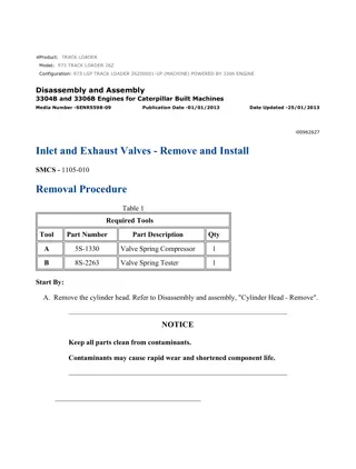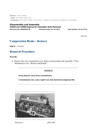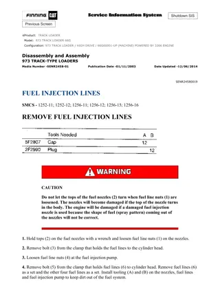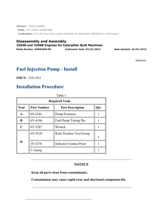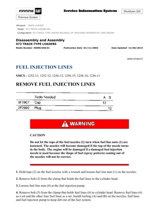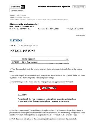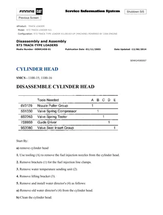
Caterpillar Cat 973 TRACK LOADER (Prefix 86G) Service Repair Manual Instant Download 9
Please open the website below to get the complete manualnn//
Download Presentation

Please find below an Image/Link to download the presentation.
The content on the website is provided AS IS for your information and personal use only. It may not be sold, licensed, or shared on other websites without obtaining consent from the author. Download presentation by click this link. If you encounter any issues during the download, it is possible that the publisher has removed the file from their server.
E N D
Presentation Transcript
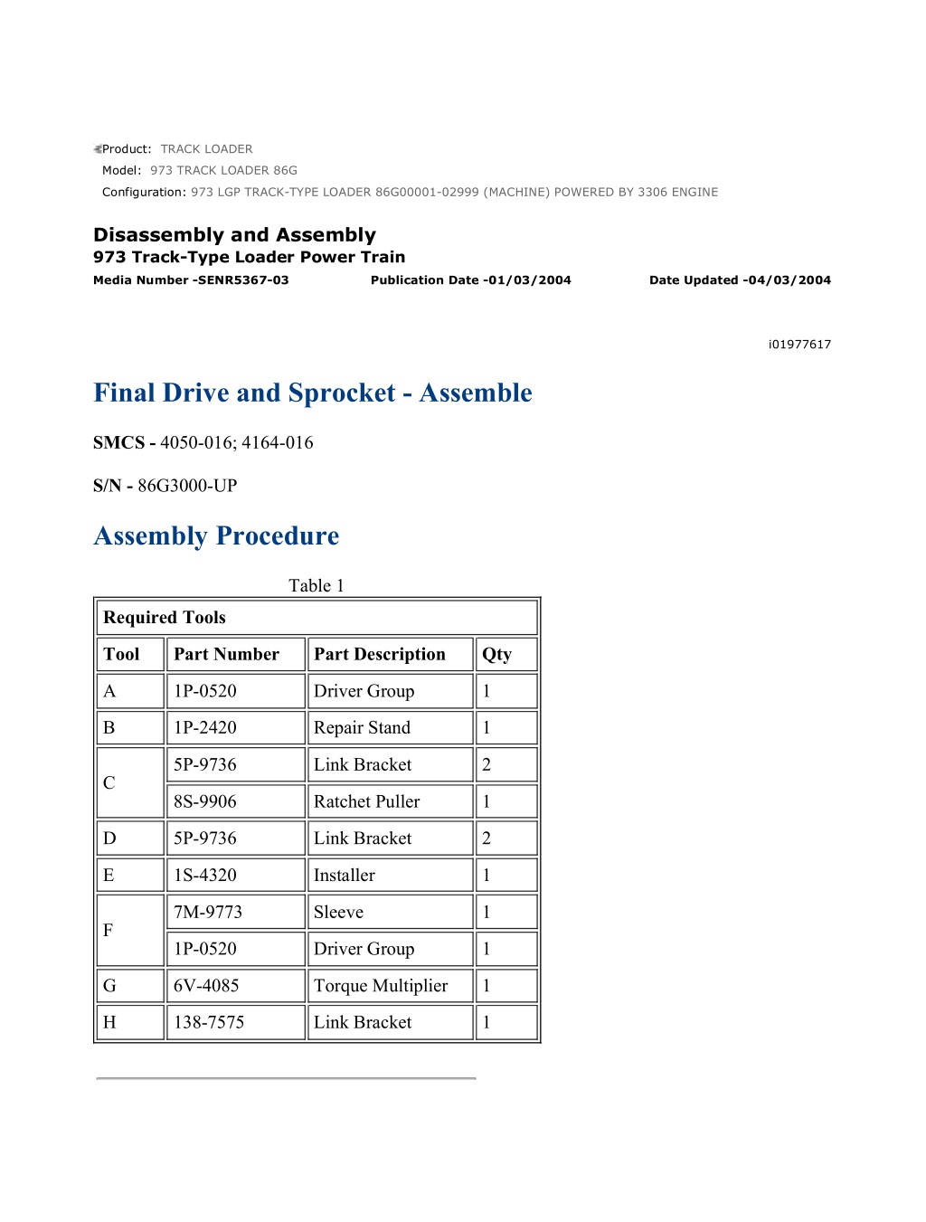
973 LGP TRACK-TYPE LOADER 86G00001-02999 (MACHINE) POWERED BY 3... 1/14 Product: TRACK LOADER Model: 973 TRACK LOADER 86G Configuration: 973 LGP TRACK-TYPE LOADER 86G00001-02999 (MACHINE) POWERED BY 3306 ENGINE Disassembly and Assembly 973 Track-Type Loader Power Train Media Number -SENR5367-03 Publication Date -01/03/2004 Date Updated -04/03/2004 i01977617 Final Drive and Sprocket - Assemble SMCS - 4050-016; 4164-016 S/N - 86G3000-UP Assembly Procedure Table 1 Required Tools Tool Part Number Part Description Qty A 1P-0520 Driver Group 1 B 1P-2420 Repair Stand 1 5P-9736 Link Bracket 2 C 8S-9906 Ratchet Puller 1 D 5P-9736 Link Bracket 2 E 1S-4320 Installer 1 7M-9773 Sleeve 1 F 1P-0520 Driver Group 1 G 6V-4085 Torque Multiplier 1 H 138-7575 Link Bracket 1 https://127.0.0.1/sisweb/sisweb/techdoc/techdoc_print_page.jsp?returnurl=/sis... 2021/11/20
973 LGP TRACK-TYPE LOADER 86G00001-02999 (MACHINE) POWERED BY 3... 2/14 Illustration 1 g00726420 Illustration 2 g00726422 1. Use Tooling (A) to install the bearing cup. Illustration 3 g00726423 2. Heat bearing cones (2) to a maximum temperature of 121 C (250 F). Do not heat the bearings longer than 8 hours. Install bearing cones (2) on the pinion. Use a suitable press to https://127.0.0.1/sisweb/sisweb/techdoc/techdoc_print_page.jsp?returnurl=/sis... 2021/11/20
973 LGP TRACK-TYPE LOADER 86G00001-02999 (MACHINE) POWERED BY 3... 3/14 position bearing cones (2) against the bearing cone seat after the bearing cones have become cool. Illustration 4 g00726424 3. Put clean oil on the bearing cones on pinion (3). Install pinion (3) in the final drive case. Illustration 5 g00726426 4. Install bearing cup (4) . https://127.0.0.1/sisweb/sisweb/techdoc/techdoc_print_page.jsp?returnurl=/sis... 2021/11/20
https://www.ebooklibonline.com Hello dear friend! Thank you very much for reading. Enter the link into your browser. The full manual is available for immediate download. https://www.ebooklibonline.com
973 LGP TRACK-TYPE LOADER 86G00001-02999 (MACHINE) POWERED BY 3... 4/14 Illustration 6 g00726427 5. Position retainer (5). Install three 3/8 - 16 inch bolts in the retainer in order to push the bearing cup far enough into the final drive case so that the correct bolts may be installed. Remove the 3/8 - 16 inch bolts and install the correct bolts in the retainer. Tighten the bolts and check that retainer (5) is tight against the final drive case. Illustration 7 g00726428 6. Check the pinion for end play. Measure the required torque that turns the pinion. If the end play is not more than 0.5 mm (0.02 inch), and the torque is 1.1 N m (10 lb in) or less, go to step 7. If the end play is more than 0.5 mm (0.02 inch), and retainer (5) is tight against the case, it will be necessary to install new parts. If the rotation torque is more than 1.1 N m (10 lb in), it will be necessary to install new parts. 7. Turn over the final drive case. Position the final drive case on Tooling (B). Use four bolts and nuts to hold the final drive case in position on Tooling (B). The weight of the final drive case is approximately 102 kg (225 lb). 8. Install thrust plate (6) with the oil grooves up using a brass bar and a hammer. https://127.0.0.1/sisweb/sisweb/techdoc/techdoc_print_page.jsp?returnurl=/sis... 2021/11/20
973 LGP TRACK-TYPE LOADER 86G00001-02999 (MACHINE) POWERED BY 3... 5/14 Illustration 8 g00726429 9. Heat bearing race and roller assembly (7) to a maximum temperature of 121 C (250 F). Do not heat the bearing longer than 8 hours. Install bearing race and roller assembly (7) on gear (8). The side of the bearing with the larger radius on the inside diameter must be toward the shoulder on the gear. After the bearing has become cool, use a press to push the bearing tightly against the seal. Put clean oil on the bearing. Illustration 9 g01025491 10. Use Tooling (C) to install gear (8) into the final drive case. The weight of gear (8) is approximately 52 kg (115 lb). https://127.0.0.1/sisweb/sisweb/techdoc/techdoc_print_page.jsp?returnurl=/sis... 2021/11/20
973 LGP TRACK-TYPE LOADER 86G00001-02999 (MACHINE) POWERED BY 3... 6/14 Illustration 10 g00726432 11. Lower the temperature of bearing race (9). Install bearing race (9) in the spindle. Install O- ring seal (10) on the spindle. Illustration 11 g01025492 12. Install guide bolts (12) in the final drive case. Fasten Tooling (D) and a suitable lifting device to spindle (11). Install spindle (11) on the final drive case. The weight of spindle (11) is approximately 129 kg (284 lb). Install the bolts that hold the spindle in place and tighten to a torque of 270 25 N m (200 18 lb ft). https://127.0.0.1/sisweb/sisweb/techdoc/techdoc_print_page.jsp?returnurl=/sis... 2021/11/20
973 LGP TRACK-TYPE LOADER 86G00001-02999 (MACHINE) POWERED BY 3... 7/14 Illustration 12 g00726434 13. Heat bearing cone (13) to a maximum temperature of 121 C (250 F). Do not heat the bearing longer than 8 hours. Install bearing cone (13) on the spindle. After the bearing cone has become cool, push the bearing cone tightly against the seat. To check that the bearing is against the seat, use a thickness gauge or look for an air gap. Put clean oil on the bearing cone. Illustration 13 g00726435 14. Use Tooling (E) in order to install Duo-cone seal (14) in the spindle. Note: The rubber seals and all surfaces that make contact with the seals must be clean and dry. After installation of the seals, put oil on the contact surfaces of the metal seals. Illustration 14 g00726436 15. Lower the temperature of bearing cups (15) and install the bearing cups in the hub. Use a thickness gauge to check that the bearing cups are against the seats. Use Tooling (E) to install the Duo-cone seal in the hub. https://127.0.0.1/sisweb/sisweb/techdoc/techdoc_print_page.jsp?returnurl=/sis... 2021/11/20
973 LGP TRACK-TYPE LOADER 86G00001-02999 (MACHINE) POWERED BY 3... 8/14 Illustration 15 g01025493 16. Install Tooling (D) and a suitable lifting device on the sprocket hub (16). Install the sprocket hub on the spindle. The weight of sprocket hub (16) is approximately 111 kg (245 lb). Illustration 16 g00726438 17. Use a suitable lifting device to secure hub (17) in position in ring gear (18). Install ring (19) that secures hub (17) in place in the ring gear. NOTICE Use new bolts in retainer (21) if the thread lock material is worn off the old bolts. https://127.0.0.1/sisweb/sisweb/techdoc/techdoc_print_page.jsp?returnurl=/sis... 2021/11/20
973 LGP TRACK-TYPE LOADER 86G00001-02999 (MACHINE) POWERED BY 3... 9/14 Illustration 17 g00726439 Illustration 18 g00726440 18. Heat bearing cone (20) to a maximum temperature of 121 C (250 F). Do not heat the bearing longer than 8 hours. Install bearing cone (20) on the spindle. Install ring gear and hub (17). Install plate (21). Install three bolts (22). Evenly tighten the three bolts (22) to a torque of 270 25 N m (200 18 lb ft). Install remaining bolts (22). Tighten bolts (22) to a torque of 270 25 N m (200 18 lb ft). Illustration 19 g00726441 https://127.0.0.1/sisweb/sisweb/techdoc/techdoc_print_page.jsp?returnurl=/sis... 2021/11/20
973 LGP TRACK-TYPE LOADER 86G00001-02999 (MACHINE) POWERED B... 10/14 19. Install planet shafts (23) in the planetary carrier. 20. Heat bearing cones (24) to a maximum temperature of 121 C (250 F). Do not heat the bearings longer than 8 hours. Install the lower bearing cones (24) on the planet shafts (23) . Illustration 20 g00726443 21. Lower the temperature of bearing cups (25). Install the bearing cups (25) in the planet gears. After the bearing cups are at room temperature, use Tooling (A) to check that the cups are against the seats. Illustration 21 g00726444 22. Install the planet gears (26) on the planet shafts. https://127.0.0.1/sisweb/sisweb/techdoc/techdoc_print_page.jsp?returnurl=/sis... 2021/11/20
973 LGP TRACK-TYPE LOADER 86G00001-02999 (MACHINE) POWERED B... 11/14 Illustration 22 g00726445 23. Heat bearing cones (27) to a maximum temperature of 121 C (250 F). Do not heat the bearing cones longer than 8 hours. Use Tooling (F) to check that the bearing cones are seated against the bearing cups. Illustration 23 g00726446 24. Position the plate on the planetary carrier. Install bolts (28) that hold the plate in position. Illustration 24 g00726447 https://127.0.0.1/sisweb/sisweb/techdoc/techdoc_print_page.jsp?returnurl=/sis... 2021/11/20
973 LGP TRACK-TYPE LOADER 86G00001-02999 (MACHINE) POWERED B... 12/14 25. Use Tooling (G) in order to tighten the bolts to a torque of 1125 100 N m (830 74 lb ft). Illustration 25 g01025496 26. Turn over the planetary carrier (29). Attach Tooling (D) and a suitable lifting device to planetary carrier (29). Position planetary carrier (29) on the sprocket hub. The weight of planetary carrier (29) is approximately 177 kg (390 lb). Install the bolts that secure planetary carrier (29) to the sprocket hub. Tighten the bolts to a torque of 270 25 N m (200 18 lb ft). Illustration 26 g01025498 27. Attach Tooling (H) and a suitable lifting device on sun gear (30). Install sun gear (30) in the planetary carrier. https://127.0.0.1/sisweb/sisweb/techdoc/techdoc_print_page.jsp?returnurl=/sis... 2021/11/20
973 LGP TRACK-TYPE LOADER 86G00001-02999 (MACHINE) POWERED B... 13/14 Illustration 27 g00726451 28. Install thrust button (31) in the cover. Illustration 28 g00726452 29. Check that the O-ring seal is in position on plug (32) and install the plug in the cover. Illustration 29 g00726453 https://127.0.0.1/sisweb/sisweb/techdoc/techdoc_print_page.jsp?returnurl=/sis... 2021/11/20
973 LGP TRACK-TYPE LOADER 86G00001-02999 (MACHINE) POWERED B... 14/14 30. Apply 7M-7260 Liquid Gasket Material on the contact surfaces of cover (33) and the planetary carrier. Position cover (33) on the planetary carrier. Apply 9S-3263 Thread Lock on the threads of the bolts that hold cover (33) in position and install the bolts. 31. Check that the drain plugs are in place. Fill the final drive. The capacity of the final drive is approximately 14 L (3.7 US gal). 32. Use a suitable lifting device in order to remove the final drive from Tooling (B). The weight of the final drive is approximately 839 kg (1850 lb). End By: a. Install track brakes. b. Install final drives and sprocket assemblies. https://127.0.0.1/sisweb/sisweb/techdoc/techdoc_print_page.jsp?returnurl=/sis... 2021/11/20
973 LGP TRACK-TYPE LOADER 86G00001-02999 (MACHINE) POWERED BY 3... 1/3 Product: TRACK LOADER Model: 973 TRACK LOADER 86G Configuration: 973 LGP TRACK-TYPE LOADER 86G00001-02999 (MACHINE) POWERED BY 3306 ENGINE Disassembly and Assembly 973 Track-Type Loader Power Train Media Number -SENR5367-03 Publication Date -01/03/2004 Date Updated -04/03/2004 i00980670 Final Drive and Sprocket - Install SMCS - 4050-012; 4164-012 S/N - 86G3000-UP Installation Procedure Table 1 Required Tools Tool Part Number Part Description Qty A 6V-2157 Link Bracket 1 1. Clean the old gasket material off the contact surfaces of the final drive case. Clean the old gasket material off surfaces of the frame. Put 7M-7260 Liquid Gasket Material on the contact surfaces. Illustration 1 g00725692 https://127.0.0.1/sisweb/sisweb/techdoc/techdoc_print_page.jsp?returnurl=/sis... 2021/11/20
973 LGP TRACK-TYPE LOADER 86G00001-02999 (MACHINE) POWERED BY 3... 2/3 2. Check that the O-ring seals (1) are in position on the drive shaft and the parking brake housing and that the O-ring seals (2) are in position on the final drive housing. Put clean oil on the O-ring seals. Remove the plug from the opening in the track motor. Illustration 2 g00725693 3. Install two 3/4" - 10 inch guide bolts (3) in the frame. Install Tool (A) and a hoist to the final drive. Position the final drive on the guide pins. Slide the final drive in place. The weight of the final drives and sprocket assemblies (4) is approximately 839 kg (1850 lb). Be careful not to damage the splines on the drive shaft for the final drives. 4. Install the bolts that hold the final drives in place. Tighten the bolts to a torque of 475 50 N m (350 37 lb ft). Illustration 3 g00725695 5. Install bolts (5) that hold the bottom of the final drive case to the frame. Tighten the bolts to a torque of 475 50 N m (350 37 lb ft). https://127.0.0.1/sisweb/sisweb/techdoc/techdoc_print_page.jsp?returnurl=/sis... 2021/11/20
973 LGP TRACK-TYPE LOADER 86G00001-02999 (MACHINE) POWERED BY 3... 3/3 Illustration 4 g00725696 6. Put sprocket segment (6) in position on the sprocket hub. Contact surfaces must be free of paint. Put 5P-3931 Anti-Seize Compound on the washer face and threads of the bolts and nuts for the sprocket segment. Install the bolts and the nuts (with the head of the bolt against the hub). Tighten the nuts to a torque of 300 55 N m (221 41 lb ft). To tighten the nuts, rotate 1/3 turn. A minimum torque of 570 N m (420 lb ft) is necessary after the 1/3 (120 degrees) turn. End By: a. Connect the track. Refer to Disassembly and Assembly, "Tracks - Connection". b. Remove the air from the track brakes. Refer to Testing and Adjusting, "Track Brakes - Air Removal". https://127.0.0.1/sisweb/sisweb/techdoc/techdoc_print_page.jsp?returnurl=/sis... 2021/11/20
973 LGP TRACK-TYPE LOADER 86G00001-02999 (MACHINE) POWERED BY 3... 1/5 Product: TRACK LOADER Model: 973 TRACK LOADER 86G Configuration: 973 LGP TRACK-TYPE LOADER 86G00001-02999 (MACHINE) POWERED BY 3306 ENGINE Disassembly and Assembly 973 Track-Type Loader Power Train Media Number -SENR5367-03 Publication Date -01/03/2004 Date Updated -04/03/2004 i00983810 Equalizer Bar - Remove and Install SMCS - 7206-010 S/N - 86G3000-UP Removal and Installation Procedure Table 1 Part Number Part Description A B 6V3009 Bar 4 5M6195 Bolt 8 2M849 Washer 40 6V3175 Hydraulic Puller 1 5P3100 Pump Group 1 6V86 Sleeve 1 9S5558 Stud 1 Remove the track roller frames. Refer to Disassembly and Assembly, "Track Roller Frames - Remove". Note: The equalizer bar can be removed without removing both track roller frames. However, at least one track roller frame must be removed before removing the equalizer bar. https://127.0.0.1/sisweb/sisweb/techdoc/techdoc_print_page.jsp?returnurl=/sis... 2021/11/20
973 LGP TRACK-TYPE LOADER 86G00001-02999 (MACHINE) POWERED BY 3... 2/5 Illustration 1 g00725175 1. Support both ends of equalizer bar (1) with hoists or a suitable lifting device. Illustration 2 g00725177 2. If only one track roller frame has been removed, remove the bolt and pin (2) from the remaining track roller frame. Illustration 3 g00725178 https://127.0.0.1/sisweb/sisweb/techdoc/techdoc_print_page.jsp?returnurl=/sis... 2021/11/20
973 LGP TRACK-TYPE LOADER 86G00001-02999 (MACHINE) POWERED BY 3... 3/5 Illustration 4 g00725179 3. Install Tooling (A) onto both sides of the equalizer bar and pads. Illustration 5 g00725180 4. Remove the bolt from pin (3) . 5. Use Tooling (B) to remove pin (3) . 6. Lower equalizer bar (1) to the floor. Equalizer bar (1) weighs 377 kg (831 lb). 7. Remove the equalizer bar (1) beneath the machine. https://127.0.0.1/sisweb/sisweb/techdoc/techdoc_print_page.jsp?returnurl=/sis... 2021/11/20
973 LGP TRACK-TYPE LOADER 86G00001-02999 (MACHINE) POWERED BY 3... 4/5 Illustration 6 g00725182 8. Check the condition of the bearings (4) and seals (5) in both ends of equalizer bar (1). If necessary, replace the bearings and the seals. Illustration 7 g00725183 9. Check the condition of seals (7) and bearings (6) in equalizer bar (1). If necessary, replace the seals and the bearings. 10. The following steps provide the procedure for installing the equalizer bar (1) . a. Reposition the equalizer bar (1) beneath the machine. Support the equalizer bar with hoists or suitable lifting devices. Note: Lubricate the pins and the bearings with 1P0808 Multipurpose Grease. b. Align bearings (6) and the hole for pin (3). Install the bolt and pin (3) . c. Reverse the procedures and steps 1 through 3. End By: Install the track roller frames. Refer to Disassembly and Assembly, "Track Roller Frames - Install". https://127.0.0.1/sisweb/sisweb/techdoc/techdoc_print_page.jsp?returnurl=/sis... 2021/11/20
973 LGP TRACK-TYPE LOADER 86G00001-02999 (MACHINE) POWERED BY 3... 1/2 Product: TRACK LOADER Model: 973 TRACK LOADER 86G Configuration: 973 LGP TRACK-TYPE LOADER 86G00001-02999 (MACHINE) POWERED BY 3306 ENGINE Disassembly and Assembly 973 Track-Type Loader Power Train Media Number -SENR5367-03 Publication Date -01/03/2004 Date Updated -04/03/2004 i00980490 Track Brake - Remove SMCS - 4251-011 S/N - 86G3000-UP Removal Procedure Start By: A. Remove final drives. Refer to Disassembly and Assembly, "Final Drives and Sprocket Assemblies - Remove". Illustration 1 g00725697 1. Disconnect oil lines (3) from housing (5) . 2. Remove bolts (1) and oil manifold (2) . 3. To release the tension on the springs in housing (5), loosen bolts (4) evenly. Remove bolts (4) and housing (5) . https://127.0.0.1/sisweb/sisweb/techdoc/techdoc_print_page.jsp?returnurl=/sis... 2021/11/20
973 LGP TRACK-TYPE LOADER 86G00001-02999 (MACHINE) POWERED BY 3... 2/2 Illustration 2 g00725698 4. Bend the ends of two short pieces of wire. Use the wires to remove discs (6) and plates (7) from ring (8) . 5. Remove ring (8) from the final drive case only if a replacement is necessary. https://127.0.0.1/sisweb/sisweb/techdoc/techdoc_print_page.jsp?returnurl=/sis... 2021/11/20
973 LGP TRACK-TYPE LOADER 86G00001-02999 (MACHINE) POWERED BY 3... 1/3 Product: TRACK LOADER Model: 973 TRACK LOADER 86G Configuration: 973 LGP TRACK-TYPE LOADER 86G00001-02999 (MACHINE) POWERED BY 3306 ENGINE Disassembly and Assembly 973 Track-Type Loader Power Train Media Number -SENR5367-03 Publication Date -01/03/2004 Date Updated -04/03/2004 i00980488 Track Brake - Disassemble SMCS - 4251-015 S/N - 86G3000-UP Disassembly Procedure Start By: A. Remove track brakes. Refer to Disassembly and Assembly, "Track Brakes - Removal". Illustration 1 g00725703 1. Put two bars (1) across the plate. Bars (1) are flat pieces of steel that are approximately 16.5 cm (6.5 inch) by 31.8 mm (1.25 inch) by 6.4 mm (0.25 inch). Put ring (2) over the bars and install two bolts (3) through ring (2) and the housing. Install the washers and install the nuts on the bolts. Bolts (3) are 5 inches long. Tighten bolts (3). Position the springs in the track brake. Use a soft hammer to push piston (4) through the plate so ring (5) can be removed. Use Tool (A) to remove ring (5) from the piston. https://127.0.0.1/sisweb/sisweb/techdoc/techdoc_print_page.jsp?returnurl=/sis... 2021/11/20
973 LGP TRACK-TYPE LOADER 86G00001-02999 (MACHINE) POWERED BY 3... 2/3 2. To release the tension in the springs in the track brake, loosen bolts (3) evenly. 3. Remove bolts (3) from the track brake housing. Remove ring (2) from the track brake housing. Remove bars (1) from the track brake housing. Remove plate (6) from the track brake housing. Illustration 2 g00725705 4. Remove two springs (7) from the track brake housing. Illustration 3 g00725706 5. Use a soft hammer to push piston (4) out of the track brake housing. 6. Remove O-ring seal (8) from the parking brake housing. https://127.0.0.1/sisweb/sisweb/techdoc/techdoc_print_page.jsp?returnurl=/sis... 2021/11/20
973 LGP TRACK-TYPE LOADER 86G00001-02999 (MACHINE) POWERED BY 3... 3/3 Illustration 4 g00725707 7. Remove seal assemblies (9) and (10) from the piston. https://127.0.0.1/sisweb/sisweb/techdoc/techdoc_print_page.jsp?returnurl=/sis... 2021/11/20
973 LGP TRACK-TYPE LOADER 86G00001-02999 (MACHINE) POWERED BY 3... 1/3 Product: TRACK LOADER Model: 973 TRACK LOADER 86G Configuration: 973 LGP TRACK-TYPE LOADER 86G00001-02999 (MACHINE) POWERED BY 3306 ENGINE Disassembly and Assembly 973 Track-Type Loader Power Train Media Number -SENR5367-03 Publication Date -01/03/2004 Date Updated -04/03/2004 i00980487 Track Brake - Assemble SMCS - 4251-016 S/N - 86G3000-UP Assembly Procedure Table 1 Required Tools Tool Part Number Part Description Qty A 2P-8312 External Retaining Ring Pliers 1 Note: Put clean oil on all parts before assembly. Illustration 1 g00725708 1. Install seals (1) and (2) on the piston. https://127.0.0.1/sisweb/sisweb/techdoc/techdoc_print_page.jsp?returnurl=/sis... 2021/11/20
Suggest: If the above button click is invalid. Please download this document first, and then click the above link to download the complete manual. Thank you so much for reading
973 LGP TRACK-TYPE LOADER 86G00001-02999 (MACHINE) POWERED BY 3... 2/3 Illustration 2 g00725709 2. Install piston (3) in the track brake housing. 3. Install O-ring seal (4) on the track brake housing. Illustration 3 g00725710 4. Install springs (5) in the track brake housing. https://127.0.0.1/sisweb/sisweb/techdoc/techdoc_print_page.jsp?returnurl=/sis... 2021/11/20
https://www.ebooklibonline.com Hello dear friend! Thank you very much for reading. Enter the link into your browser. The full manual is available for immediate download. https://www.ebooklibonline.com


