Caterpillar Cat 966F II Wheel Loader (Prefix 9YJ) Service Repair Manual Instant Download (9YJ00001 and up)
Please open the website below to get the complete manualnn//
Download Presentation

Please find below an Image/Link to download the presentation.
The content on the website is provided AS IS for your information and personal use only. It may not be sold, licensed, or shared on other websites without obtaining consent from the author. Download presentation by click this link. If you encounter any issues during the download, it is possible that the publisher has removed the file from their server.
E N D
Presentation Transcript
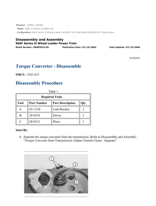
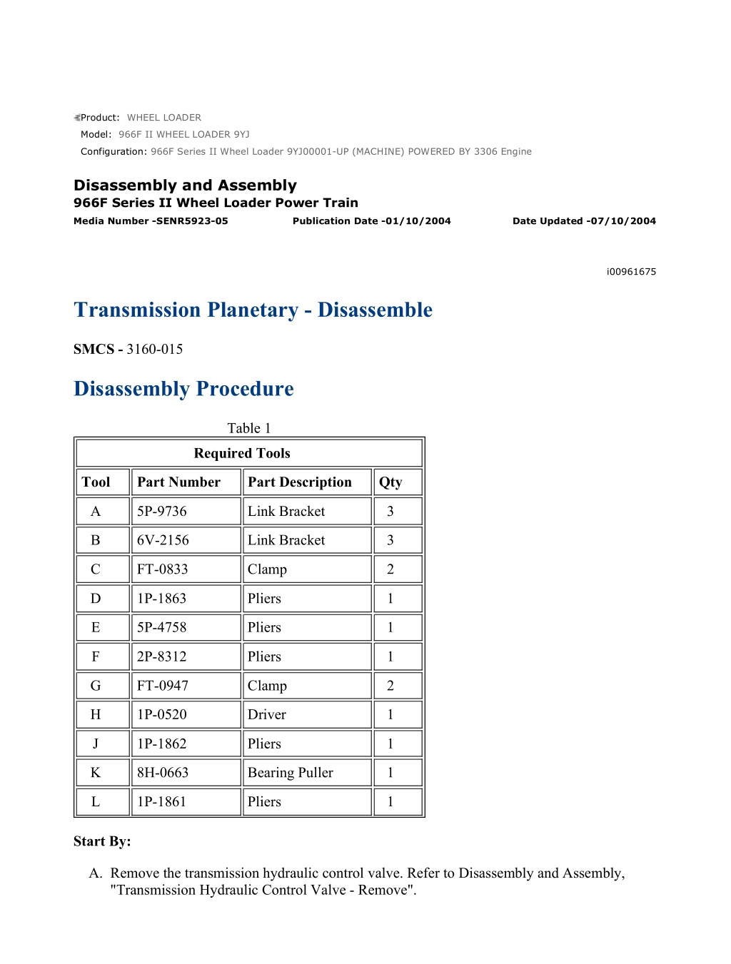
966F Series II Wheel Loader 9YJ00001-UP (MACHINE) POWERED BY 3306 Engin... 1/27 Product: WHEEL LOADER Model: 966F II WHEEL LOADER 9YJ Configuration: 966F Series II Wheel Loader 9YJ00001-UP (MACHINE) POWERED BY 3306 Engine Disassembly and Assembly 966F Series II Wheel Loader Power Train Media Number -SENR5923-05 Publication Date -01/10/2004 Date Updated -07/10/2004 i00961675 Transmission Planetary - Disassemble SMCS - 3160-015 Disassembly Procedure Table 1 Required Tools Tool Part Number Part Description Qty A 5P-9736 Link Bracket 3 B 6V-2156 Link Bracket 3 C FT-0833 Clamp 2 D 1P-1863 Pliers 1 E 5P-4758 Pliers 1 F 2P-8312 Pliers 1 G FT-0947 Clamp 2 H 1P-0520 Driver 1 J 1P-1862 Pliers 1 K 8H-0663 Bearing Puller 1 L 1P-1861 Pliers 1 Start By: A. Remove the transmission hydraulic control valve. Refer to Disassembly and Assembly, "Transmission Hydraulic Control Valve - Remove". https://127.0.0.1/sisweb/sisweb/techdoc/techdoc_print_page.jsp?returnurl=/sisw... 2022/5/8
966F Series II Wheel Loader 9YJ00001-UP (MACHINE) POWERED BY 3306 Engin... 2/27 B. Separate the torque converter from the transmission. Refer to Disassembly and Assembly, "Torque Converter from Transmission, Output Transfer Gears - Separate". C. Separate the transmission from the output transfer gears. Refer to Disassembly and Assembly, "Transmission from Output Transfer Gears - Separate". Note: Cleanliness is an important factor. Before the disassembly procedure, the exterior of the component should be thoroughly cleaned. This will help to prevent dirt from entering the internal mechanism. Illustration 1 g00490174 1. Fasten Tooling (A) and a hoist to case (1), as shown. Remove the bolts that hold case (1) to the manifold. Use two 3/8" - 16 NC forcing screws to separate case (1) from the manifold. Remove case (1) from the transmission. The weight of the case is 91 kg (200 lb). Illustration 2 g00490206 2. Remove elbow (5) and the O-ring seal from the reverse clutch housing. 3. Remove the bolt, retainer (6) and gear (7) from the transmission input shaft. https://127.0.0.1/sisweb/sisweb/techdoc/techdoc_print_page.jsp?returnurl=/sisw... 2022/5/8
966F Series II Wheel Loader 9YJ00001-UP (MACHINE) POWERED BY 3306 Engin... 3/27 Illustration 3 g00490222 4. Use a hoist to turn the transmission, as shown. The weight of the transmission is 453 kg (1000 lb). 5. Remove O-ring seal (10) and two O-ring seals (9) . Note: Put alignment marks across the clutch housings for assembly purposes. Illustration 4 g00490238 6. Install Tooling (C) in order to hold the piston in the No. 6 clutch housing (11) . 7. Fasten Tooling (B) and a hoist to clutch housing (11). Remove bolts (8). Remove clutch housing (11) from the transmission. The weight of the clutch housing is 27 kg (60 lb). https://127.0.0.1/sisweb/sisweb/techdoc/techdoc_print_page.jsp?returnurl=/sisw... 2022/5/8
https://www.ebooklibonline.com Hello dear friend! Thank you very much for reading. Enter the link into your browser. The full manual is available for immediate download. https://www.ebooklibonline.com
966F Series II Wheel Loader 9YJ00001-UP (MACHINE) POWERED BY 3306 Engin... 4/27 Illustration 5 g00490267 8. Remove clutch piston (12) from clutch housing (11). Remove the seal rings from the clutch piston. Illustration 6 g00490270 9. Remove reaction dowels (14), springs (15), three friction discs (13) and the two clutch plates from the manifold. Illustration 7 g00490271 https://127.0.0.1/sisweb/sisweb/techdoc/techdoc_print_page.jsp?returnurl=/sisw... 2022/5/8
966F Series II Wheel Loader 9YJ00001-UP (MACHINE) POWERED BY 3306 Engin... 5/27 10. Remove ring gear (16) from the carrier. Illustration 8 g00490275 11. Use Tooling (D) to remove retaining ring (17) from the transmission shaft. Illustration 9 g00490277 12. Remove carrier assembly (18) from the manifold. https://127.0.0.1/sisweb/sisweb/techdoc/techdoc_print_page.jsp?returnurl=/sisw... 2022/5/8
966F Series II Wheel Loader 9YJ00001-UP (MACHINE) POWERED BY 3306 Engin... 6/27 Illustration 10 g00490287 13. Disassemble carrier assembly (18) by the following steps: a. Remove the ring seal from the outside of the carrier assembly. b. Use a hammer and a punch to push the spring pin through carrier (18) into planetary shaft (19). Remove planetary shaft (19) from carrier (18) . Illustration 11 g00490289 c. Remove thrust discs (20) and (24), bearings (21) and (23) and planetary gear (22) . d. Repeat steps 13.b through 13.c for the removal of the other two planetary gears. https://127.0.0.1/sisweb/sisweb/techdoc/techdoc_print_page.jsp?returnurl=/sisw... 2022/5/8
966F Series II Wheel Loader 9YJ00001-UP (MACHINE) POWERED BY 3306 Engin... 7/27 Illustration 12 g00490302 14. Remove retaining ring (25) and sun gear (26) from the output shaft. 15. Use Tooling (D) to remove retaining ring (27) from the housing. Illustration 13 g00490365 16. Fasten Tooling (B) and a hoist to manifold assembly (28), as shown. Remove manifold assembly (28) from the transmission. The weight of the manifold assembly is 64 kg (140 lb). Remove the large O-ring seal from the manifold assembly. https://127.0.0.1/sisweb/sisweb/techdoc/techdoc_print_page.jsp?returnurl=/sisw... 2022/5/8
966F Series II Wheel Loader 9YJ00001-UP (MACHINE) POWERED BY 3306 Engin... 8/27 Illustration 14 g00490374 17. Use Tooling (E) to remove retaining ring (29) from the manifold. Remove bearing (30) from the manifold. Illustration 15 g00490379 18. Remove clutch springs (32), two friction discs (31) and one clutch plate from the No. 3 and No. 4 clutch housing. Illustration 16 g00490383 19. Remove retaining ring (33) and housing assembly (34) from the ring gear for the No. 4 clutch. https://127.0.0.1/sisweb/sisweb/techdoc/techdoc_print_page.jsp?returnurl=/sisw... 2022/5/8
966F Series II Wheel Loader 9YJ00001-UP (MACHINE) POWERED BY 3306 Engin... 9/27 Illustration 17 g00490387 20. Remove seal rings (36) from ring carrier (35) . 21. Check the condition of ring carrier (35). If ring carrier (35) is worn or damaged, use new parts for replacement. If ring carrier (35) is not worn or damaged, do not remove the ring carrier. Use a hammer and a chisel in order to replace ring carrier (35). Remove the ring carrier and the pin that holds the ring carrier in position on housing (34) . Illustration 18 g00490393 22. Use steel spacers and a press to push retainer plate (38). Put three disc springs (40) under compression. Note: Mark the location of three disc springs (40) for assembly purposes. 23. Use Tooling (F) to remove retaining ring (39) from housing (34). Release the pressure on plate (38). Remove the retainer plate, three disc springs (40) and No. 5 piston (37) from housing (34) . 24. Remove the two seal rings from piston (37) . https://127.0.0.1/sisweb/sisweb/techdoc/techdoc_print_page.jsp?returnurl=/sisw... 2022/5/8
966F Series II Wheel Loader 9YJ00001-UP (MACHINE) POWERED BY 3306 En... 10/27 Illustration 19 g00490423 25. Remove ring gear (42) from the No. 3 and No. 4 clutch housing. Remove three friction discs (41) and two clutch plates from ring gear (42). Remove the clutch plate from the ring gear. Illustration 20 g00490427 26. Remove No. 4 clutch piston (43) from the clutch housing. Remove reaction dowels (44) from the clutch housing. Illustration 21 g00490431 https://127.0.0.1/sisweb/sisweb/techdoc/techdoc_print_page.jsp?returnurl=/sisw... 2022/5/8
966F Series II Wheel Loader 9YJ00001-UP (MACHINE) POWERED BY 3306 En... 11/27 27. Remove seal rings (45) and (46) from clutch piston (43) . Illustration 22 g00490483 28. Install Tooling (G) in order to hold No. 3 clutch piston in clutch housing (47). Install two 5/8" - 11 NC forged eyebolts in clutch housing (47), as shown. Fasten a hoist to the eyebolts. Remove clutch housing (47) and the clutch piston. The weight of the unit is 41 kg (90 lb). Illustration 23 g00490484 29. Remove clutch piston (48) from clutch housing (47). Remove the seal rings from clutch piston (48) . https://127.0.0.1/sisweb/sisweb/techdoc/techdoc_print_page.jsp?returnurl=/sisw... 2022/5/8
966F Series II Wheel Loader 9YJ00001-UP (MACHINE) POWERED BY 3306 En... 12/27 Illustration 24 g00491248 30. Remove springs (49), three friction discs (50) and the two clutch plates from the No. 2 clutch housing. Illustration 25 g00491257 31. Use Tooling (D) to remove retaining ring (52). Remove clutch hub (51) . Illustration 26 g00491295 https://127.0.0.1/sisweb/sisweb/techdoc/techdoc_print_page.jsp?returnurl=/sisw... 2022/5/8
966F Series II Wheel Loader 9YJ00001-UP (MACHINE) POWERED BY 3306 En... 13/27 32. Remove sun gear (53), carrier assembly (54) and ring gear (55) from the transmission shaft as a unit. 33. Remove sun gear (53) from carrier assembly (54) . 34. Disassemble carrier assembly (54) by the following steps: Illustration 27 g00491296 a. Put the lock ring under compression. Remove carrier assembly (54) from ring gear (55). Several short lengths of 3.175 mm (.125 inch) rod (56) with a point ground on one end can be used to put the ring under compression. Illustration 28 g00491322 b. Use a hammer and a punch to push the spring pin through carrier (54) into planetary shaft (57). Remove planetary shaft (57) from carrier (54) . https://127.0.0.1/sisweb/sisweb/techdoc/techdoc_print_page.jsp?returnurl=/sisw... 2022/5/8
966F Series II Wheel Loader 9YJ00001-UP (MACHINE) POWERED BY 3306 En... 14/27 Illustration 29 g00491323 c. Remove thrust discs (58) and (61), bearing (60) and planetary gear (59) from carrier (54) . d. Repeat steps 34.b through 34.c for the removal of the other two planetary gears. Illustration 30 g00491381 e. Remove retaining ring (62) that holds bearing (63) in carrier (54) . Illustration 31 g00491429 https://127.0.0.1/sisweb/sisweb/techdoc/techdoc_print_page.jsp?returnurl=/sisw... 2022/5/8
966F Series II Wheel Loader 9YJ00001-UP (MACHINE) POWERED BY 3306 En... 15/27 f. Use Tooling (H) and a press to push bearing (63) out of carrier (54) . Illustration 32 g00491433 35. Install Tooling (C) in order to hold the forward clutch piston in the clutch housing. 36. Fasten Tooling (B) and a hoist to the No. 2 clutch housing. Remove the bolts and the clutch housing with the clutch piston. The weight of the unit is 27 kg (60 lb). Illustration 33 g00491437 37. Remove clutch piston (64) from the No. 2 clutch housing (65). Remove the seal rings from clutch piston (64) . https://127.0.0.1/sisweb/sisweb/techdoc/techdoc_print_page.jsp?returnurl=/sisw... 2022/5/8
966F Series II Wheel Loader 9YJ00001-UP (MACHINE) POWERED BY 3306 En... 16/27 Illustration 34 g00491460 38. Remove springs (68) and reaction dowels (67) . 39. Remove three friction discs (66) and the two clutch plates. Illustration 35 g00491463 40. Remove ring gear (69) from the carrier assembly and the shaft. Illustration 36 g00491464 https://127.0.0.1/sisweb/sisweb/techdoc/techdoc_print_page.jsp?returnurl=/sisw... 2022/5/8
966F Series II Wheel Loader 9YJ00001-UP (MACHINE) POWERED BY 3306 En... 17/27 41. Remove retaining ring (71) that holds the bearing in the carrier assembly. Remove shaft (70) from the carrier assembly and the inner shaft. Illustration 37 g00491465 42. Use Tooling (D) to remove retaining ring (73) from the end of shaft (70). Remove gear (72) from shaft (70) . Illustration 38 g00491466 43. Use Tooling (H) and a press to push shaft (70) out of bearing (74), as shown. https://127.0.0.1/sisweb/sisweb/techdoc/techdoc_print_page.jsp?returnurl=/sisw... 2022/5/8
966F Series II Wheel Loader 9YJ00001-UP (MACHINE) POWERED BY 3306 En... 18/27 Illustration 39 g00491467 Illustration 40 g00491468 44. Remove bearings (75) and (76) from the ends of shaft (70) . Illustration 41 g00491470 45. Remove plate assembly (77) from the reverse clutch housing. https://127.0.0.1/sisweb/sisweb/techdoc/techdoc_print_page.jsp?returnurl=/sisw... 2022/5/8
Suggest: For more complete manuals. Please go to the home page. https://www.ebooklibonline.com If the above button click is invalid. Please download this document first, and then click the above link to download the complete manual. Thank you so much for reading
966F Series II Wheel Loader 9YJ00001-UP (MACHINE) POWERED BY 3306 En... 19/27 Illustration 42 g00491483 46. Use Tooling (J) to remove retaining ring (79) that holds sun gear (78) . Illustration 43 g00491484 47. Remove carrier assembly (80) and ring gear (81) . 48. Disassemble carrier assembly (80) by the following steps: Illustration 44 g00491836 https://127.0.0.1/sisweb/sisweb/techdoc/techdoc_print_page.jsp?returnurl=/sisw... 2022/5/8
966F Series II Wheel Loader 9YJ00001-UP (MACHINE) POWERED BY 3306 En... 20/27 a. Remove the sun gear from carrier assembly (80) . b. Remove seal ring (82) from carrier assembly (80) . Illustration 45 g00491842 c. Compress the retaining ring. Remove carrier assembly (80) from ring gear (81). Several short lengths of 3.175 mm (.125 inch) rod (56) with a point ground on one end can be used to put the retaining ring under compression. Illustration 46 g00491844 d. Use a hammer and a punch to push the spring pins through carrier assembly (80) and into planetary shafts (84). Remove planetary shafts (84) from carrier assembly (80) . https://127.0.0.1/sisweb/sisweb/techdoc/techdoc_print_page.jsp?returnurl=/sisw... 2022/5/8
https://www.ebooklibonline.com Hello dear friend! Thank you very much for reading. Enter the link into your browser. The full manual is available for immediate download. https://www.ebooklibonline.com

