Caterpillar Cat 955L TRACK LOADER (Prefix 64J) Service Repair Manual Instant Download (64J07632 and up)
Please open the website below to get the complete manualnn//
Download Presentation

Please find below an Image/Link to download the presentation.
The content on the website is provided AS IS for your information and personal use only. It may not be sold, licensed, or shared on other websites without obtaining consent from the author. Download presentation by click this link. If you encounter any issues during the download, it is possible that the publisher has removed the file from their server.
E N D
Presentation Transcript
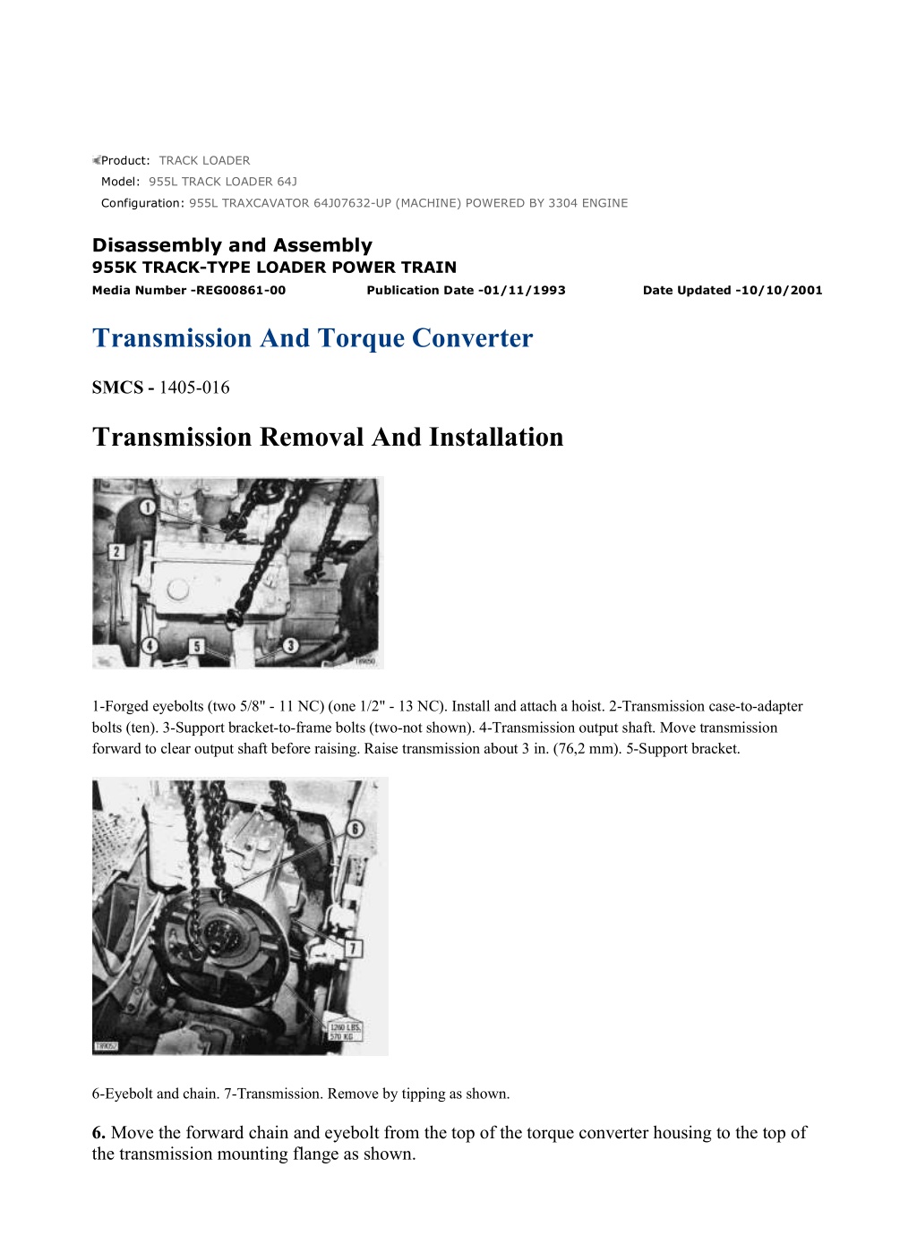
955L TRAXCAVATOR 64J07632-UP (MACHINE) POWERED BY 3304 ENGINE(... 1/10 Product: TRACK LOADER Model: 955L TRACK LOADER 64J Configuration: 955L TRAXCAVATOR 64J07632-UP (MACHINE) POWERED BY 3304 ENGINE Disassembly and Assembly 955K TRACK-TYPE LOADER POWER TRAIN Media Number -REG00861-00 Publication Date -01/11/1993 Date Updated -10/10/2001 Transmission And Torque Converter SMCS - 1405-016 Transmission Removal And Installation 1-Forged eyebolts (two 5/8" - 11 NC) (one 1/2" - 13 NC). Install and attach a hoist. 2-Transmission case-to-adapter bolts (ten). 3-Support bracket-to-frame bolts (two-not shown). 4-Transmission output shaft. Move transmission forward to clear output shaft before raising. Raise transmission about 3 in. (76,2 mm). 5-Support bracket. 6-Eyebolt and chain. 7-Transmission. Remove by tipping as shown. 6. Move the forward chain and eyebolt from the top of the torque converter housing to the top of the transmission mounting flange as shown. https://127.0.0.1/sisweb/sisweb/techdoc/techdoc_print_page.jsp?returnurl=/sis... 2021/12/14
955L TRAXCAVATOR 64J07632-UP (MACHINE) POWERED BY 3304 ENGINE(... 2/10 Removing Transmission From Case 1. Position the transmission vertically on a suitable stand or blocks. 2, 3, 4, 5-Bolts. Do not remove. 6-Bolts (two). Replace with 5/8" - 11 NC forged eyebolts. 7-Bolts (six). 8-Planetary transmission. Remove from transmission case and position vertically on blocks. Transmission Disassembly https://127.0.0.1/sisweb/sisweb/techdoc/techdoc_print_page.jsp?returnurl=/sis... 2021/12/14
955L TRAXCAVATOR 64J07632-UP (MACHINE) POWERED BY 3304 ENGINE(... 3/10 This is a cross section of the planetary transmission. The shaded areas, in order of removal, are: A-No. 1 clutch, clutch housing and planet carrier. B-No. 2 clutch, clutch housing, ring gear and No. 1 ring gear. C-No. 3 clutch, clutch housing and ring gear, No. 1 and No. 2 sun gear, No. 2, No. 3 and No. 4 planet carrier. D-No. 4 clutch, clutch housing and ring gear. E-No. 5 clutch and ring gear. F-No. 5 clutch housing, No. 3, No. 4 and No. 5 sun gears, output shaft. A - No. 1 Clutch, Clutch Housing and Planet Carrier 1. Remove only the three bolts located by the "S" mark. When installing tighten to a torque of 85 5 lb. ft. (11,8 0,7 mkg). https://127.0.0.1/sisweb/sisweb/techdoc/techdoc_print_page.jsp?returnurl=/sis... 2021/12/14
https://www.ebooklibonline.com Hello dear friend! Thank you very much for reading. Enter the link into your browser. The full manual is available for immediate download. https://www.ebooklibonline.com
955L TRAXCAVATOR 64J07632-UP (MACHINE) POWERED BY 3304 ENGINE(... 4/10 2-No. 1 clutch housing. Invert, remove the two 3/8" bolts and disassemble as shown. The exploded view is shown inverted. B - No. 2 Clutch, Clutch Housing, Ring Gear and No. 1 Ring Gear https://127.0.0.1/sisweb/sisweb/techdoc/techdoc_print_page.jsp?returnurl=/sis... 2021/12/14
955L TRAXCAVATOR 64J07632-UP (MACHINE) POWERED BY 3304 ENGINE(... 5/10 1-Pins (two). Drive flush with face of carrier to allow retaining ring removal. C-No. 3 Clutch, Clutch Housing and Ring Gear, No. 1 and No. 2 Sun Gear, No. 2, No. 3 and No. 4 Planet Carrier 1-Remove bolt and retainer from inside of sun gear. Then remove sun gear and install 3/8" - 16 NC forged eyebolt as shown. 2-Clutch release springs (ten). 3-Clutch reaction pins (five). https://127.0.0.1/sisweb/sisweb/techdoc/techdoc_print_page.jsp?returnurl=/sis... 2021/12/14
955L TRAXCAVATOR 64J07632-UP (MACHINE) POWERED BY 3304 ENGINE(... 6/10 D-No. 4 Clutch, Clutch Housing and Ring Gear 1-Pins (two). Drive flush with face of carrier to allow retaining ring removal. E-No. 5 Clutch and Ring Gear https://127.0.0.1/sisweb/sisweb/techdoc/techdoc_print_page.jsp?returnurl=/sis... 2021/12/14
955L TRAXCAVATOR 64J07632-UP (MACHINE) POWERED BY 3304 ENGINE(... 7/10 F-No. 5 Clutch Housing, No. 3, No. 4 and No. 5 Sun Gears and Output Shaft 1-Retaining ring. Must be removed first to allow output shaft to be lowered for removal of retaining ring at other end of shaft. Torque Converter Removal And Installation 1. Place transmission and torque converter unit on a suitable stand as shown. https://127.0.0.1/sisweb/sisweb/techdoc/techdoc_print_page.jsp?returnurl=/sis... 2021/12/14
955L TRAXCAVATOR 64J07632-UP (MACHINE) POWERED BY 3304 ENGINE(... 8/10 2-Bolts (two). Replace two diametrically opposite bolts with 3/8" - 16 NC forged eyebolts. 3-Bolts (fourteen). 4-Torque converter oil supply tube. 5-Guide pins (two). With torque converter in position shown, remove two retaining bolts and replace with 1/2" - 13 NC guide pins. 6-Bolts (five). 7-Retainer. 8-Output shaft. 9-Cover. https://127.0.0.1/sisweb/sisweb/techdoc/techdoc_print_page.jsp?returnurl=/sis... 2021/12/14
955L TRAXCAVATOR 64J07632-UP (MACHINE) POWERED BY 3304 ENGINE(... 9/10 5-Guide pins (two). 10-Forged eyebolt. Install 1/4" - 20 NC forged eyebolt and attach a hoist. Torque Converter Disassembly https://127.0.0.1/sisweb/sisweb/techdoc/techdoc_print_page.jsp?returnurl=/sis... 2021/12/14
955L TRAXCAVATOR 64J07632-UP (MACHINE) POWERED BY 3304 ENGIN... 10/10 7, 26 Use an 8B7548 Push Puller, 8H663 Bearing Pulling Attachment and a S2398 Spacer to remove bearings. https://127.0.0.1/sisweb/sisweb/techdoc/techdoc_print_page.jsp?returnurl=/sis... 2021/12/14
955L TRAXCAVATOR 64J07632-UP (MACHINE) POWERED BY 3304 ENGINE(... 1/3 Product: TRACK LOADER Model: 955L TRACK LOADER 64J Configuration: 955L TRAXCAVATOR 64J07632-UP (MACHINE) POWERED BY 3304 ENGINE Disassembly and Assembly 955K TRACK-TYPE LOADER POWER TRAIN Media Number -REG00861-00 Publication Date -01/11/1993 Date Updated -10/10/2001 Transmission Hydraulic Controls SMCS - 1405-016 Transmission Hydraulic Control Removal And Installation 1-Lever. 2-Lever. 3-Cover. 4-Clip. 5-Tube. Push into housing until clear of valve body. 6-Twelve-point head bolts (sixteen). 7-Six-point head bolts (five). Transmission Hydraulic Control Disassembly https://127.0.0.1/sisweb/sisweb/techdoc/techdoc_print_page.jsp?returnurl=/sis... 2021/12/14
955L TRAXCAVATOR 64J07632-UP (MACHINE) POWERED BY 3304 ENGINE(... 2/3 Transmission Mechanical Control Linkage And Column 1-Grab iron assembly. 2-Knob. 3-Governor control linkage. 4-Bolts (six). 5-Column assembly. 6-Speed selector control rod. 7-Directional control rod. 8-Bracket. 9-Bolts (four). 10-Transmission control linkage. https://127.0.0.1/sisweb/sisweb/techdoc/techdoc_print_page.jsp?returnurl=/sis... 2021/12/14
955L TRAXCAVATOR 64J07632-UP (MACHINE) POWERED BY 3304 ENGINE(... 3/3 https://127.0.0.1/sisweb/sisweb/techdoc/techdoc_print_page.jsp?returnurl=/sis... 2021/12/14
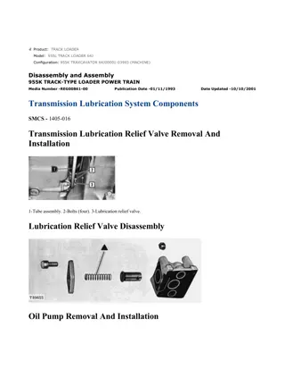
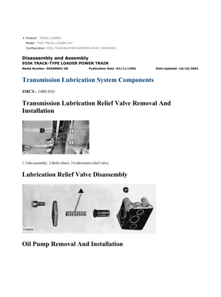
955L TRAXCAVATOR 64J07632-UP (MACHINE) POWERED BY 3304 ENGINE(... 1/3 Product: TRACK LOADER Model: 955L TRACK LOADER 64J Configuration: 955L TRAXCAVATOR 64J07632-UP (MACHINE) POWERED BY 3304 ENGINE Disassembly and Assembly 955K TRACK-TYPE LOADER POWER TRAIN Media Number -REG00861-00 Publication Date -01/11/1993 Date Updated -10/10/2001 Transmission Lubrication System Components SMCS - 1405-016 Transmission Lubrication Relief Valve Removal And Installation 1-Tube assembly. 2-Bolts (four). 3-Lubrication relief valve. Lubrication Relief Valve Disassembly Oil Pump Removal And Installation https://127.0.0.1/sisweb/sisweb/techdoc/techdoc_print_page.jsp?returnurl=/sis... 2021/12/14
955L TRAXCAVATOR 64J07632-UP (MACHINE) POWERED BY 3304 ENGINE(... 2/3 1-Bolts (two). 2-Transmission oil pump. Oil Pump Disassembly 3, 6 Install bearings with joints at (A and B) as shown. Install bearings .062 in. (1,575 mm) below the inner surfaces of the cover and base. 4 Pump drive gear must rotate freely by hand. Transmission Oil Filter And Screen Removal And Installation 1-Bolts (two). 2-Oil pump supply tube and O-ring seal. https://127.0.0.1/sisweb/sisweb/techdoc/techdoc_print_page.jsp?returnurl=/sis... 2021/12/14
955L TRAXCAVATOR 64J07632-UP (MACHINE) POWERED BY 3304 ENGINE(... 3/3 3-Nuts (five). 4-Filter and screen group with O-ring seals. Transmission Oil Filter And Screen Disassembly https://127.0.0.1/sisweb/sisweb/techdoc/techdoc_print_page.jsp?returnurl=/sis... 2021/12/14
955L TRAXCAVATOR 64J07632-UP (MACHINE) POWERED BY 3304 ENGINE(... 1/2 Product: TRACK LOADER Model: 955L TRACK LOADER 64J Configuration: 955L TRAXCAVATOR 64J07632-UP (MACHINE) POWERED BY 3304 ENGINE Disassembly and Assembly 955K TRACK-TYPE LOADER POWER TRAIN Media Number -REG00861-00 Publication Date -01/11/1993 Date Updated -10/10/2001 Bevel Pinion SMCS - 1405-016 Transmission Mounting Adapter Removal And Installation 1-Forged eyebolt (1/2"-13 NC) and nut. Install eyebolt and nut and attach a hoist. 2-Bolts (eleven). 3-Seal. Transmission Mounting Adapter Disassembly https://127.0.0.1/sisweb/sisweb/techdoc/techdoc_print_page.jsp?returnurl=/sis... 2021/12/14
955L TRAXCAVATOR 64J07632-UP (MACHINE) POWERED BY 3304 ENGINE(... 2/2 Bevel Pinion, Bearing Cage And Pinion Locating Shims Removal And Installation 1-Bolts (four). 2-Bevel pinion bearing cage and bevel pinion. 3-Bevel pinion locating shims. NOTE: If the bevel gear location is changed or if a new bearing cage or pinion is installed, the pinion location must be checked. See BEVEL GEAR AND PINION SETTING. Bevel Pinion And Bearing Disassembly 1 Press spacer onto bevel pinion shaft before installing shaft. 2 Use an arbor press to remove bearing cones. 3 For correct installation see the GENERAL INSTRUCTIONS under BEARINGS - DOUBLE ROW, TAPERED ROLLER. https://127.0.0.1/sisweb/sisweb/techdoc/techdoc_print_page.jsp?returnurl=/sis... 2021/12/14
955L TRAXCAVATOR 64J07632-UP (MACHINE) POWERED BY 3304 ENGINE(... 1/6 Product: TRACK LOADER Model: 955L TRACK LOADER 64J Configuration: 955L TRAXCAVATOR 64J07632-UP (MACHINE) POWERED BY 3304 ENGINE Disassembly and Assembly 955K TRACK-TYPE LOADER POWER TRAIN Media Number -REG00861-00 Publication Date -01/11/1993 Date Updated -10/10/2001 Steering Clutch And Brake Controls SMCS - 1405-016 Control Pedals Removal 1-Brake lock linkage. 2-Bracket. Remove two bolts securing bracket to support. 3-Left steering clutch control linkage. 4-Right steering clutch control linkage. 5-Caps (six). 6-Right brake control linkage. 7-Left brake control linkage. 8-Control pedal assemblies. https://127.0.0.1/sisweb/sisweb/techdoc/techdoc_print_page.jsp?returnurl=/sis... 2021/12/14
955L TRAXCAVATOR 64J07632-UP (MACHINE) POWERED BY 3304 ENGINE(... 2/6 This shows the pedals removed from the machine. The parts pointed out are: 9-Shims. Use as necessary to provide clearance between levers and pedals. Control Pedals And Support Brace Unit Removal And Installation 1-Right brake control rod. 2-Left brake control rod. 3-Left brake pedal return spring. 4-Right brake pedal return spring. 5 -Steering clutch control rods. 6-Tilt cylinder lines. 7-Center brake pedal return spring. 8-Parking brake lock ratchet. 9-Control pedals and support brace unit. Steering Clutch Oil Filter Removal And Installation https://127.0.0.1/sisweb/sisweb/techdoc/techdoc_print_page.jsp?returnurl=/sis... 2021/12/14
Suggest: For more complete manuals. Please go to the home page. https://www.ebooklibonline.com If the above button click is invalid. Please download this document first, and then click the above link to download the complete manual. Thank you so much for reading
955L TRAXCAVATOR 64J07632-UP (MACHINE) POWERED BY 3304 ENGINE(... 3/6 1-Steering clutch oil filter. Steering Clutch Oil Filter Disassembly Steering Clutch Oil Screen Steering Clutch Hydraulic Booster Removal 1. Remove steering booster cover. 2-Steering clutch hydraulic booster. Steering Clutch Hydraulic Booster Disassembly https://127.0.0.1/sisweb/sisweb/techdoc/techdoc_print_page.jsp?returnurl=/sis... 2021/12/14
955L TRAXCAVATOR 64J07632-UP (MACHINE) POWERED BY 3304 ENGINE(... 4/6 Oil Pump Removal And Installation Viewed from rear. 1-Left steering clutch control rod. 2-Bolts (four). 3-Left steering clutch brake control rod. 4-Left steering clutch pedal. 5-Pump outlet oil line. 6-Pump inlet oil line. 7-Bolts (two). 8-Steering clutch oil pump. Oil Pump Disassembly https://127.0.0.1/sisweb/sisweb/techdoc/techdoc_print_page.jsp?returnurl=/sis... 2021/12/14
https://www.ebooklibonline.com Hello dear friend! Thank you very much for reading. Enter the link into your browser. The full manual is available for immediate download. https://www.ebooklibonline.com

