Caterpillar Cat 955L TRACK LOADER (Prefix 64J) Service Repair Manual Instant Download (64J05183-07631)
Please open the website below to get the complete manualnn//
Download Presentation

Please find below an Image/Link to download the presentation.
The content on the website is provided AS IS for your information and personal use only. It may not be sold, licensed, or shared on other websites without obtaining consent from the author. Download presentation by click this link. If you encounter any issues during the download, it is possible that the publisher has removed the file from their server.
E N D
Presentation Transcript
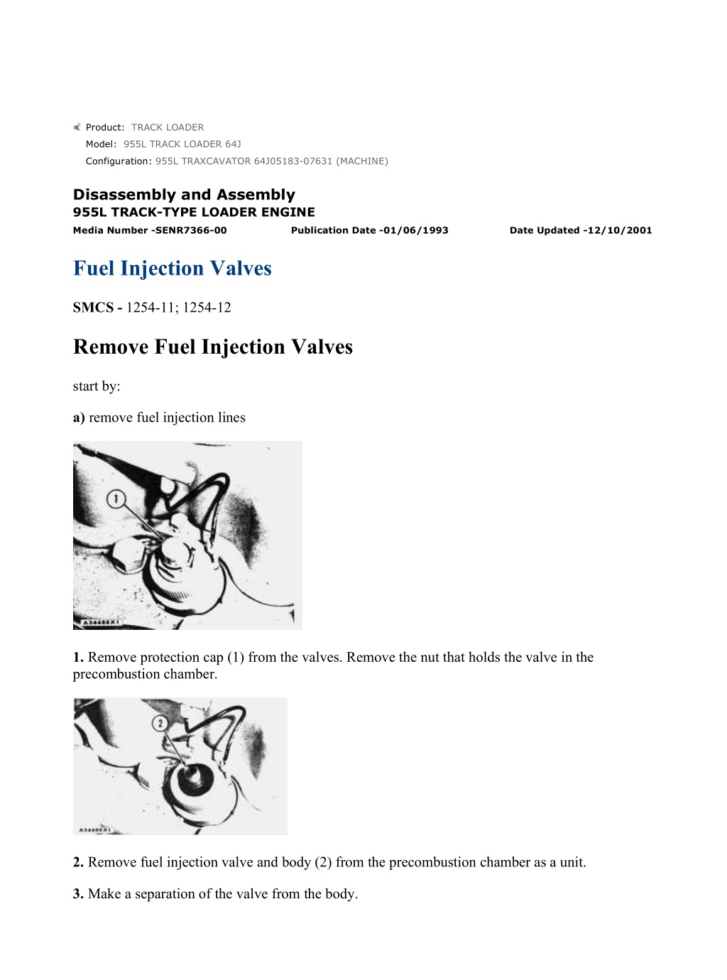
955L TRAXCAVATOR 64J05183-07631 (MACHINE)(UEH0781S - 00) - Document... 1/2 Product: TRACK LOADER Model: 955L TRACK LOADER 64J Configuration: 955L TRAXCAVATOR 64J05183-07631 (MACHINE) Disassembly and Assembly 955L TRACK-TYPE LOADER ENGINE Media Number -SENR7366-00 Publication Date -01/06/1993 Date Updated -12/10/2001 Fuel Injection Valves SMCS - 1254-11; 1254-12 Remove Fuel Injection Valves start by: a) remove fuel injection lines 1. Remove protection cap (1) from the valves. Remove the nut that holds the valve in the precombustion chamber. 2. Remove fuel injection valve and body (2) from the precombustion chamber as a unit. 3. Make a separation of the valve from the body. https://127.0.0.1/sisweb/sisweb/techdoc/techdoc_print_page.jsp?returnurl=/sis... 2021/12/9
955L TRAXCAVATOR 64J05183-07631 (MACHINE)(UEH0781S - 00) - Document... 2/2 Install Fuel Injection Valves 1. Install fuel injection valve (1) hand tight on body (2). 2. Install the valve and the body in the precombustion chamber. 3. Inspect the seals on the nut that holds valve (1) in the precombustion chamber. Make a replacement of the seals if they are damaged. Install the nut in the precombustion chamber. Tighten the nut to a torque of 105 5 lb. ft. (142.4 6.8 N m). end by: a) install fuel injection lines https://127.0.0.1/sisweb/sisweb/techdoc/techdoc_print_page.jsp?returnurl=/sis... 2021/12/9
955L TRAXCAVATOR 64J05183-07631 (MACHINE)(UEH0781S - 00) - Document... 1/3 Product: TRACK LOADER Model: 955L TRACK LOADER 64J Configuration: 955L TRAXCAVATOR 64J05183-07631 (MACHINE) Disassembly and Assembly 955L TRACK-TYPE LOADER ENGINE Media Number -SENR7366-00 Publication Date -01/06/1993 Date Updated -12/10/2001 Precombustion Chambers SMCS - 1106-11; 1106-12 Remove Precombustion Chambers start by: a) remove fuel injection valves 1. Remove the coolant from the cooling system. 2. Disconnect the wire from the glow plug. Remove glow plug (1) from the precombustion chamber with tool (A). https://127.0.0.1/sisweb/sisweb/techdoc/techdoc_print_page.jsp?returnurl=/sis... 2021/12/9
https://www.ebooklibonline.com Hello dear friend! Thank you very much for reading. Enter the link into your browser. The full manual is available for immediate download. https://www.ebooklibonline.com
955L TRAXCAVATOR 64J05183-07631 (MACHINE)(UEH0781S - 00) - Document... 2/3 3. Install tool (B) in the precombustion chamber. 4. Loosen the precombustion chamber from the cylinder head. Remove precombustion chamber (2). Install Precombustion Chambers 1. Install a new O-ring seal (2) on the precombustion chamber. 2. Put 9M3710 Anti-Seize Compound on the precombustion chamber threads. Install the thinner gasket on the precombustion chamber. 3. Put liquid soap on the bore in the cylinder head and O-ring seal (2). Install precombustion chamber (1) in the cylinder head. Tighten the chamber to a torque of 150 10 lb. ft. (203.4 13.6 N m) with tool (A). 4. If the opening for the glow plug is not in the "GO" range position, remove the precombustion chamber and install a new gasket as shown in the illustration. 5. Put 9M3710 Anti-Seize Compound on the threads of the glow plug. Install glow plug (4) in the precombustion chamber with tool (B). Tighten the glow plug to a torque of 120 24 lb. in. (13.6 2.7 N m). https://127.0.0.1/sisweb/sisweb/techdoc/techdoc_print_page.jsp?returnurl=/sis... 2021/12/9
955L TRAXCAVATOR 64J05183-07631 (MACHINE)(UEH0781S - 00) - Document... 3/3 6. Connect wire (3) to the glow plug. 7. Fill cooling system to the correct level. end by: a) install fuel injection valves https://127.0.0.1/sisweb/sisweb/techdoc/techdoc_print_page.jsp?returnurl=/sis... 2021/12/9
955L TRAXCAVATOR 64J05183-07631 (MACHINE)(UEH0781S - 00) - Document... 1/8 Product: TRACK LOADER Model: 955L TRACK LOADER 64J Configuration: 955L TRAXCAVATOR 64J05183-07631 (MACHINE) Disassembly and Assembly 955L TRACK-TYPE LOADER ENGINE Media Number -SENR7366-00 Publication Date -01/06/1993 Date Updated -12/10/2001 Turbocharger SMCS - 1052-11; 1052-12; 1052-15; 1052-16 Remove Turbocharger 1. Loosen clamps (1). Slide the hose toward the turbocharger as far as possible. 2. Loosen the clamps for the hose on the other side of the turbocharger. Slide the hose on to the pipe. 3. Remove oil supply line (2) and disconnect oil return line (3) from the bottom of the turbocharger. 4. Remove bolts (5) from each side of the turbocharger. Remove turbocharger (4) from the exhaust manifold. Install Turbocharger 1. Put 9M3710 Anti-Seize Compound on the threads of the four bolts for the turbocharger. https://127.0.0.1/sisweb/sisweb/techdoc/techdoc_print_page.jsp?returnurl=/sis... 2021/12/9
955L TRAXCAVATOR 64J05183-07631 (MACHINE)(UEH0781S - 00) - Document... 2/8 2. Put turbocharger (1) in position on the exhaust manifold and install the bolts that hold the turbocharger in place. Tighten the bolts to a torque of 40 4 lb. ft. (54.2 5.4 N m). 3. Connect oil return line (3) to the bottom of the turbocharger. 4. Put clean engine oil in the opening in the turbocharger for the oil supply line and install oil supply line (2). 5. Move hose (4) into position and tighten the two clamps. Move the hose, which is on the other side of the turbocharger, into position and tighten the two clamps. Disassemble Turbocharger start by: a) remove turbocharger 1. Put the turbocharger in position tool (A). https://127.0.0.1/sisweb/sisweb/techdoc/techdoc_print_page.jsp?returnurl=/sis... 2021/12/9
955L TRAXCAVATOR 64J05183-07631 (MACHINE)(UEH0781S - 00) - Document... 3/8 2. Put a mark on compressor housing (1) and the backplate assembly for use at assembly. Remove the compressor housing from the backplate assembly. 3. Change the position of tool (A) so the compressor wheel is up as shown. 4. Put a mark on housing (2) and turbine housing (3) so that the housing can be put back in the same position in the turbine housing at assembly. 5. Remove the bolts, lockplates and clamps that hold the housing in the turbine housing and remove the housing. 6. Put the housing in position on tool (B). 7. Remove nut (5) from the shaft. NOTICE Do not put a side force on the shaft when the nut is removed. 8. Remove compressor wheel (4) from the shaft. 9. Remove the housing from the shaft. https://127.0.0.1/sisweb/sisweb/techdoc/techdoc_print_page.jsp?returnurl=/sis... 2021/12/9
955L TRAXCAVATOR 64J05183-07631 (MACHINE)(UEH0781S - 00) - Document... 4/8 10. Remove shroud (6) from the turbine wheel and shaft. 11. Remove seal ring (7) from the turbine wheel. 12. Put a mark on the housing and backplate assembly for use at assembly. Remove the bolts and plates that hold the housing to the backplate assembly. Remove the housing. 13. Remove bearing (8), collar (9) and the seal ring from backplate assembly (10). 14. Remove the seal ring and bearing from the collar. 15. Remove seal ring (11) from the housing. 16. Remove the snap ring, bearing (12) and the snap ring from each side of the housing. Assemble Turbocharger https://127.0.0.1/sisweb/sisweb/techdoc/techdoc_print_page.jsp?returnurl=/sis... 2021/12/9
955L TRAXCAVATOR 64J05183-07631 (MACHINE)(UEH0781S - 00) - Document... 5/8 1. Make sure all oil passages are clean and free of all dirt or foreign material. Put clean engine oil on all of the parts before assembly. 2. Install the inner snap ring, bearing (1) and snap ring (2) in each side of the housing. NOTE: The snap rings must be installed with the round side toward the bearing. 3. Install the seal ring on collar (4). 4. Put bearing (3) in position on the collar. NOTICE The oil grooves in the bearing must be clean and free of all dirt or foreign material. The bearing must be installed with the oil grooves toward the housing. 5. Put the bearing and collar in position on the housing so that the oil grooves in the bearing are toward the housing and the holes in the bearing are in alignment with the pins in the housing. NOTICE Be extra careful during installation of the bearing and collar not to cause damage to the seal ring on the collar. 6. Install the seal ring on the housing. https://127.0.0.1/sisweb/sisweb/techdoc/techdoc_print_page.jsp?returnurl=/sis... 2021/12/9
955L TRAXCAVATOR 64J05183-07631 (MACHINE)(UEH0781S - 00) - Document... 6/8 7. Put the backplate assembly in position on the housing respective to the marks put on the housing and backplate at disassembly. Install the plates and bolts. Tighten the bolts to a torque of 50 10 lb. in. (67.8 13.6 N m). 8. Install shroud (5) on the housing. 9. Install seal ring (7). Carefully install turbine wheel and shaft (6) in the housing. 10. Put the housing, turbine wheel and shaft, and the backplate assembly in position on tool (A). 11. Install compressor wheel (8) on the turbine shaft. https://127.0.0.1/sisweb/sisweb/techdoc/techdoc_print_page.jsp?returnurl=/sis... 2021/12/9
955L TRAXCAVATOR 64J05183-07631 (MACHINE)(UEH0781S - 00) - Document... 7/8 12. Put clean engine oil on the threads of the shaft. Install the nut that holds the compressor wheel in place. Tighten the nut to a torque of 20 lb. in. (2.24 N m). Put a mark on the nut and shaft. Tighten the nut 100 more. NOTICE When the nut is tightened, do not put a side force on the shaft. 13. If the turbine housing was removed from tool (B), put the turbine housing in position on tool (B). 14. Put the housing and wheels in position in the turbine housing respective to the marks put on the housings at disassembly. 15. Put 9M3710 Anti-Seize Compound on the threads of bolts (9). Install the clamps, lockplates, and the bolts (9). Install the clamps, lockplates, and the bolts. Tighten the bolts to a torque of 115 15 lb. in. (13 1.7 N m). Bend the lockplates against the bolt heads. 16. Put compressor housing (10) in position on the backplate assembly respective to the marks put on the housing and backplate assembly at disassembly. https://127.0.0.1/sisweb/sisweb/techdoc/techdoc_print_page.jsp?returnurl=/sis... 2021/12/9
955L TRAXCAVATOR 64J05183-07631 (MACHINE)(UEH0781S - 00) - Document... 8/8 17. Install the clamps, lockplates, and bolts that hold the compressor housing in place. Tighten the bolts to a torque of 115 15 lb. in. (13 1.7 N m). Bend the lockplates against the bolt heads. 18. Remove the turbocharger from tool (B). end by: a) install turbocharger https://127.0.0.1/sisweb/sisweb/techdoc/techdoc_print_page.jsp?returnurl=/sis... 2021/12/9
955L TRAXCAVATOR 64J05183-07631 (MACHINE)(UEH0781S - 00) - Document... 1/3 Product: TRACK LOADER Model: 955L TRACK LOADER 64J Configuration: 955L TRAXCAVATOR 64J05183-07631 (MACHINE) Disassembly and Assembly 955L TRACK-TYPE LOADER ENGINE Media Number -SENR7366-00 Publication Date -01/06/1993 Date Updated -12/10/2001 Exhaust Manifold SMCS - 1059-11; 1059-12 Remove Exhaust Manifold start by: a) remove fuel filter base b) remove turbocharger c) remove fuel injection lines 1. Remove bolts (2) and remove elbow (1) from the muffler. https://127.0.0.1/sisweb/sisweb/techdoc/techdoc_print_page.jsp?returnurl=/sis... 2021/12/9
955L TRAXCAVATOR 64J05183-07631 (MACHINE)(UEH0781S - 00) - Document... 2/3 2. Disconnect line (4) from the governor. Remove exhaust manifold guard (3). 3. Remove nuts (6) and the washer that hold the manifold to the cylinder head. Remove manifold (5) from the studs. Install Exhaust Manifold 1. Inspect the gaskets for the manifold and make a replacement if they are damaged. Put 9M3710 Anti-Seize Compound on the threads of the studs and nuts for the manifold. Put manifold (1) in position on the cylinder head and install the washers and nuts. https://127.0.0.1/sisweb/sisweb/techdoc/techdoc_print_page.jsp?returnurl=/sis... 2021/12/9
955L TRAXCAVATOR 64J05183-07631 (MACHINE)(UEH0781S - 00) - Document... 3/3 2. Install the two spacers, and install exhaust manifold guard (2) with two nuts. Connect line (3) to governor (4). 3. Put 9M3710 Anti-Seize Compound on the threads of the bolts for the elbow and install elbow (5) to the muffler. end by: a) install fuel injection lines b) install turbocharger c) install fuel filter base https://127.0.0.1/sisweb/sisweb/techdoc/techdoc_print_page.jsp?returnurl=/sis... 2021/12/9
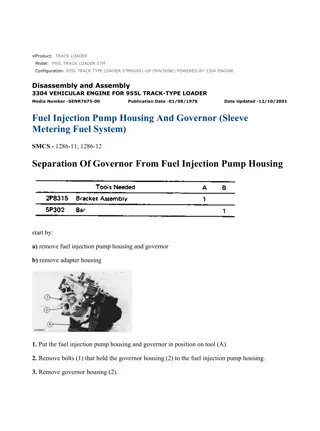
955L TRAXCAVATOR 64J05183-07631 (MACHINE)(UEH0781S - 00) - Document... 1/5 Product: TRACK LOADER Model: 955L TRACK LOADER 64J Configuration: 955L TRAXCAVATOR 64J05183-07631 (MACHINE) Disassembly and Assembly 955L TRACK-TYPE LOADER ENGINE Media Number -SENR7366-00 Publication Date -01/06/1993 Date Updated -12/10/2001 Fuel Injection Pump Housing And Governor SMCS - 1286-11; 1286-12 Remove Fuel Injection Pump Housing And Governor 1. Put the No. 1 piston on top center compression. 2. Put the No. 1 piston at top center compression as follows: a) Turn the crankshaft clockwise (as seen from the front of the engine until a 3/8"-16 NC bolt (1) 31/2" long can be installed through the timing hole in the flywheel housing and into the hole in the flywheel. NOTE: Never turn the crankshaft counterclockwise to install the bolt in the flywheel. b) Disconnect the breather from the valve cover. The rocker arms can be seen through the breather hole for No. 1 piston. c) Check to see if both rocker arms can be moved backward and forward by hand through the breather hole. NOTE: The No. 1 piston is at the top center compression position when the bolt is installed in the flywheel and the rocker arms for the No. 1 piston can be moved backward and forward. https://127.0.0.1/sisweb/sisweb/techdoc/techdoc_print_page.jsp?returnurl=/sis... 2021/12/9
955L TRAXCAVATOR 64J05183-07631 (MACHINE)(UEH0781S - 00) - Document... 2/5 d) If both rocker arms can not be moved, the No. 1 piston is not at the top center compression. Remove the bolt from the flywheel. Turn the engine clockwise as seen from the front of the engine one full turn 360 and install the bolt again. 3. Disconnect fuel injection lines (1) and (2) as a unit respectively. Put protection caps on all openings in the fuel lines to keep dirt or foreign material out of the fuel system. 4. Remove fuel filter (3) with tool (A). 5. Disconnect governor control linkage (4). 6. Remove fuel line (5) that connects the fuel filter base to the governor. Remove oil tube (7) from the bottom of the turbocharger and the fuel injection pump. 7. Disconnect air line (6) from the fuel ratio control. 8. Remove oil tube (10) that connects the engine block to the top of the turbocharger as a unit. Disconnect fuel pump overflow tube (9) and fuel pressure sensing line (8). https://127.0.0.1/sisweb/sisweb/techdoc/techdoc_print_page.jsp?returnurl=/sis... 2021/12/9
955L TRAXCAVATOR 64J05183-07631 (MACHINE)(UEH0781S - 00) - Document... 3/5 9. Remove the nuts that hold the timing gear plate and remove timing gear plate (11). 10. Loosen center line bolt (12), that holds the fuel injection pump drive gear to the fuel injection pump camshaft until the washer is approximately 1/8 in. (3.2 mm) away from the drive gear. Do not remove the bolt at this time. 11. Install tooling (B) on the drive gear. Tighten the center bolt in tooling (B) until the drive gear is loose. Remove tooling (B), bolt (12) and the washer. The drive gear will stay in the timing gear cover. 12. Remove the nuts that hold the fuel injection pump housing and governor to the timing gear cover and remove fuel injection pump housing and governor (13) as a unit. Install Fuel Injection Pump Housing And Governor 1. Put the No. 1 piston at the top center compression position before the fuel injection pump housing and governor is installed on the engine with the following procedure. https://127.0.0.1/sisweb/sisweb/techdoc/techdoc_print_page.jsp?returnurl=/sis... 2021/12/9
955L TRAXCAVATOR 64J05183-07631 (MACHINE)(UEH0781S - 00) - Document... 4/5 a) Put fuel injection pump housing and governor (1) in position on the machine and install washer and bolt finger tight. b) Install timing pin (2) in hole in the rear of torque spring cover. c) Turn the crankshaft in the direction of engine rotation and install the timing bolt in the flywheel. NOTE: Never turn the crankshaft backward to install the bolt in the flywheel. The No. 1 piston is at the top center compression position when the bolt is installed in the flywheel, and both rocker arms for the No. 1 piston can be moved backward and forward. 2. With the timing bolt and pin in position, put 50 lb. ft. (67.8 N m) torque on drive gear in the clockwise direction (as viewed from the front of the engine). With the 50 lb. ft. (67.8 N m) torque in application on the drive gear, tighten the drive bolt to a torque of 110 5 lb. ft. (149.2 6.8 N m). Remove the timing bolt and pin. 3. Install cover (3) for the timing gear. Tighten the nuts that hold the cover to a torque of 20 5 lb. ft. (27.1 6.8 N m). 4. Install bracket (4) and tube that makes a connection from the turbocharger to the engine. https://127.0.0.1/sisweb/sisweb/techdoc/techdoc_print_page.jsp?returnurl=/sis... 2021/12/9
Suggest: For more complete manuals. Please go to the home page. https://www.ebooklibonline.com If the above button click is invalid. Please download this document first, and then click the above link to download the complete manual. Thank you so much for reading
955L TRAXCAVATOR 64J05183-07631 (MACHINE)(UEH0781S - 00) - Document... 5/5 5. Install oil tube (6) that connects to the fuel injection pump and to the bottom of the turbocharger. Install the fuel line that connects the fuel filter base to the governor and air line (7) that connects to the fuel ratio control. 6. Connect fuel pressure sensing line (9) and fuel pump overflow tube (11). 7. Remove the protection caps and the plugs. Connect fuel lines (8) and (10) as a unit respectively. Tighten the nuts for the fuel lines to a torque of 30 5 lb. ft. (40.7 6.8 N m) with tool (B). 8. Connect governor control linkage (12) with a pin and a cotter pin. 9. Install the fuel filter with tool (A). https://127.0.0.1/sisweb/sisweb/techdoc/techdoc_print_page.jsp?returnurl=/sis... 2021/12/9
955L TRAXCAVATOR 64J05183-07631 (MACHINE)(UEH0781S - 00) - Document... 1/3 Product: TRACK LOADER Model: 955L TRACK LOADER 64J Configuration: 955L TRAXCAVATOR 64J05183-07631 (MACHINE) Disassembly and Assembly 955L TRACK-TYPE LOADER ENGINE Media Number -SENR7366-00 Publication Date -01/06/1993 Date Updated -12/10/2001 Fuel Ratio Control SMCS - 1278-11; 1278-12; 1278-15; 1278-16 Remove Fuel Ratio Control start by: a) remove fuel injection pump housing and governor NOTE: The fuel injection pump housing and governor does not have to be removed from the machine for the removal of the fuel ratio control. 1. Remove two bolts (2) from the fuel ratio control. 2. Remove fuel ratio control (1) from the adapter housing. Install Fuel Ratio Control https://127.0.0.1/sisweb/sisweb/techdoc/techdoc_print_page.jsp?returnurl=/sis... 2021/12/9
https://www.ebooklibonline.com Hello dear friend! Thank you very much for reading. Enter the link into your browser. The full manual is available for immediate download. https://www.ebooklibonline.com


