Caterpillar Cat 955K 955L TRACK LOADER (Prefix 85J) Service Repair Manual Instant Download (85J06247-09509)
Please open the website below to get the complete manualnn//
Download Presentation

Please find below an Image/Link to download the presentation.
The content on the website is provided AS IS for your information and personal use only. It may not be sold, licensed, or shared on other websites without obtaining consent from the author. Download presentation by click this link. If you encounter any issues during the download, it is possible that the publisher has removed the file from their server.
E N D
Presentation Transcript
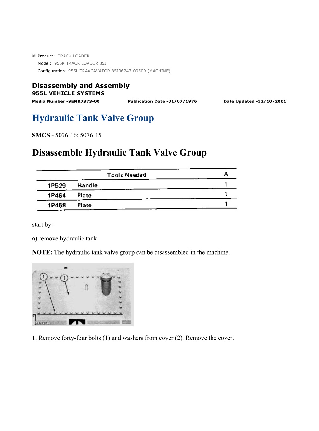
955L TRAXCAVATOR 85J06247-09509 (MACHINE)(UEG0700S - 00) - Document... 1/33 Product: TRACK LOADER Model: 955K TRACK LOADER 85J Configuration: 955L TRAXCAVATOR 85J06247-09509 (MACHINE) Disassembly and Assembly 955L VEHICLE SYSTEMS Media Number -SENR7373-00 Publication Date -01/07/1976 Date Updated -12/10/2001 Hydraulic Tank Valve Group SMCS - 5076-16; 5076-15 Disassemble Hydraulic Tank Valve Group start by: a) remove hydraulic tank NOTE: The hydraulic tank valve group can be disassembled in the machine. 1. Remove forty-four bolts (1) and washers from cover (2). Remove the cover. https://127.0.0.1/sisweb/sisweb/techdoc/techdoc_print_page.jsp?returnurl=/sis... 2021/12/17
955L TRAXCAVATOR 85J06247-09509 (MACHINE)(UEG0700S - 00) - Document... 2/33 2. Remove the retaining bolts that hold filter outlet tube assembly (4) and filter inlet tube assembly (3). Remove tube assemblies (3) and (4). 3. Disconnect rod assemblies (5) that are connected to the tilt and lift controls. 4. Remove bolts (6) and washers that hold the bottom cover. 5. Install two 1/2"-13 NC forged eyebolts in tank assembly (7). Fasten a hoist to the tank assembly and remove it. Weight of the tank assembly is 225 lb. (102 kg). https://127.0.0.1/sisweb/sisweb/techdoc/techdoc_print_page.jsp?returnurl=/sis... 2021/12/17
955L TRAXCAVATOR 85J06247-09509 (MACHINE)(UEG0700S - 00) - Document... 3/33 6. Remove two bolts (8) and washers that hold lift control lockout roller and lever (9) to the bottom cover. 7. Remove lift control lockout roller and lever (9). Make sure lift control lever spring (10) is not connected. 8. Remove lift control lever spring (10). 9. Remove nut (11) and washer and remove the bolt. Remove lever (12). https://127.0.0.1/sisweb/sisweb/techdoc/techdoc_print_page.jsp?returnurl=/sis... 2021/12/17
https://www.ebooklibonline.com Hello dear friend! Thank you very much for reading. Enter the link into your browser. The full manual is available for immediate download. https://www.ebooklibonline.com
955L TRAXCAVATOR 85J06247-09509 (MACHINE)(UEG0700S - 00) - Document... 4/33 10. Inspect O-ring seals (13) and make replacements if they have damage. 11. Make a separation of lift cylinder spool linkage (14) and lift cylinder spool (15) by the removal of retainer (16) and pin (17). 12. Remove retaining bolts (19) and disconnect tilt control lever spring (20). 13. Remove pin (21) and remove tilt control lockout roller and lever (18). 14. Remove tilt control lever spring (20). https://127.0.0.1/sisweb/sisweb/techdoc/techdoc_print_page.jsp?returnurl=/sis... 2021/12/17
955L TRAXCAVATOR 85J06247-09509 (MACHINE)(UEG0700S - 00) - Document... 5/33 15. Remove links (24). Remove nut and washer (22) and remove roller (23). 16. Remove nut and washer (25) and remove bolts (26). Remove the lever. 17. Remove O-ring seal (27). Inspect the seal and make a replacement if it has damage. 18. Remove three retaining bolts (28) that hold bucket positioner slave cylinder (30) to the bottom cover. https://127.0.0.1/sisweb/sisweb/techdoc/techdoc_print_page.jsp?returnurl=/sis... 2021/12/17
955L TRAXCAVATOR 85J06247-09509 (MACHINE)(UEG0700S - 00) - Document... 6/33 19. Remove bucket positioner slave cylinder (29). 20. Remove slave cylinder spool (31) from slave cylinder body (30). NOTE: The bucket positioner slave cylinder also has a drain plug. 21. Remove O-ring seals (32). Inspect the seals and make replacements if damaged. 22. Remove the retainer and pin and disconnect tilt valve spool control rod (34) from tilt valve spool (33). https://127.0.0.1/sisweb/sisweb/techdoc/techdoc_print_page.jsp?returnurl=/sis... 2021/12/17
955L TRAXCAVATOR 85J06247-09509 (MACHINE)(UEG0700S - 00) - Document... 7/33 23. Remove retaining bolts (35) that hold bracket assembly (36) and the lift and tilt control cam levers. 24. Remove bracket assembly (36). 25. Remove tilt valve spool and lift valve spool control rods (37). 26. Remove two retaining bolts (38). Remove screen assembly (39). https://127.0.0.1/sisweb/sisweb/techdoc/techdoc_print_page.jsp?returnurl=/sis... 2021/12/17
955L TRAXCAVATOR 85J06247-09509 (MACHINE)(UEG0700S - 00) - Document... 8/33 27. Remove bolt (40) and remove lift control cam lever (41) from shaft (42). 28. Remove key (43) from shaft (42). 29. Remove bolt (45) and remove lift cylinder control lever (44) from shaft (42). 30. Remove shaft (42) and key (47) from the bracket assembly. Remove tilt control cam lever (46). https://127.0.0.1/sisweb/sisweb/techdoc/techdoc_print_page.jsp?returnurl=/sis... 2021/12/17
955L TRAXCAVATOR 85J06247-09509 (MACHINE)(UEG0700S - 00) - Document... 9/33 31. Remove bearings (48) from tilt control cam lever (46) and lift control cam lever (41) with tooling (A). 32. Remove bearings (49) from bracket assembly (36) with tooling (A). https://127.0.0.1/sisweb/sisweb/techdoc/techdoc_print_page.jsp?returnurl=/sis... 2021/12/17
955L TRAXCAVATOR 85J06247-09509 (MACHINE)(UEG0700S - 00) - Docume... 10/33 33. Remove the retaining bolts that hold lift and tilt control valve group (50). Remove control valve group (50). 34. Remove bolts (51) and lockwashers. Remove stop (53) and main pressure relief valve tube assembly (52). 35. Remove four bolts (54) and lockwashers and remove housing (55). Housing (55) holds the tilt circuit relief valve for the rod end of the tilt cylinders and the tilt circuit make-up valve. 36. Remove plug (56) and the seal from the tilt circuit make-up valve. 37. Remove spring (57) and valve (58). https://127.0.0.1/sisweb/sisweb/techdoc/techdoc_print_page.jsp?returnurl=/sis... 2021/12/17
955L TRAXCAVATOR 85J06247-09509 (MACHINE)(UEG0700S - 00) - Docume... 11/33 38. Remove plug (59) and the seal. Inspect the seal and make a replacement if damaged. 39. Remove plug (60) with shims from valve (61). 40. Remove inner spring (65) and outer spring (64) from the rod end circuit of the relief valve for tilt cylinders. 41. Remove washer (63) and valve (62). 42. Remove valve body (61) and spacer (66). https://127.0.0.1/sisweb/sisweb/techdoc/techdoc_print_page.jsp?returnurl=/sis... 2021/12/17
955L TRAXCAVATOR 85J06247-09509 (MACHINE)(UEG0700S - 00) - Docume... 12/33 43. Remove four bolts (67) and lockwashers. Remove housing (68) that holds the lift circuit make- up valve. 44. Remove plug (69) and the seal. Inspect the seal and make a replacement if the seal is broken or damaged. 45. Remove spring (70) and lift circuit make-up valve (71) from the housing. 46. Remove manifold (72) and the head end of the single sensing relief valve for the tilt cylinders. https://127.0.0.1/sisweb/sisweb/techdoc/techdoc_print_page.jsp?returnurl=/sis... 2021/12/17
955L TRAXCAVATOR 85J06247-09509 (MACHINE)(UEG0700S - 00) - Docume... 13/33 47. Remove plug (73) with shims from the relief valve body (74). Disassemble the remainder of the relief valve as in Steps 40 through 42. 48. Remove two bolts (75) and lockwashers. Remove retainer (76). 49. Remove two bolts (77) and lockwashers. Remove retainer (78). 50. Remove two bolts (80) and lockwashers. Remove main pressure relief valve (79). https://127.0.0.1/sisweb/sisweb/techdoc/techdoc_print_page.jsp?returnurl=/sis... 2021/12/17
955L TRAXCAVATOR 85J06247-09509 (MACHINE)(UEG0700S - 00) - Docume... 14/33 51. Remove O-ring seal (81). Inspect and make a replacement if damaged or broken. 52. Lockwire (82) can be removed if adjustment is needed. NOTE: There are no replacement parts in this valve. 53. Turn nut (84) and setscrew (83) to change the relief valve pressure. 54. Remove four bolts (85) and lockwashers. Remove two covers (86) from the lift circuit check valve and the tilt circuit check valve. 55. Remove screw (88) and washer (87) from the tilt cylinder spool. 56. Remove retainer (89) and spring (90). https://127.0.0.1/sisweb/sisweb/techdoc/techdoc_print_page.jsp?returnurl=/sis... 2021/12/17
955L TRAXCAVATOR 85J06247-09509 (MACHINE)(UEG0700S - 00) - Docume... 15/33 57. Remove spacer (91) from tilt cylinder spool (92). 58. Remove the cylinder spool (93) from the valve group body. 59. Remove screw (96), spacer (94) and spacer (95) from the lift cylinder spool. 60. Remove inner spring (97) and outer spring (98). https://127.0.0.1/sisweb/sisweb/techdoc/techdoc_print_page.jsp?returnurl=/sis... 2021/12/17
955L TRAXCAVATOR 85J06247-09509 (MACHINE)(UEG0700S - 00) - Docume... 16/33 61. Remove spacer (99) from the lift cylinder spool. 62. Remove lift cylinder spool (100) from the valve group body. 63. Remove plugs (101) and seals. Inspect seals and make replacements if broken or damaged. NOTE: The plugs can be removed as shown. https://127.0.0.1/sisweb/sisweb/techdoc/techdoc_print_page.jsp?returnurl=/sis... 2021/12/17
955L TRAXCAVATOR 85J06247-09509 (MACHINE)(UEG0700S - 00) - Docume... 17/33 64. Remove springs (103) and remove lift and tilt circuit check valves (102). 65. Remove three plugs (104) and seals from the valve group body. Inspect the seals and make replacements if broken or damaged. Assemble Hydraulic Tank Valve Group NOTE: Put SAE 10 oil on all of the parts of the hydraulic tank valve group. Make sure all the parts are clean and free of dirt and foreign material before the valve group is assembled. 1. Install three plugs (1) and seals in the valve body. Tighten plugs (1) to a torque of 80 2 lb. ft. (108.5 2.7 N m). https://127.0.0.1/sisweb/sisweb/techdoc/techdoc_print_page.jsp?returnurl=/sis... 2021/12/17
955L TRAXCAVATOR 85J06247-09509 (MACHINE)(UEG0700S - 00) - Docume... 18/33 2. Install lift circuit check valve (3) and spring (2) in the body. Install tilt circuit check valve (5) and spring (4) in the control valve group body. 3. Install plugs (6) and seals in the valve body. 4. Install lift cylinder spool (7) in the valve body as shown. 5. Install spacer (8) on the lift cylinder spool as shown. https://127.0.0.1/sisweb/sisweb/techdoc/techdoc_print_page.jsp?returnurl=/sis... 2021/12/17
955L TRAXCAVATOR 85J06247-09509 (MACHINE)(UEG0700S - 00) - Docume... 19/33 6. Put inner spring (9) and outer spring (10) in position on spool (7). 7. Install spacers (11) and (12). Install screw (13). Install retainer (15) and two bolts (14) that hold the valve in position in the valve body. 8. Install tilt cylinder spool (16) in the bore of the valve body as shown. Make sure the spool has no wear or damage. The spool must be free to move in the bore. https://127.0.0.1/sisweb/sisweb/techdoc/techdoc_print_page.jsp?returnurl=/sis... 2021/12/17
955L TRAXCAVATOR 85J06247-09509 (MACHINE)(UEG0700S - 00) - Docume... 20/33 9. Put spacer (17) on the tilt cylinder spool with flat surface toward the valve body as shown. 10. Put spring (18) in position on the tilt cylinder spool. Install retainer (21). washer (20) and screw (19). 11. Install retainer (22), two bolts (23) and washers. https://127.0.0.1/sisweb/sisweb/techdoc/techdoc_print_page.jsp?returnurl=/sis... 2021/12/17
Suggest: For more complete manuals. Please go to the home page. https://www.ebooklibonline.com If the above button click is invalid. Please download this document first, and then click the above link to download the complete manual. Thank you so much for reading
955L TRAXCAVATOR 85J06247-09509 (MACHINE)(UEG0700S - 00) - Docume... 21/33 12. Install covers (24), four bolts (25) and lockwashers to hold the plugs and the check valves in the valve body. 13. Put valve group body (26) on the bottom plate of the hydraulic tank. Install two bolts (27) and lockwashers. Tighten bolts to a torque of 24 2 lb. ft. (32.5 2.7 N m). https://127.0.0.1/sisweb/sisweb/techdoc/techdoc_print_page.jsp?returnurl=/sis... 2021/12/17
955L TRAXCAVATOR 85J06247-09509 (MACHINE)(UEG0700S - 00) - Docume... 22/33 14. Assemble the single sensing relief valve for the head end circuit of the tilt cylinders. Install valve (33), washer (35), inner spring (30), and outer spring (32) in body (34). Install body (34) in manifold housing (36) and tighten to a torque of 50 3 lb. ft. (67.8 4.1 N m). 15. Install shims (29) and plug (28) in the body of the single sensing relief valve. Tighten the plug to a torque of 100 5 lb. ft. (135.6 6.8 N m). The shims have a thickness of .005 in. (0.13 mm). https://127.0.0.1/sisweb/sisweb/techdoc/techdoc_print_page.jsp?returnurl=/sis... 2021/12/17
https://www.ebooklibonline.com Hello dear friend! Thank you very much for reading. Enter the link into your browser. The full manual is available for immediate download. https://www.ebooklibonline.com


