Caterpillar Cat 666 666B WHEEL SCRAPER (Prefix 20G) Service Repair Manual Instant Download (20G00242 and up)
Please open the website below to get the complete manualnn//
Download Presentation

Please find below an Image/Link to download the presentation.
The content on the website is provided AS IS for your information and personal use only. It may not be sold, licensed, or shared on other websites without obtaining consent from the author. Download presentation by click this link. If you encounter any issues during the download, it is possible that the publisher has removed the file from their server.
E N D
Presentation Transcript
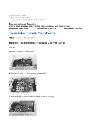
w 1/14(W) Product: WHEEL SCRAPER Model: 666 WHEEL SCRAPER 20G Configuration: 666B SCRAPER 20G00242-UP (MACHINE) POWERED BY D343 ENGINE Disassembly and Assembly 657B & 666B SCRAPER EIGHT SPEED TRANSMISSION AND TRANSFER GE Media Number -SENR7742-00 Publication Date -01/01/1978 Date Updated -12/10/2001 Transmission Hydraulic Control Valves SMCS - 3167-17; 3167-11; 3167-12 Remove Transmission Hydraulic Control Valves start by: a) remove hydraulic control cover 1. Remove six bolts (1). Remove priority valve (2). 2. Remove thirty-five bolts and washers (3). Remove cover (4). https://127.0.0.1/sisweb/sisweb/techdoc/techdoc_print_page.jsp?returnurl=/sisweb/siswe... 2021/3/2
w 2/14(W) 3. Remove the pressure control valve (5). Remove five bolts (7). Remove cover (6). 4. Remove selector valve (8). 5. Remove cotter pin (9). Slide tube (10) back. NOTICE There is an O-ring seal on the end of tube (10). 6. Remove plate (11). https://127.0.0.1/sisweb/sisweb/techdoc/techdoc_print_page.jsp?returnurl=/sisweb/siswe... 2021/3/2
w 3/14(W) 7. Remove the four nuts (12) that hold filter (13) to the transmission case. Remove filter (13). 8. Remove two sleeves (15) that connect oil manifold (14) to the filter group. 9. Install 1/4"-20 NC forged eyebolts. Remove two dowel pins (16). 10. Remove bolts (17). 11. Remove adapter (18). 12. Remove two sleeves (19). 13. Remove oil manifold (14) as a unit. Install Hydraulic Control Valves https://127.0.0.1/sisweb/sisweb/techdoc/techdoc_print_page.jsp?returnurl=/sisweb/siswe... 2021/3/2
https://www.ebooklibonline.com Hello dear friend! Thank you very much for reading. Enter the link into your browser. The full manual is available for immediate download. https://www.ebooklibonline.com
w 4/14(W) 1. Install oil manifold (1). Install two dowel pins (4). Install bolts (5) and tighten to a torque of 35 3 lb.ft. (45 4 N m). 2. Install the two sleeves (2) that connect the filter group to oil manifold. Check O-ring seals on sleeves. Make replacements if necessary. 3. Install the two sleeves (3) that connect the adapter to the oil manifold. Check O-ring seals on sleeves. Make replacements if necessary. 4. Install filter group (7) and adapter (6). 5. Install plate (10). Install tube (8) in manifold. Check O-ring seal (9). Make a replacement if necessary. 6. Install pin (11). https://127.0.0.1/sisweb/sisweb/techdoc/techdoc_print_page.jsp?returnurl=/sisweb/siswe... 2021/3/2
w 5/14(W) 7. Install selector valve (12). 8. Install cover (13). Install five bolts (14). 9. Install pressure control valve (15). 10. Install cover (16). Install bolts (17). Tighten the bolts to a torque of 22 3 lb.ft. (28 4 N m). https://127.0.0.1/sisweb/sisweb/techdoc/techdoc_print_page.jsp?returnurl=/sisweb/siswe... 2021/3/2
w 6/14(W) 11. Install priority valve (18). Install six bolts (19). Tighten the bolts to a torque of 22 3 lb.ft. (28 4 N m). Disassemble And Assemble Transmission Hydraulic Control Valves start by: a) remove hydraulic control valves 1. Disassemble shift cylinder priority valve as follows: a) Remove bolts and washers (1). b) Remove valve spool (2) from valve body. c) Remove two bolts and washers (3). Remove plate (4). There is a spring behind plate (4). https://127.0.0.1/sisweb/sisweb/techdoc/techdoc_print_page.jsp?returnurl=/sisweb/siswe... 2021/3/2
w 7/14(W) d) Remove valve spool (5) and spring (6) from valve body. e) Remove shims (7) from valve spool (5). f) Remove retaining ring (8) from valve spool. g) Remove ring (11), spring (10) and check valve (9). NOTE: Retaining ring (8) was removed in Step f. h) Remove bolts and washers (12). https://127.0.0.1/sisweb/sisweb/techdoc/techdoc_print_page.jsp?returnurl=/sisweb/siswe... 2021/3/2
w 8/14(W) i) Remove retainer (13) from valve body. j) Remove spacer (14). 2. Assemble shift cylinder and priority valve as follows: Install spacer (14) in valve body. Install retainer (13) in valve body. Install bolts and washers (12). Tighten to a torque of 22 3 lb.ft. (28 4 N m). Install check (9), spring (10) and ring (11) in spool (5). Install retaining ring (8) in valve spool (5). Install original amount of shims (7) in spool (5). Install valve spool (5) in valve body. Install spring (6). Install plate (4) and two bolts and washers (3). Tighten to a torque of 22 3 lb.ft. (28 4 N m). Install valve spool (2) in valve body. Install bolts and washers (1). Tighten to a torque of 22 3 lb.ft. (28 4 N m). 3. Disassemble the pressure control valve as follows: https://127.0.0.1/sisweb/sisweb/techdoc/techdoc_print_page.jsp?returnurl=/sisweb/siswe... 2021/3/2
w 9/14(W) a) Remove bolts (16) and cover (17) from pressure control valve body (15). b) Remove spring (24), load piston reset valve spool (23) and plug (22) from body (18). Remove load piston (26) and spacers. Remove stop (27), plunger (28) and spring (32). Remove load piston (33) and spacers. c) Remove stop (21), check valve (20) and spring (19) from valve body (15). Remove retainers (25), springs (30), retainers (29) and springs (31). d) Remove cover (34) from pressure control valve (15). e) Remove slug (35) and valve spool (36) (for the converter inlet relief) from valve body (15). Remove snap ring, retainer and plunger from valve spool (36). Remove spring (37) and flow control valve plunger (38). Remove valve spool (39) (for modulating relief pressure P2) and sleeve (40). Remove safety valve spool (41) and spring (44). Remove the spiral snap ring retainer, spring and poppet from valve spool (41). Remove valve spool (42) (for modulating relief pressure P1) and sleeve (43). Remove the spiral snap ring, retainer, spring and poppet from valve spool (42). https://127.0.0.1/sisweb/sisweb/techdoc/techdoc_print_page.jsp?returnurl=/sisweb/siswe... 2021/3/2
w 10/14(W) 4. Assemble the pressure control valve as follows: a) Install poppet (48), spring (46), retainer (47) and spiral snap ring (45) in valve spool (42) (for modulating relief pressure P1). b) Install plunger (52), spring (50), retainer (51) and snap ring (49) in valve spool (36) for the converter inlet relief. c) Install sleeve (43) and valve spool (42) (for modulating relief pressure P1) as shown in pressure control valve body (15). Install the poppet, spring, retainer and spiral snap ring in safety valve spool (41). Install spring (44) and valve spool (41) as shown. Install sleeve (40) and valve spool (39) (for modulating relief pressure P2) as shown. Install flow control valve plunger (38) and spring (37) as shown. Install valve spool (36) and slug (35) (for the converter inlet relief) as shown. Put cover (34) in position on valve body (15) and install the bolts that hold it in place. Tighten the bolts to a torque of 22 3 lb.ft. (28 4 N m). https://127.0.0.1/sisweb/sisweb/techdoc/techdoc_print_page.jsp?returnurl=/sisweb/siswe... 2021/3/2
w 11/14(W) d) Install spring (19), check valve (20) and stop (21) in valve body (15) as shown. Install slug (22) in load piston reset valve spool (23). Install spool (23) and spring (24) in body (18). Install load piston (26) and spacers in body (18) as shown. Install spring (32) in plunger (28). Install plunger (28) and stop (27) in body (18) as shown. Install load piston (33) and spacers in body (18) as shown. Install retainer (25), springs (30), retainer (29) and spring (31) in valve body (15) as shown. Install the other retainers (25) and (29) on the end of load pistons (26) and (33). Install cover (17) on body (18) and install body (18) on valve body (15) as shown. Tighten the bolts that hold the cover and valve bodies together to a torque of 22 3 lb.ft. (28 4 N m). https://127.0.0.1/sisweb/sisweb/techdoc/techdoc_print_page.jsp?returnurl=/sisweb/siswe... 2021/3/2
w 12/14(W) 5. Disassemble and assemble the selector valve as follows: a) Remove link assemblies (53) from the selector valve spools. b) Remove selector valve spools (54) from the selector valve body (55). https://127.0.0.1/sisweb/sisweb/techdoc/techdoc_print_page.jsp?returnurl=/sisweb/siswe... 2021/3/2
w 13/14(W) c) Install selector valve spools (54) in selector valve body (55) as shown. Install link assemblies (53) on the selector valve spools. The links will have to be adjusted when the selector valve is installed in the transmission. end by: a) install transmission hydraulic control valves Separation And Connection Of Transfer Gear And Transmission 1. Install one 5/8"-11 NC forged eyebolt in the transfer gear case. Fasten a hoist. 2. Remove cover (1). Remove the plug assembly that is behind the cover. https://127.0.0.1/sisweb/sisweb/techdoc/techdoc_print_page.jsp?returnurl=/sisweb/siswe... 2021/3/2
w 14/14(W) TYPICAL EXAMPLE 3. Remove the bolts that fasten the transfer gear case to the transmission. Make a separation of the transfer gears from the transmission. 4. Install one 5/8"-11 NC forged eyebolt in the transfer gear case. Fasten a hoist. 5. Install transfer gears on transmission. Install the bolts that hold the transmission to the transfer gear case. 6. Install plug assembly. Install cover (1). https://127.0.0.1/sisweb/sisweb/techdoc/techdoc_print_page.jsp?returnurl=/sisweb/siswe... 2021/3/2
w 1/22(W) Product: WHEEL SCRAPER Model: 666 WHEEL SCRAPER 20G Configuration: 666B SCRAPER 20G00242-UP (MACHINE) POWERED BY D343 ENGINE Disassembly and Assembly 657B & 666B SCRAPER EIGHT SPEED TRANSMISSION AND TRANSFER GE Media Number -SENR7742-00 Publication Date -01/01/1978 Date Updated -12/10/2001 Transfer Gear SMCS - 3159-16; 3159-15 Disassemble Transfer Gear start by: a) remove transmission and transfer gear as a unit b) separation of the transfer gear from the transmission https://127.0.0.1/sisweb/sisweb/techdoc/techdoc_print_page.jsp?returnurl=/sisweb/siswe... 2021/3/2
w 2/22(W) 1. Remove the bolts (1) that fasten the scavenge pump (2) to the transfer gear case. 2. Remove scavenge pump (2). Remove three O-ring seals (3) from pump. 3. Remove the two bolts (4) that hold the pump cover to pump. 4. Remove cover (5). Remove O-ring seal (6). 5. Remove two gears (7). https://127.0.0.1/sisweb/sisweb/techdoc/techdoc_print_page.jsp?returnurl=/sisweb/siswe... 2021/3/2
w 3/22(W) 6. Remove inner cover assembly (8). Remove two dowel pins (9). 7. Remove O-ring seal (10) from bottom cover. 8. Remove two bearings (11) from bottom cover with tooling (A). 9. Remove two bearings (12) from top cover with tooling (B). 10. Remove four bolts (13) from screen and cover assembly. https://127.0.0.1/sisweb/sisweb/techdoc/techdoc_print_page.jsp?returnurl=/sisweb/siswe... 2021/3/2
w 4/22(W) 11. Remove screen and cover assembly (14) from manifold. 12. Disassemble screen and cover assembly. 13. Remove bolts (15) and cover (16). 14. Remove magnetic filter assembly (17). https://127.0.0.1/sisweb/sisweb/techdoc/techdoc_print_page.jsp?returnurl=/sisweb/siswe... 2021/3/2
w 5/22(W) 15. Remove coupling (19). 16. Remove bolts (18) that hold the manifold assembly to the transfer gear case. 17. Install two 3/8"-16 NC forcing screws and make a separation of the manifold assembly from dowels. 18. Remove the manifold assembly (20) and gasket (21). 19. Remove the bolts (22) that hold the transmission pump to manifold cover. 20. Remove the transmission pump. Remove two O-ring seals (23). https://127.0.0.1/sisweb/sisweb/techdoc/techdoc_print_page.jsp?returnurl=/sisweb/siswe... 2021/3/2
w 6/22(W) 21. Remove bolts (24) that hold the pump cover to the pump. 22. Make a separation of inner cover assembly (25) and outer cover assembly (28) from body assembly (27). Remove two gears (26). 23. Remove O-ring seal (29). Remove two bearings (30) from inner cover assembly with tooling (A). 24. Remove O-ring seal (31). Remove outer cover assembly bearings (32) with tooling (A). https://127.0.0.1/sisweb/sisweb/techdoc/techdoc_print_page.jsp?returnurl=/sisweb/siswe... 2021/3/2
w 7/22(W) 25. Remove input gear bearing cage bolts (33). 26. Install two 3/8"-16 NC forcing screws (34). Loosen bearing cage from housing. 27. Remove bearing cage assembly (35) and shims (36) from housing. 28. Remove O-ring seal (37) from cage. Use a hammer and a punch to remove bearing cup (38). https://127.0.0.1/sisweb/sisweb/techdoc/techdoc_print_page.jsp?returnurl=/sisweb/siswe... 2021/3/2
w 8/22(W) 29. Loosen transmission pump drive gear bearing cage bolts (39). 30. Turn case over as shown. Remove output gear bearing cage bolts (40). 31. Install two 3/8"-16 NC forcing screws (41). Make a separation of cage from the housing. 32. Remove cage assembly (42) and shims (43) from the housing. https://127.0.0.1/sisweb/sisweb/techdoc/techdoc_print_page.jsp?returnurl=/sisweb/siswe... 2021/3/2
w 9/22(W) 33. Use a hammer and a punch to remove the bearing race (44) from the cage. 34. Remove output gear assembly (45). 35. Use tooling (C) to remove bearings from output gear assembly. 36. Remove input gear assembly (46). https://127.0.0.1/sisweb/sisweb/techdoc/techdoc_print_page.jsp?returnurl=/sisweb/siswe... 2021/3/2
Suggest: For more complete manuals. Please go to the home page. https://www.ebooklibonline.com If the above button click is invalid. Please download this document first, and then click the above link to download the complete manual. Thank you so much for reading
w 10/22(W) 37. Use tooling (D) to remove bearings from input gear assembly. 38. Remove bolts loosened in Step 29. Remove pump drive gear and cage assembly (47) from housing. Remove retaining ring (48) from cage assembly. 39. Make a separation of bearing assembly from cage assembly with a hammer and a punch as shown. NOTE: Punch goes through hole (49) as shown. 40. Remove bearing (50) from cage (51). https://127.0.0.1/sisweb/sisweb/techdoc/techdoc_print_page.jsp?returnurl=/sisweb/siswe... 2021/3/2
w 11/22(W) 41. Install tooling (E) and remove output gear bearing race (52) from housing. 42. Turn case over. Install tooling (F) and remove input gear bearing race (53). https://127.0.0.1/sisweb/sisweb/techdoc/techdoc_print_page.jsp?returnurl=/sisweb/siswe... 2021/3/2
https://www.ebooklibonline.com Hello dear friend! Thank you very much for reading. Enter the link into your browser. The full manual is available for immediate download. https://www.ebooklibonline.com

