Caterpillar Cat 3512B Industrial Engine (Prefix BR2) Service Repair Manual Instant Download (BR200001 and up)
Please open the website below to get the complete manualnn//
Download Presentation

Please find below an Image/Link to download the presentation.
The content on the website is provided AS IS for your information and personal use only. It may not be sold, licensed, or shared on other websites without obtaining consent from the author. Download presentation by click this link. If you encounter any issues during the download, it is possible that the publisher has removed the file from their server.
E N D
Presentation Transcript
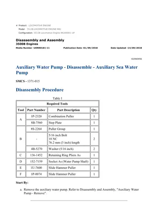
w 1/14(W) Product: INDUSTRIAL ENGINE Model: 3512B INDUSTRIAL ENGINE BR2 Configuration: 3512B Industrial Engine BR200001-UP Disassembly and Assembly 3500B Engines Media Number -UENR0181-11 Publication Date -01/09/2018 Date Updated -14/09/2018 i03351722 Auxiliary Water Pump - Disassemble - Auxiliary Pump (Type 1) SMCS - 1371-015 Disassembly Procedure Table 1 Required Tools Tool Part Number Part Description Qty A 1P-2320 Combination Puller (Two Jaw or Three Jaw) 1 B 193-8094 Spline Socket 1 C 193-8100 Socket (Impeller Nut) 1 D 1P-0510 Driver Gp 1 E 136-1452 Retaining Ring Pliers As 1 F 152-7159 Socket As (Water Pump Shaft) 1 G 1U-7600 Slide Hammer Puller Gp 1 H 1P-0074 Slide Hammer Puller Gp 1 J - M10 x 125 Forcing Bolts 2 K - M8 x 1.25 Bolts 2 Start By: A. Remove the auxiliary water pump. Refer to Disassembly and Assembly, "Auxiliary Water Pump - Remove". https://127.0.0.1/sisweb/sisweb/techdoc/techdoc_print_page.jsp?returnurl=/sisweb/siswe... 2022/5/5
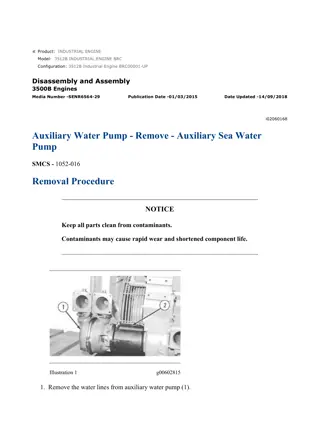
w 2/14(W) NOTICE Keep all parts clean from contaminants. Contaminants may cause rapid wear and shortened component life. Disassemble the Check Valve Note: If the hose assembly is leaking, the entire hose assembly must be replaced. Illustration 1 g01056041 1. Remove hose assembly (1) from the body of check valve (2) . https://127.0.0.1/sisweb/sisweb/techdoc/techdoc_print_page.jsp?returnurl=/sisweb/siswe... 2022/5/5
w 3/14(W) Illustration 2 g00714974 Personal injury can result from parts and/or covers under spring pressure. Spring force will be released when covers are removed. Be prepared to hold spring loaded covers as the bolts are loosened. 2. Use Tooling (E) in order to remove retainer (3) from the body of check valve (2) . 3. Remove spring (4) and disc (5) from the body of check valve (2) . Disassemble the Pump https://127.0.0.1/sisweb/sisweb/techdoc/techdoc_print_page.jsp?returnurl=/sisweb/siswe... 2022/5/5
https://www.ebooklibonline.com Hello dear friend! Thank you very much for reading. Enter the link into your browser. The full manual is available for immediate download. https://www.ebooklibonline.com
w 4/14(W) Illustration 3 g01055763 1. Remove bolts (6) in order to remove cover (7) . Illustration 4 g01055766 2. Remove O-ring seal (8) from cover (7) . Illustration 5 g01055768 3. Remove port plate (9) . https://127.0.0.1/sisweb/sisweb/techdoc/techdoc_print_page.jsp?returnurl=/sisweb/siswe... 2022/5/5
w 5/14(W) Illustration 6 g01055769 4. Remove nut (10) and the washer. Illustration 7 g01055770 5. Use Tooling (A) in order to remove impeller (11) . https://127.0.0.1/sisweb/sisweb/techdoc/techdoc_print_page.jsp?returnurl=/sisweb/siswe... 2022/5/5
w 6/14(W) Illustration 8 g01055773 6. Remove bolts (12) from body (13) . Note: Ring (14) and port plate (15) will remain inside when the body is removed. Illustration 9 g01055775 7. Use Tooling (J) in order to remove body (13) . Illustration 10 g01055781 8. Remove O-ring seal (16) from body (13) . https://127.0.0.1/sisweb/sisweb/techdoc/techdoc_print_page.jsp?returnurl=/sisweb/siswe... 2022/5/5
w 7/14(W) Illustration 11 g01055783 9. Remove ring (14) and port plate (15) from body (13) . Illustration 12 g01055786 10. Remove key (17) and shim (18) from shaft (19) . Illustration 13 g01055789 11. Bend the tabs of lockwasher (20) away from the flats of locknut (21) . https://127.0.0.1/sisweb/sisweb/techdoc/techdoc_print_page.jsp?returnurl=/sisweb/siswe... 2022/5/5
w 8/14(W) Illustration 14 g00705829 12. Hold the driven end of the shaft with Tooling (B) . Use Tooling (C) in order to loosen the locknut. Remove the locknut and the lockwasher from the shaft. Use a new lockwasher upon assembly. Illustration 15 g01055791 13. Use Tooling (A) in order to remove impeller (22) . https://127.0.0.1/sisweb/sisweb/techdoc/techdoc_print_page.jsp?returnurl=/sisweb/siswe... 2022/5/5
w 9/14(W) Illustration 16 g01055793 14. Place body (23) in the downward position. Remove bolts and washers (24) that attach bearing housing (25) to the body. Illustration 17 g01055795 15. Use Tooling (K) in order to force bearing housing (25) from body (23) . Illustration 18 g01055796 https://127.0.0.1/sisweb/sisweb/techdoc/techdoc_print_page.jsp?returnurl=/sisweb/siswe... 2022/5/5
w 10/14(W) Illustration 19 g01055798 16. Use Tooling (D) and a suitable press in order to remove the stationary segment of ceramic seal (26) from body (23) . Illustration 20 g01055799 17. Remove ring (27) and the rotating segment of ceramic seal (28) from shaft (19) . https://127.0.0.1/sisweb/sisweb/techdoc/techdoc_print_page.jsp?returnurl=/sisweb/siswe... 2022/5/5
w 11/14(W) Illustration 21 g01055802 18. Use an allen wrench to loosen the screws that hold ring (29) to shaft (19) . Remove the ring. Illustration 22 g01055803 19. Remove O-ring seal (30) from shaft (19) . Illustration 23 g01055804 20. Place bearing housing (25) in a vise with the driven end of the shaft in the upward position. Use Tooling (E) in order to remove retaining ring (31) . NOTICE Do not allow the shaft to fall when the shaft is removed from the bearing housing. https://127.0.0.1/sisweb/sisweb/techdoc/techdoc_print_page.jsp?returnurl=/sisweb/siswe... 2022/5/5
w 12/14(W) Illustration 24 g01055806 21. Place bearing housing (25) and shaft (19) in a suitable press. Orient the impeller end of the shaft in the upward position. Press the shaft out of the bearing housing. Illustration 25 g01055810 22. Place the shaft in a vise. Orient the driven end of the shaft in the upward position. Use Tooling (F) in order to remove nut (32) (not shown) from the shaft. Illustration 26 g01055815 https://127.0.0.1/sisweb/sisweb/techdoc/techdoc_print_page.jsp?returnurl=/sisweb/siswe... 2022/5/5
w 13/14(W) 23. Place shaft (19) and bearing (33) in a suitable press. Orient the driven end of the shaft in the upward position. Press the shaft out of the bearing. Illustration 27 g01055814 24. Remove collar (34) from bearing housing (25) . Illustration 28 g01055816 25. Use Tooling (G) in order to remove oil seal (35) from bearing housing (25) . https://127.0.0.1/sisweb/sisweb/techdoc/techdoc_print_page.jsp?returnurl=/sisweb/siswe... 2022/5/5
w 14/14(W) Illustration 29 g01055817 26. Use Tooling (E) in order to remove retaining ring (36) from bearing housing (25) . 27. Remove bearing (37) from bearing housing (25) . Illustration 30 g01055821 28. Use Tooling (H) in order to remove bearing race (38) from bearing housing (25) . https://127.0.0.1/sisweb/sisweb/techdoc/techdoc_print_page.jsp?returnurl=/sisweb/siswe... 2022/5/5
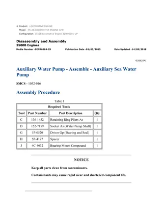
w 1/12(W) Product: INDUSTRIAL ENGINE Model: 3512B INDUSTRIAL ENGINE BR2 Configuration: 3512B Industrial Engine BR200001-UP Disassembly and Assembly 3500B Engines Media Number -UENR0181-11 Publication Date -01/09/2018 Date Updated -14/09/2018 i02062541 Auxiliary Water Pump - Assemble - Auxiliary Sea Water Pump SMCS - 1371-016 Assembly Procedure Table 1 Required Tools Tool Part Number Part Description Qty C 136-1452 Retaining Ring Pliers As 1 D 152-7159 Socket As (Water Pump Shaft) 1 G 1P-0520 Driver Gp (Bearing and Seal) 1 H 5P-4197 Spacer 1 J 4C-4032 Bearing Mount Compound 1 NOTICE Keep all parts clean from contaminants. Contaminants may cause rapid wear and shortened component life. https://127.0.0.1/sisweb/sisweb/techdoc/techdoc_print_page.jsp?returnurl=/sisweb/siswe... 2022/5/5
w 2/12(W) Illustration 1 g01057093 1. Place shaft (21) and bearing (25) in a suitable press. Make sure that the serial number on the bearing is toward the driven end of the shaft. Insert the driven end of the shaft into the bearing. Press the shaft into the bearing until the shoulder of the shaft contacts the bearing. Illustration 2 g01057051 2. Install spacer (24), lock ring (23), and nut (22) onto the end of shaft (21). Place the shaft into a vise with the bearing upward. Illustration 3 g01057048 3. Use Tooling (D) in order to tighten nut (22) to a torque of 167 33 N m (125 25 lb ft). https://127.0.0.1/sisweb/sisweb/techdoc/techdoc_print_page.jsp?returnurl=/sisweb/siswe... 2022/5/5
w 3/12(W) Illustration 4 g01057045 4. Place shaft (21) in a vise. Bend a tab of lock ring (23) into a slot of nut (22). Illustration 5 g01057103 Illustration 6 g01057060 5. Use a suitable press and Tooling (G) in order to install bearing race (29) into bearing housing (16). https://127.0.0.1/sisweb/sisweb/techdoc/techdoc_print_page.jsp?returnurl=/sisweb/siswe... 2022/5/5
w 4/12(W) Illustration 7 g01057115 6. Use a suitable press and Tooling (H) in order to install the shaft and bearing (25) into bearing housing (16). Illustration 8 g01057118 7. Use Tooling (C) in order to install retaining ring (20) into bearing housing (16). Make sure that the side of the ring with the bevel is upward. After the ring is installed, strike the ring with a punch in order to ensure that the ring is properly seated. Illustration 9 g01057120 https://127.0.0.1/sisweb/sisweb/techdoc/techdoc_print_page.jsp?returnurl=/sisweb/siswe... 2022/5/5
w 5/12(W) 8. Place bearing housing (16) and shaft (21) into a vise with the impeller end of the shaft in the upward position. Place bearing (28) into position with the serial number in the upward position. Use a hammer and a brass driver to install the bearing into the bearing housing. Alternatively, use a suitable press with an appropriate sleeve to press the bearing into the housing. Illustration 10 g01057123 9. Use Tooling (C) in order to install retaining ring (27) into bearing housing (16). After the retaining ring is installed, strike the ring with a punch in order to ensure that the ring is properly seated. Illustration 11 g01057128 10. Lubricate oil seal (26) with a solution of water and five percent soap. Install the oil seal into bearing housing (16). https://127.0.0.1/sisweb/sisweb/techdoc/techdoc_print_page.jsp?returnurl=/sisweb/siswe... 2022/5/5
w 6/12(W) Illustration 12 g01057132 11. Thoroughly clean shaft (21) and collar (18) with solvent. Apply Tooling (J) to the inside diameter of the collar. Install the collar onto the shaft. Rotate the collar for 180 degrees in both directions. Allow the compound to cure for 30 minutes. Illustration 13 g01057040 12. Install O-ring seal (19) over collar (18). Illustration 14 g00690988 13. Install ring (17) over the O-ring seal. Compress the O-ring seal with ring (17). Maintain approximately 490 45 N (110 10 lb) of pressure on ring (17) and use an allen wrench in https://127.0.0.1/sisweb/sisweb/techdoc/techdoc_print_page.jsp?returnurl=/sisweb/siswe... 2022/5/5
w 7/12(W) order to tighten the screws to a torque of 0.9 0.1 N m (7.97 0.10 lb in). After the screws are tightened, use a small center punch to peen the threads in the ring. Illustration 15 g01057139 14. Place drive housing (15) on blocks. Install bearing housing (16) onto the body. Attach the bearing housing to the body with washers and bolts (14). Note: Carefully inspect the surface of the ceramic seal. If the surface is cracked or scratched, discard the seal and obtain a new seal for installation. Ensure that the faces of the seal are clean. Illustration 16 g01057143 15. Orient the impeller end of shaft (21) to the upward position. Lubricate the stationary segment of the ceramic seal with a solution of water and five percent soap. Place the side of the segment with the bevel in the downward position. Use hand pressure in order to install the segment into drive housing (15). After the seal is installed, wipe the surface dry. https://127.0.0.1/sisweb/sisweb/techdoc/techdoc_print_page.jsp?returnurl=/sisweb/siswe... 2022/5/5
w 8/12(W) Illustration 17 g01057146 16. Lubricate the rotating segment of ceramic seal (13) with a solution of water and five percent soap. Orient the side of the segment with the spring to the upward position. Use hand pressure in order to install the rotating segment of ceramic seal (13) onto the stationary segment of the ceramic seal. After the seal is installed, wipe the surface dry. Illustration 18 g01057149 17. Lubricate port plate (11) with a solution of water and five percent soap. Align the tabs of the port plate with the notches in the body. Install the port plate into drive housing (15). https://127.0.0.1/sisweb/sisweb/techdoc/techdoc_print_page.jsp?returnurl=/sisweb/siswe... 2022/5/5
w 9/12(W) Illustration 19 g01057151 18. Determine the thickness of the shims for the impeller. The shims will be used in order to obtain a clearance of 0.18 to 0.23 mm (0.007 to 0.009 inch) on each side of the impeller. Place a straight edge on the face of the port plate (11) across the opening for shaft (21). Use a feeler gauge to measure Dimension (X) between the shoulder of the shaft and the face of the port plate. The correct thickness of the shims is Dimension (X) plus the specification of the clearance. Table 2 is an example of the calculation. Table 2 Example of the Calculation for Determining the Thickness of the Shims Dimension (X) Clearance Specification Thickness of the Shims 0.56 mm (0.022 inch) 0.20 mm (0.008 inch) 0.76 mm (0.03 inch) + = In the example, the proper thickness for the shims is 0.76 mm (0.030 inch). https://127.0.0.1/sisweb/sisweb/techdoc/techdoc_print_page.jsp?returnurl=/sisweb/siswe... 2022/5/5
Suggest: For more complete manuals. Please go to the home page. https://www.ebooklibonline.com If the above button click is invalid. Please download this document first, and then click the above link to download the complete manual. Thank you so much for reading
w 10/12(W) Illustration 20 g01057154 19. Install spacer (12) (not shown). Install shims (8). Install key (8A). Note: The spacer and the shims will protrude slightly above the port plate. This is normal. When the impeller is installed, the spring in the ceramic seal will be compressed and the spacer and the shims will be pushed down. Note: The impeller has threaded holes for the puller. Install the impeller with the holes toward the outside. Illustration 21 g01057157 20. Use a suitable press to install impeller (7) onto the shaft. Be sure to support the shaft with a jack and/or blocks. After the impeller is installed, rotate the impeller in order to make sure that the impeller does not rub. https://127.0.0.1/sisweb/sisweb/techdoc/techdoc_print_page.jsp?returnurl=/sisweb/siswe... 2022/5/5
w 11/12(W) Illustration 22 g00690890 21. Install the washer. Thoroughly clean the threads of the shaft and nut (6) with solvent. Apply Tooling (J) to the threads of nut (6). Install the nut. Tighten the nut to a torque of 155 20 N m (115 15 lb ft). Install the cotter pin in order to secure the nut. Illustration 23 g01057162 22. Install ring (10). Ensure that O-ring seal (9) is in good condition. Install O-ring seal (9). Illustration 24 g00603007 23. Lubricate port plate (5) with a solution of water and five percent soap. Install the port plate into body (4). https://127.0.0.1/sisweb/sisweb/techdoc/techdoc_print_page.jsp?returnurl=/sisweb/siswe... 2022/5/5
https://www.ebooklibonline.com Hello dear friend! Thank you very much for reading. Enter the link into your browser. The full manual is available for immediate download. https://www.ebooklibonline.com


