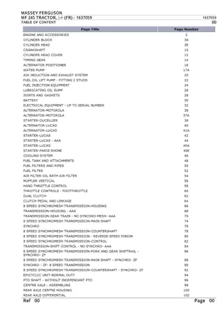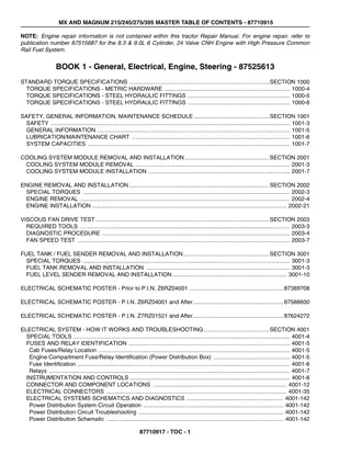
Caterpillar Cat 245 EXCAVATOR (Prefix 84X) Service Repair Manual Instant Download
Please open the website below to get the complete manualnn// n
Download Presentation

Please find below an Image/Link to download the presentation.
The content on the website is provided AS IS for your information and personal use only. It may not be sold, licensed, or shared on other websites without obtaining consent from the author. Download presentation by click this link. If you encounter any issues during the download, it is possible that the publisher has removed the file from their server.
E N D
Presentation Transcript
Service Repair Manual Model 245EXCAVATOR
245 EXCAVATOR 84X00001-UP (MACHINE) POWERED BY 3406 ENGINE(HEB... 1/26 Shutdown SIS Previous Screen Product: EXCAVATOR Model: 245 EXCAVATOR 84X Configuration: 245 EXCAVATOR 84X00001-UP (MACHINE) POWERED BY 3406 ENGINE Disassembly and Assembly 245 EXCAVATOR VEHICLE SYSTEMS Media Number -SENR7339-02 Publication Date -01/01/1983 Date Updated -12/10/2001 Swing Drive SMCS - 5459-11; 5459-12; 5459-15; 5459-16 Remove Swing Drive start by: a) remove swing motor Do not disconnect any oil lines from the implement circuits until all oil pressure in the implement circuits has been released. 1. To release the oil pressure in the implement circuits, remove five plugs (2) and slowly loosen plugs (1) until the oil pressure is released. Tighten plugs (1) and install plugs (2). 2. Remove the oil from the hydraulic tank. The capacity of the tank is approximately 110 U.S. gal. (416.4 liter). https://127.0.0.1/sisweb/sisweb/techdoc/techdoc_print_page.jsp?returnurl=/sis... 2019/10/9
245 EXCAVATOR 84X00001-UP (MACHINE) POWERED BY 3406 ENGINE(HEB... 2/26 3. Disconnect the swing brake control linkage (6) from brake. 4. Remove hydraulic line (5). Disconnect oil line (3) from the manifold on the oil filters. 5. Disconnect five oil lines (4) from five oil tubes (7). 6. Disconnect the five oil tubes (7) from the main control valves. Remove oil tubes (7) and support (8) as a unit. 7. Disconnect oil line (11) at support (12). Remove the bolt that holds support (12) to the swing drive. 8. Remove bolts (10) that hold manifold (9) to the bracket. 9. Remove the bolts that hold the swing drive to the frame with tool (A). 10. Install three 1/2" - 13 NC forged eyebolts (14). Fasten a hoist and remove the swing drive (13). Weight of swing drive is 1650 lb. (743 kg). NOTE: The case has two holes for forcing screws. Forcing screws can be needed to loosen the case from the upper frame. Install Swing Drive https://127.0.0.1/sisweb/sisweb/techdoc/techdoc_print_page.jsp?returnurl=/sis... 2019/10/9
https://www.ebooklibonline.com Hello dear friend! Thank you very much for reading. Enter the link into your browser. The full manual is available for immediate download. https://www.ebooklibonline.com
245 EXCAVATOR 84X00001-UP (MACHINE) POWERED BY 3406 ENGINE(HEB... 3/26 1. Put 2P2506 Anti-Seize Compound on the outside of pinion gear cage and bore (1) in the frame. 2. Use three 1/2" - 13 NC forged eyebolts to fasten a hoist and put the swing drive into position in the frame. NOTE: Turn the brake drum on the swing drive to get pinion and swing gear in alignment. 3. Install the fourteen bolts (2) that hold the swing drive to the frame. Tighten the fourteen bolts to a torque of 880 80 lb.ft. (1190 110 N m) with tool (A). 4. Install the bolts that hold manifold (5) to bracket (3). 5. Put support (4) in position on the swing drive and install the bolt that holds it. 6. Connect oil line (6) as shown. 7. Connect swing brake control linkage (11). https://127.0.0.1/sisweb/sisweb/techdoc/techdoc_print_page.jsp?returnurl=/sis... 2019/10/9
245 EXCAVATOR 84X00001-UP (MACHINE) POWERED BY 3406 ENGINE(HEB... 4/26 8. Install oil tubes (7) and support as a unit. Connect oil lines (8) to oil tubes (7). 9. Connect oil line (9) to the manifold on the oil filters. 10. Install the oil line from the manifold on the oil filters to the flow control valve (10) for the oil cooler. 11. Fill the hydraulic tank with oil to the correct level after the swing motor is installed. end by: a) install swing motor Disassemble Swing Drive https://127.0.0.1/sisweb/sisweb/techdoc/techdoc_print_page.jsp?returnurl=/sis... 2019/10/9
245 EXCAVATOR 84X00001-UP (MACHINE) POWERED BY 3406 ENGINE(HEB... 5/26 start by: a) remove swing drive motor b) remove swing drive c) remove swing drive brake https://127.0.0.1/sisweb/sisweb/techdoc/techdoc_print_page.jsp?returnurl=/sis... 2019/10/9
245 EXCAVATOR 84X00001-UP (MACHINE) POWERED BY 3406 ENGINE(HEB... 6/26 1. Fasten a hoist and put the swing drive in position on tooling (A). The weight of the swing drive is 1650 lb. (743 kg). 2. Remove lubrication line (1) from the swing drive. Remove the plug from the bottom of the case assembly and drain the oil from the swing drive. 3. Remove bolts from bearing cage (2). Install two 1/2" - 13 NC forcing screws (3) and remove bearing cage and shims (4). 4. Use tooling (B) and remove the bearing cup from cage (2). Remove O-ring seal (5) from the bearing cage (2). 5. Remove the bolts from cover (6) and use two 5/8" - 11 NC forcing screws (7) to loosen the cover from the dowels on the case assembly. 6. Fasten a hoist and remove cover (6). The weight of the cover is 270 lb. (122 kg). https://127.0.0.1/sisweb/sisweb/techdoc/techdoc_print_page.jsp?returnurl=/sis... 2019/10/9
245 EXCAVATOR 84X00001-UP (MACHINE) POWERED BY 3406 ENGINE(HEB... 7/26 7. Remove the bolts that hold cage (8) and use two 1/2" - 13 NC forcing screws to loosen it from the cover. Remove cage (8) and the shims from the cover. 8. Use tooling (B) to remove the bearing cup from cage (8). Remove O-ring seal (9) from cage (8). 9. Use tooling (C) to push the lip type seal out of cage (8) through the bore for the bearing cup. 10. Turn cover (6) over and use tooling (B) to remove bearing cup (10). 11. Remove pinion (11) from the case assembly. https://127.0.0.1/sisweb/sisweb/techdoc/techdoc_print_page.jsp?returnurl=/sis... 2019/10/9
245 EXCAVATOR 84X00001-UP (MACHINE) POWERED BY 3406 ENGINE(HEB... 8/26 12. Pull bushing (15) and spring assembly (14) from the bottom of pinion (11) by hand. 13. Use tooling (D) to remove bearing cones (12) and (13) from pinion (11). NOTICE When cover (16) is removed the pump assembly can fall out of the case assembly. Remove cover (16) slowly. 14. Remove the bolts and remove cover (16) and the pump assembly from the bottom of the case assembly. 15. Remove bushing (18) from pump body (17). 16. Remove plate (19) and rotor (20) from pump body (17). https://127.0.0.1/sisweb/sisweb/techdoc/techdoc_print_page.jsp?returnurl=/sis... 2019/10/9
245 EXCAVATOR 84X00001-UP (MACHINE) POWERED BY 3406 ENGINE(HEB... 9/26 NOTE: Make a replacement of the pump as a unit if needed. The parts can not be ordered separately. 17. Remove gear (21) from the case assembly. 18. Use tooling (D) to remove the bearing cones from each end of gear (21). 19. Remove the bolts that hold cage (22) to the bottom of the case assembly. Use two 1/2"-13 NC forcing screws to loosen cage (22) and remove it from the case assembly. 20. Use tooling (E) to remove the bearing cup from cage (22). Remove the O-ring seal from around the cage. 21. Install a 5/8"-11 NC forged eyebolt in the case assembly. Install a strap through one of the holes in the output gear and around the eyebolt to prevent rotation of the output gear. https://127.0.0.1/sisweb/sisweb/techdoc/techdoc_print_page.jsp?returnurl=/sis... 2019/10/9
245 EXCAVATOR 84X00001-UP (MACHINE) POWERED BY 3406 ENGINE(H... 10/26 22. Remove the lockwire from the three bolts (25) that hold lower pinion (24) in place and loosen the bolts. Do not remove bolts (25) at this time. 23. Remove the lockwire from bolts (23) and remove them from the shaft. Use the strap and eyebolt again as shown to prevent rotation of the output gear. 24. Remove retainer (26) and shims (27) from the end of the shaft. 25. Fasten a hoist to output gear (28) as shown. Pull gear (29) back against the case assembly for clearance to remove gear (28). Remove gear (28) from the case assembly. The weight of gear (28) is 150 lb. (68 kg). https://127.0.0.1/sisweb/sisweb/techdoc/techdoc_print_page.jsp?returnurl=/sis... 2019/10/9
245 EXCAVATOR 84X00001-UP (MACHINE) POWERED BY 3406 ENGINE(H... 11/26 26. Install retainer (26) and bolts (23) on the shaft after gear (28) is removed. 27. Install a 1/2"-13 NC forged eyebolt in gear (29). Fasten a hoist and remove gear (29) from the case assembly. The weight of gear (29) is 100 lb. (45 kg). 28. Use tooling (D) to remove the bearing cones from each end of gear (29). 29. Remove the housing from tool (A). Turn the housing over so pinion (24) is up. 30. Remove the three bolts and retainer that hold pinion (24) in place. Fasten a hoist and remove pinion (24). Weight of the pinion is 56 lb. (25 kg). 31. Remove retainer assembly (30) and one half of the Duo-Cone seal from the shaft. The Duo-Cone seal can stay on the shaft after retainer assembly (30) is removed. 32. Remove one half of the Duo-Cone seal and the Duo-Cone seal retainer (31) from cage (32). https://127.0.0.1/sisweb/sisweb/techdoc/techdoc_print_page.jsp?returnurl=/sis... 2019/10/9
245 EXCAVATOR 84X00001-UP (MACHINE) POWERED BY 3406 ENGINE(H... 12/26 33. Remove one half of the Duo-Cone seal (33) from retainer assembly (30), if it was removed with the retainer. 34. Turn the housing over so cage (32) is down and put the case assembly and cage in a press as shown. 35. Put supports under cage (32). Make sure retainer (26) is installed on pinion shaft (34). The pinion shaft can fall out of the case assembly when shaft (34) is pushed out of bearing cone (35) if retainer (26) is not installed. 36. Use the press and push shaft (34) out of bearing cone (35). The application of heat to bearing cone (35) can be needed to remove shaft (34) from the bearing cone. 37. Remove the housing and pinion shaft from the press. 38. Put the housing on its side. Remove the retainer and bearing cone (36) from the end of the shaft. https://127.0.0.1/sisweb/sisweb/techdoc/techdoc_print_page.jsp?returnurl=/sis... 2019/10/9
245 EXCAVATOR 84X00001-UP (MACHINE) POWERED BY 3406 ENGINE(H... 13/26 39. Fasten a hoist and remove pinion shaft (34) from the housing. Weight of the shaft is 190 lb. (86 kg). TYPICAL EXAMPLE 40. Turn the shaft over and put it in the position shown. Use tools (J) to hold the shaft in position against tool (A). 41. Use tooling (F) to remove bearing cone (37) from the pinion shaft. NOTE: After a swing gear or swing pinion failure, the pinion shaft must be checked to make sure it is straight. Hold the pinion shaft between machine centers and check the shaft with a dial indicator against the lower bearing diameter. The total indicator reading at this location must not be more than .003 in. (0.08 mm). If it is, install a new shaft. 42. Use tooling (B) to remove bearing cups (38) and (39) from the case assembly. 43. Use tooling (G) to remove bearing cup (40) from the case assembly. https://127.0.0.1/sisweb/sisweb/techdoc/techdoc_print_page.jsp?returnurl=/sis... 2019/10/9
245 EXCAVATOR 84X00001-UP (MACHINE) POWERED BY 3406 ENGINE(H... 14/26 44. Use tooling (H) to remove bearing cup (41) from cage (32). NOTE: After a failure, check the bearing bore in the cage (32) to see that the bore is still round. The bore in the cage must be 9.2475 .0015 in. (234.887 .038 mm). If not, install a new cage. 45. Remove the bolts that hold cage (32) to the case assembly. Fasten a hoist and remove cage (32) from the case assembly. The weight of cage (32) is 120 lb. (54 kg). 46. Remove the O-ring seal from around cage (32). NOTE: Thoroughly clean all parts to be used again at assembly. https://127.0.0.1/sisweb/sisweb/techdoc/techdoc_print_page.jsp?returnurl=/sis... 2019/10/9
245 EXCAVATOR 84X00001-UP (MACHINE) POWERED BY 3406 ENGINE(H... 15/26 Assemble Swing Drive https://127.0.0.1/sisweb/sisweb/techdoc/techdoc_print_page.jsp?returnurl=/sis... 2019/10/9
245 EXCAVATOR 84X00001-UP (MACHINE) POWERED BY 3406 ENGINE(H... 16/26 1. Install O-ring seal (2) on cage (1) and put clean oil on it. 2. Fasten a hoist and put cage (1) in position on the case assembly. Install bolts (4) and tighten them to a torque of 265 35 lb.ft. (360 47 N m). 3. Lower the temperature of bearing cup (3) to -103 9 F (-75 5 C) and install it in cage (1) as shown. After bearing cup (3) is at ambient (atmospheric) temperature again, make sure it is tight against the shoulder in cage (1). https://127.0.0.1/sisweb/sisweb/techdoc/techdoc_print_page.jsp?returnurl=/sis... 2019/10/9
245 EXCAVATOR 84X00001-UP (MACHINE) POWERED BY 3406 ENGINE(H... 17/26 4. Turn the case assembly and cage over. Lower the temperature of bearing cups (5), (6) and (7) to - 103 9 F (-75 5 C) and install them in the case assembly as shown. After the bearing cups are at ambient (atmospheric) temperature again, make sure they are tight against the shoulders in the case assembly. 5. Put the pinion shaft (8) against tool (B) with the pinion end of the shaft up as shown. Use tools (C) to hold the shaft in place. Put 2P2506 Anti-Seize Compound on the surface of the shaft for the bearing cone and on the pinion gear splines. NOTICE Do not install bearing cone (9) on the shaft more than 6 1/2 inches (16.5 cm) from end of shaft. The bearing cone will be pushed into the correct position when the pinion gear is installed. 6. Heat bearing cone (9) to a maximum temperature of 275 F (135 C). Install the bearing cone in position on shaft as shown. 7. Use tool (A) to install each half of the Duo-Cone seal in retainer (11) and retainer assembly (10). NOTE: The rubber seals and all surfaces that make contact with the seals must be clean and dry. After installation of seals, put oil on the contact surfaces of the metal seals. 8. Install the O-ring seal on retainer (11) and put clean oil on it. Install retainer (11) on the pinion shaft as shown. https://127.0.0.1/sisweb/sisweb/techdoc/techdoc_print_page.jsp?returnurl=/sis... 2019/10/9
245 EXCAVATOR 84X00001-UP (MACHINE) POWERED BY 3406 ENGINE(H... 18/26 9. Install retainer assembly (10) on the pinion shaft as shown until the spacer in the retainer assembly makes contact with the inner race of bearing cone (9). Make sure the O-ring seal is installed in the top of the retainer assembly and has clean oil on it. NOTE: A larger diameter O-ring seal is needed for later retainer assemblies. 10. Fasten a hoist and install pinion (14) on the shaft. Make sure the spline counterbore (seal groove) is toward the end of the shaft when the pinion is installed. 11. Put retainer (12) in position on the pinion and install the bolts to hold it to the pinion shaft. NOTICE New bolts and washers must be used. If retainer (12) is cupped (bent) or shows wear, install a new retainer. 12. Push the pinion into position on the shaft with retainer (12) and the three bolts. The pinion is in the correct position when the retainer (12) is against the end of the shaft. 13. Remove the bolts and retainer (12). Install O-ring seal (13) in the pinion counterbore area and put clean oil on it. Install the retainer, bolts and washers. Tighten the three bolts to a torque of 200 20 lb.ft. (270 25 N m). 14. Install the lockwire in the three bolts. https://127.0.0.1/sisweb/sisweb/techdoc/techdoc_print_page.jsp?returnurl=/sis... 2019/10/9
245 EXCAVATOR 84X00001-UP (MACHINE) POWERED BY 3406 ENGINE(H... 19/26 15. Put the pinion shaft on blocks on tool (B) so the pinion is on the blocks. The pinion shaft will be in its normal position. 16. Put 2P2506 Anti-Seize Compound on the surfaces for the upper bearing cone and the shaft splines. 17. Fasten a hoist to case (15) and lower the case over the pinion shaft and on to tool (B). Put the holes in the retainer (11) in alignment with the dowel pins in the cage (1) as the case is lowered on to the pinion shaft. 18. Heat bearing cone (17) to a maximum temperature of 275 F (135 C). Install the bearing cone on pinion shaft (16). Let bearing cone (17) become cool before adjustment of the bearing preload is made. 19. Heat the two bearing cones for gear (18) to a maximum temperature of 275 F (135 C) and install them on each end of gear (18). Make sure the bearing cones are tight against the gear when installed. 20. Fasten a hoist to gear (18) with a 1/2"-13 NC forged eyebolt and put the gear in position in the case. 21. Fasten a hoist to output gear (20) and put the gear in position on the pinion shaft. The counterbore in the gear hub must be next to the bearing. 22. Install retainer (19) and three 5/8"-11 NC bolts 3 1/4" long. https://127.0.0.1/sisweb/sisweb/techdoc/techdoc_print_page.jsp?returnurl=/sis... 2019/10/9
245 EXCAVATOR 84X00001-UP (MACHINE) POWERED BY 3406 ENGINE(H... 20/26 23. Install a 5/8"-11 NC forged eyebolt in the case. Install a strap through output gear (20) and around the eyebolt so the gear will not turn. 24. Push gear (20) on the pinion shaft with the three 5/8"-11 NC bolts. Remove the longer bolts and install the correct bolts and washers. Tighten the three bolts until there is no axial play (end play). Then, tighten the three bolts in the retainer until the torque needed to turn the shaft slowly at a constant rpm is 10 2 lb.ft. (14 3 N m). (10 2 lb.ft. is the same as 120 24 lb.in.). NOTICE New bolts and washers must be used. If retainer (19) is cupped (bent) or shows wear, install a new retainer. 25. Measure the gap between the retainer assembly (10) and retainer (11) with a feeler gauge. The gap must be .12 .04 in. (3.0 1.0 mm). If the gap is not in this tolerance range, check the dimensions of the components as shown in Illustration B07507X1 on Page 155 to check the dimensions of the components so the correct replacement can be made. NOTICE Retainer (11) must be tight against the cage and retainer assembly (10) must be tight against the pinion gear when gap is measured. 26. Make adjustment to the output shaft bearings as follows: a) Move gear (18) to a position so it is not engaged in output gear (20). https://127.0.0.1/sisweb/sisweb/techdoc/techdoc_print_page.jsp?returnurl=/sis... 2019/10/9
Suggest: If the above button click is invalid. Please download this document first, and then click the above link to download the complete manual. Thank you so much for reading
245 EXCAVATOR 84X00001-UP (MACHINE) POWERED BY 3406 ENGINE(H... 21/26 b) Turn the output shaft with a torque wrench on one of the retainer bolts (21). Tighten the three bolts (21) in the retainer until the torque needed to turn the shaft slowly at a constant rpm is 50 5 lb.ft. (70 7 N m). c) Measure the distance between the end of the output shaft and outer surface of the retainer (19) with a depth gauge (D) through the hole in the retainer. Measure the thickness of the retainer (19). Then install shims that have a thickness the same as (equal to) the difference between the two measurements. d) Install the retainer, bolts and washers. Tighten the bolts to a torque of 200 20 lb.ft. (270 25 N m). e) Turn the shaft not less than five turns. Check the rotation torque again to be sure the output shaft will turn with a torque of 50 5 lb.ft. (70 7 N m). f) If the rotation torque is not correct, add or remove shims as necessary. If the measured torque is above specification, shims must be added. If the torque is below specification, shims must be removed. NOTICE If the rotation torque is above specification, and it becomes necessary to move the shaft down in bearing cone (17) to loosen the preload, remove bolts (22), retainer (19) and the shims and hit the end of the shaft with a rubber hammer. g) Install lockwire in the bolts (22). https://127.0.0.1/sisweb/sisweb/techdoc/techdoc_print_page.jsp?returnurl=/sis... 2019/10/9
https://www.ebooklibonline.com Hello dear friend! Thank you very much for reading. Enter the link into your browser. The full manual is available for immediate download. https://www.ebooklibonline.com

