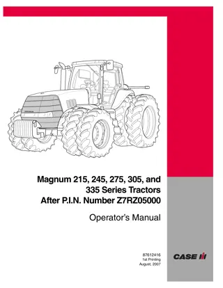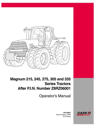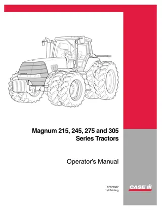
Caterpillar Cat 245 EXCAVATOR (Prefix 82X) Service Repair Manual Instant Download
Please open the website below to get the complete manualnn//
Download Presentation

Please find below an Image/Link to download the presentation.
The content on the website is provided AS IS for your information and personal use only. It may not be sold, licensed, or shared on other websites without obtaining consent from the author. Download presentation by click this link. If you encounter any issues during the download, it is possible that the publisher has removed the file from their server.
E N D
Presentation Transcript
Service Repair Manual Model 245EXCAVATOR
245 EXCAVATOR 82X00001-UP (MACHINE) POWERED BY 3406 ENGINE(SEB... 1/22 Shutdown SIS Previous Screen Product: EXCAVATOR Model: 245 EXCAVATOR 82X Configuration: 245 EXCAVATOR 82X00001-UP (MACHINE) POWERED BY 3406 ENGINE Disassembly and Assembly 245 EXCAVATOR VEHICLE SYSTEMS Media Number -SENR7339-02 Publication Date -01/01/1983 Date Updated -12/10/2001 Swing And Track Motors SMCS - 5058-16; 5058-15 Disassemble Swing And Track Motors start by: a) remove swing motor b) remove track motors https://127.0.0.1/sisweb/sisweb/techdoc/techdoc_print_page.jsp?returnurl=/sis... 2019/10/8
245 EXCAVATOR 82X00001-UP (MACHINE) POWERED BY 3406 ENGINE(SEB... 2/22 1. Fasten adapter and bracket (1), part of tooling (A), to the track motor as shown with three 3/4"-10 NC bolts 21/4 inches long. Fasten a hoist and put the track motor in position on the engine stand of tooling (A). Weight of the track motor is 210 lb. (95 kg). 2. Loosen plugs (2) in the shuttle valve. Remove bolts (3) and shuttle valve (4) from the pump head. NOTE: On earlier machines the shuttle valve location is on the upper body. 3. Remove plugs (2), O-ring seals (5), balls (6) and pin (7) from the shuttle valve. Remove O-ring seals (8) and (9) from the shuttle valve. NOTE: On earlier machines there are stops behind plugs (2) with a ring and seal on each stop Use an 8-32 screw to pull the stops from the shuttle valve. 4. Bend the lock back and remove bolt (10), the lock and retainer from the shaft. https://127.0.0.1/sisweb/sisweb/techdoc/techdoc_print_page.jsp?returnurl=/sis... 2019/10/8
https://www.ebooklibonline.com Hello dear friend! Thank you very much for reading. Enter the link into your browser. The full manual is available for immediate download. https://www.ebooklibonline.com
245 EXCAVATOR 82X00001-UP (MACHINE) POWERED BY 3406 ENGINE(SEB... 3/22 5. Put identification on the pump head as to its location on the body for correct alignment at assembly. Remove bolts (11) and pump head (12) from the body. 6. Remove O-ring seal (13) from body (14). 7. Put identification on body (14) as to its location on the lower body. NOTICE Do not let the pump barrel fall when body (14) is removed. Install protective plate (B) on the pump barrel. Keep protective plate (B) on the pump barrel at all times to prevent damage to the face of the pump barrel. 8. Remove bolts (15) and body (14) from the lower body. https://127.0.0.1/sisweb/sisweb/techdoc/techdoc_print_page.jsp?returnurl=/sis... 2019/10/8
245 EXCAVATOR 82X00001-UP (MACHINE) POWERED BY 3406 ENGINE(SEB... 4/22 9. Remove O-ring seal (17) from the lower body. NOTE: It is not necessary to install the barrel over the same pistons at assembly so identification on the barrel and pistons is not necessary. 10. Carefully remove barrel (16) from the pistons. NOTE: It is necessary to remove tool (B) from the barrel to remove the snap ring and shaft (18). Install tool (B) on the barrel again as soon as shaft (18) is removed. 11. Use tool (C) to remove the snap ring that holds shaft (18) in place. Remove shaft (18) from the barrel. 12. Remove spring (20) and tube (19) from shaft (18). Earlier motors do not have spring (20). The spring on shaft (18) can cause injury if all the tension in the spring is not released before tool (D) is remove. To prevent injury be sure all the tension in the spring is released before tool (D) is removed from the shaft. https://127.0.0.1/sisweb/sisweb/techdoc/techdoc_print_page.jsp?returnurl=/sis... 2019/10/8
245 EXCAVATOR 82X00001-UP (MACHINE) POWERED BY 3406 ENGINE(SEB... 5/22 13. Use tool (D) and a 5/16" bolt at least 61/2 inches long with a nut and washers to put the spring in compression so the snap ring can be removed from the groove in shaft (18). Use tool (E) to remove the snap ring from the groove. Carefully loosen the bolt in tool (D) to release all the tension in the spring. Remove tool (D) after the tension in the spring is released. 14. Remove snap ring (23), retainer (22), races (21) and bearing (26), spring (24) and race (25) from shaft (18). 15. Use tool (F) to remove the snap ring that holds the bearing race on shaft (18). 16. Use tooling (G) as shown to remove race (27) from the end of shaft (18). https://127.0.0.1/sisweb/sisweb/techdoc/techdoc_print_page.jsp?returnurl=/sis... 2019/10/8
245 EXCAVATOR 82X00001-UP (MACHINE) POWERED BY 3406 ENGINE(SEB... 6/22 17. Use tool (H) to remove snap ring (28) from the barrel. 18. Use tooling (J) and a press to remove the bearing from the barrel (16). NOTICE Links (30) must be installed in the same inserts in drive plate (31) they are removed from so put identification on links (30) as to their location in drive plate (31). Be extra careful not to damage the highly finished surfaces of the pistons. 19. Use tool (C) to remove snap rings (29) that hold links (30) in position on drive plate (31). Remove the piston assemblies from the drive plate. NOTICE Pistons (32) must be installed on the same links they are removed from so put identification on the pistons and links. https://127.0.0.1/sisweb/sisweb/techdoc/techdoc_print_page.jsp?returnurl=/sis... 2019/10/8
245 EXCAVATOR 82X00001-UP (MACHINE) POWERED BY 3406 ENGINE(SEB... 7/22 20. Use tool (K) to remove snap ring (34) from piston (32). Remove piston (32), retainer (33), snap rings (34), (29) and retainer (35) from the link. Disassemble the remainder of the piston assemblies. 21. Remove the bolts that hold retainer (36) to the body and use screwdrivers in notches (37) to remove the retainer from the body. On earlier motors, two 5/16"-18 NC forcing screws can be used to remove the retainer. 22. Remove seal (38) and O-ring seal (39) from the retainer. 23. Fasten tool (L) to a work bench, over a hole that is 2.50 in. (63.5 mm) in diameter. 24. Use two 3/4"-10 NC forged eyebolts and fasten a hoist to body (42). Remove the body from the bracket of tooling (A). The weight of the body is 80 lb. (36 kg). 25. Put body (42) in position on tool (L) as shown. Make sure pin (40) is engaged with the notch (groove) on the outside diameter of drive plate (31). https://127.0.0.1/sisweb/sisweb/techdoc/techdoc_print_page.jsp?returnurl=/sis... 2019/10/8
245 EXCAVATOR 82X00001-UP (MACHINE) POWERED BY 3406 ENGINE(SEB... 8/22 26. Bend the tab of the lock from spanner nut (41). NOTICE When tool (M) is used to loosen the spanner nut, be sure the teeth on the spanner socket do not engage in the teeth of the lock. 27. Use tool (M) to remove the spanner nut from the drive plate. 28. Remove shims (43) from the drive plate. https://127.0.0.1/sisweb/sisweb/techdoc/techdoc_print_page.jsp?returnurl=/sis... 2019/10/8
245 EXCAVATOR 82X00001-UP (MACHINE) POWERED BY 3406 ENGINE(SEB... 9/22 29. Put body (42) in a press with a support under the body so drive plate (31) can be pushed out the bottom of the body. Put tool (N) on the end of drive plate (31) and push the drive plate out of the body. Do not let the drive plate fall when it is free of the smaller bearing cone in body (42). 30. Remove the smaller bearing cone from body (42). 31. Use tooling (O) to remove the smaller bearing cup from body (42). 32. Use tooling (O) to remove the larger bearing cup from body (42). 33. Use a hammer and punch to push the roll pin in drive plate (31) into the joint assembly inside the drive plate. 34. Use tool group (J) and a press to push joint assembly (44) out of drive plate (31). Do not let the joint assembly fall when it is free of the drive plate. 35. Remove the roll pin from joint assembly (44). https://127.0.0.1/sisweb/sisweb/techdoc/techdoc_print_page.jsp?returnurl=/sis... 2019/10/8
245 EXCAVATOR 82X00001-UP (MACHINE) POWERED BY 3406 ENGINE(S... 10/22 36. Use tooling (P) and a press to push drive plate (31) out of bearing cone (45). The pins of tooling (P) are installed through the holes in drive plate (31) as support for bearing cone (45). 37. If necessary, use a press to push inserts (46) out of the drive plate. Assemble Swing And Track Motors 1. Thoroughly clean all parts before assembly. Put a small amount of hydraulic oil on all parts before assembly. https://127.0.0.1/sisweb/sisweb/techdoc/techdoc_print_page.jsp?returnurl=/sis... 2019/10/8
245 EXCAVATOR 82X00001-UP (MACHINE) POWERED BY 3406 ENGINE(S... 11/22 2. Lower the temperature of (chill) the two bearing cups for body (1) for two hours minimum. 3. Install the two bearing cups in the body. NOTICE Do not turn the body over to install the second bearing cup until the first bearing cup is warm. 4. After the bearing cups are at ambient (atmospheric) temperature, put body (1) in a press. Use tool (A) and the press to put a force of 7 ton (63 kN) on the small bearing cup to push the bearing cup against its seat. 5. Turn the body over and use tool (B) and the press to put a force of 9 ton (81 kN) on the large bearing cup to push the bearing cup against its seat. 6. Lower the temperature of inserts (2) and use a press to install the inserts in drive plate (3). https://127.0.0.1/sisweb/sisweb/techdoc/techdoc_print_page.jsp?returnurl=/sis... 2019/10/8
245 EXCAVATOR 82X00001-UP (MACHINE) POWERED BY 3406 ENGINE(S... 12/22 7. Heat bearing cone (4) to a maximum temperature of 275 F (135 C) for a minimum of one hour. Install the bearing cone on drive plate (3). NOTICE Push on only the inner race of bearing cone (4). 8. After bearing cone (4) has become cool use tool (C), spacer (5) and a press to put a force of 9 ton (81 kN) on the bearing cone to push the bearing cone against its seat on drive plate (3). NOTE: The bearing cups and cone must be installed correctly to get a correct bearing adjustment when assembled. 9. Put joint assembly (6) in position inside the drive plate with pin hole (7) in alignment with the hole in the drive plate. Use tooling (D) and a 5/8"-11 NC bolt 5 1/2 in. long to pull the joint assembly into position. https://127.0.0.1/sisweb/sisweb/techdoc/techdoc_print_page.jsp?returnurl=/sis... 2019/10/8
245 EXCAVATOR 82X00001-UP (MACHINE) POWERED BY 3406 ENGINE(S... 13/22 10. Install pin (8) to hold joint assembly (6) in place. 11. Heat small bearing cone (9) to a maximum temperature of 275 F (135 C) for a minimum of one hour. Install the small bearing cone on the drive plate. 12. Install a 1"-14 NF bolt six inches long with a nut and washer on tooling (E). Use tooling (E) to make sure the small bearing cone is installed all of the way on the drive plate. 13. Fasten tool (F) to a work bench, over a hole that is 2.50 in. (63.5 mm) in diameter. 14. Put body (1) in position on tool (F). Make sure pin (10) is engaged with the notch (groove) on the outside diameter of the drive plate. https://127.0.0.1/sisweb/sisweb/techdoc/techdoc_print_page.jsp?returnurl=/sis... 2019/10/8
245 EXCAVATOR 82X00001-UP (MACHINE) POWERED BY 3406 ENGINE(S... 14/22 15. Install the spanner nut on the drive plate with the finished face down. Install a 5/16"-18 NC bolt 1/2 in. long in body (1). The bolt is used with tool (G) to turn the body. Install tool (G) with the correct socket on the 5/16 in. bolt so the centerline of tool (G) is toward the center of the body as shown. 16. Use tool (H) to tighten the spanner nut while body (1) is turned with tool (G). Tighten the spanner nut until the torque needed to keep body (1) in rotation is 4 to 9 lb.in. (0.4 to 1 N m). NOTE: Tool (G) is a lb.in. (N m) torque wrench that is 8 in. (20.3 cm) long. For other lb.in. torque wrenches, the correct torque indication can be found with this formula: C = A x T / A + B "C" is the torque wrench reading. "A" is the length of the torque wrench. "B" is the distance from the center of the wheel to the wheel stud. "T" is torque on bearings [T = 5 to 12 lb.in. (0.6 to 1.3 N m)]. 17. Hit the end of the drive plate with a soft faced hammer to push the bearing cone against the spanner nut. 18. Put the body in a vise with the drive plate in a horizontal position. 19. Install tooling (J) as shown to check the end clearance in the bearings. 20. Push on the handle of tooling (J) and turn the drive plate backward and forward in each direction. Put the indicator on zero. 21. Pull on the handle of tooling (J) and turn the drive plate backward and forward in each direction. The indicator will show the total end clearance. The end clearance must be .0005 to .002 in. (0.013 to 0.050 mm). NOTE: Steps 17 through 21 are done to check the bearing setting made in Step 16. https://127.0.0.1/sisweb/sisweb/techdoc/techdoc_print_page.jsp?returnurl=/sis... 2019/10/8
245 EXCAVATOR 82X00001-UP (MACHINE) POWERED BY 3406 ENGINE(S... 15/22 22. Find the thickness of the shim pack as follows: a) Use tool (K) to measure the distance from the end of drive plate (3) to the face of the inner race of bearing cone (9). b) Use tool (K) to measure the distance from the end of drive plate (3) to step (11) on the drive plate. c) Subtract the distance found in Step (a) from the distance found in Step (b). The difference will be the thickness of the shim pack. Measure the thickness of the shim pack with a micrometer. 23. Install shim pack (12) on the drive plate. 24. Install lock (13) on the drive plate. https://127.0.0.1/sisweb/sisweb/techdoc/techdoc_print_page.jsp?returnurl=/sis... 2019/10/8
245 EXCAVATOR 82X00001-UP (MACHINE) POWERED BY 3406 ENGINE(S... 16/22 25. Install spanner nut (14) on drive plate (3) with the finished face down. Use tool (H) to tighten the spanner nut to a torque of 400 lb.ft. (540 N m). 26. Check the torque needed to turn the body again as in Step 16. The torque must be the same. 27. When the correct values of end play and rotation torque are found, bend one ear of lock (13) to hold the spanner nut tight. 28. Fasten adapter and bracket (15), part of tooling (L), to body (1) as shown, with three 3/4"-10 NC bolts 2 1/4 inches long. Fasten a hoist and put the body in position on the engine stand of tooling (L). Weight of the body is 80 lb. (36 kg). 29. Install the lip type seal in retainer (17) with tool (D) and a 1"-14 NF bolt six inches long with a nut and washer. Install the seal with the lip up as shown. Install O-ring seal (16) on the retainer. Put clean oil on the seals. https://127.0.0.1/sisweb/sisweb/techdoc/techdoc_print_page.jsp?returnurl=/sis... 2019/10/8
245 EXCAVATOR 82X00001-UP (MACHINE) POWERED BY 3406 ENGINE(S... 17/22 30. Install retainer (17) in body (1) as shown. 31. Install retainer (23), snap ring (22), snap ring (21) and retainer (19) on link (20). Install piston (18) on the same link it was removed from and install retainer (19) and snap ring (21) to hold the piston on the link. Assemble the remainder of the piston assemblies. 32. Install the piston assemblies in their original position on the drive plate. Install the retainers and use tool (M) to install snap rings (22) in the drive plate that holds the piston assemblies in place. NOTE: Make sure the protective plate (P) is put in position on the barrel face when work on or near the barrel is done. 33. Put barrel (25) under a press. Push bearing (24) into the barrel with tool group (N). 34. Use tool (O) to install the snap ring in the barrel to hold the bearing in place. https://127.0.0.1/sisweb/sisweb/techdoc/techdoc_print_page.jsp?returnurl=/sis... 2019/10/8
245 EXCAVATOR 82X00001-UP (MACHINE) POWERED BY 3406 ENGINE(S... 18/22 35. Use a press and two 3/4" flat washers (26) to push race (27) on shaft (28). 36. Use tool (Q) to install snap ring (29) to hold the bearing race on shaft (28). 37. Install one race (30), spring (34), another race (30), bearing (33), the last race (30), retainer (32) and snap ring (31) on shaft (28). Snap ring (31) can not be installed in its groove until tooling (R) is used to put spring (34) in compression. NOTICE When the bolt in tooling (R) is tightened to put the spring in compression, be sure the ear on retainer (32) is in alignment with the groove in the shaft. https://127.0.0.1/sisweb/sisweb/techdoc/techdoc_print_page.jsp?returnurl=/sis... 2019/10/8
245 EXCAVATOR 82X00001-UP (MACHINE) POWERED BY 3406 ENGINE(S... 19/22 38. Use tool (R) and a 5/16" bolt at least 6 1/2 inches long with a nut and washers to put the spring in compression so snap ring (31) can be installed in the groove in shaft (28). Use tool (S) to install the snap ring in the groove. Spring (34) on the shaft can cause injury if snap ring (31) is not completely engaged in the groove in the shaft before tool (S) is removed. To prevent injury be sure the snap ring is completely engaged in the groove and carefully remove tool (R). 39. Carefully loosen the bolt in tool (R) until snap ring (31) holds the spring in compression. Remove tool (R). 40. Install shaft (28) in the barrel (25). 41. Use tool (O) to install the snap ring in barrel (25) to hold shaft (28) in place. 42. Install the barrel over the joint assembly with wide tooth (36) in the barrel in alignment with wide groove (35) in the joint assembly. 43. Install the barrel the remainder of the way over the pistons. https://127.0.0.1/sisweb/sisweb/techdoc/techdoc_print_page.jsp?returnurl=/sis... 2019/10/8
245 EXCAVATOR 82X00001-UP (MACHINE) POWERED BY 3406 ENGINE(S... 20/22 44. Install O-ring seal (38) on the lower body and put clean oil on it. 45. Install upper body (37) in its original position on the lower body. Tighten the bolts that hold the upper body to the lower body to a torque of 65 5 lb.ft. (90 7 N m). 46. Install O-ring seal (40) on the body and put clean oil on it. Remove tool (P) from the barrel and put clean oil on the face of the barrel. 47. Install two 1/2" - 13 NC guide bolts in the upper body. Install pump head (39) in its original position on the upper body and install the bolts that hold it in place. Tighten the bolts to a torque of 65 5 lb.ft. (90 7 N m). 48. Install tube (42) and spring (41) in the shaft. Be sure the tube is against its seat in the shaft. When the tube is correctly against its seat, the spring will be approximately .625 in. (15.88 mm) down from the top of the shaft. NOTE: Earlier motors do not have spring (41) and tube (42) is longer. https://127.0.0.1/sisweb/sisweb/techdoc/techdoc_print_page.jsp?returnurl=/sis... 2019/10/8
245 EXCAVATOR 82X00001-UP (MACHINE) POWERED BY 3406 ENGINE(S... 21/22 49. Turn shaft (28) so the groove in the shaft is in alignment with the groove in the pump head. 50. Install retainer (43) with the pin in the retainer in alignment with the hole made by shaft (28) and the groove in the pump head. Install the lock and bolt that hold retainer (43) in place. 51. Assemble the shuttle valve for earlier motors as follows: a) Install a ring (44) and seal (45) on each of stops (47). b) Install pin (48) and a ball (46) on each side of the pin in the valve body. c) Install stops (47) in each end of the valve body. d) Install the plugs and locks to hold stops (47) in place. e) Install O-ring seal (49) in the valve body. 52. Assemble the shuttle valve for later motors as follows: a) Install O-ring seals (51) on plugs (50). b) Install a ball (52) and plug (50) in one side of the valve body. c) Install pin (53), a ball (52) and plug (50) in the other side of the valve body. d) Install O-ring seals (54) and (55) on the valve body. 53. Put shuttle valve (56) in position on the motor and install the bolts that hold it in place. https://127.0.0.1/sisweb/sisweb/techdoc/techdoc_print_page.jsp?returnurl=/sis... 2019/10/8
245 EXCAVATOR 82X00001-UP (MACHINE) POWERED BY 3406 ENGINE(S... 22/22 54. Remove the plug from the side of the upper body and fill the track motor with clean oil. Install the plug. 55. Fasten a hoist to the bracket and remove the bracket and track motor from the engine repair stand. Weight of the track motor is 210 lb. (95 kg). 56. Remove the bracket from the track motor. end by: a) install track motors b) install swing motor Copyright 1993 - 2019 Caterpillar Inc. Tue Oct 8 11:32:21 UTC+0800 2019 All Rights Reserved. Private Network For SIS Licensees. https://127.0.0.1/sisweb/sisweb/techdoc/techdoc_print_page.jsp?returnurl=/sis... 2019/10/8
245 EXCAVATOR 82X00001-UP (MACHINE) POWERED BY 3406 ENGINE(SEB... 1/2 Shutdown SIS Previous Screen Product: EXCAVATOR Model: 245 EXCAVATOR 82X Configuration: 245 EXCAVATOR 82X00001-UP (MACHINE) POWERED BY 3406 ENGINE Disassembly and Assembly 245 EXCAVATOR VEHICLE SYSTEMS Media Number -SENR7339-02 Publication Date -01/01/1983 Date Updated -12/10/2001 Swing Brake SMCS - 5460-16; 5460-15 Disassemble Swing Brake start by: a) remove swing motor 1. Remove bolts from swing brake housing. 2. Remove the swing brake housing (1). 3. Remove brake drum (2). NOTE: The control lever for the swing brake must be in the "OFF" position to remove the brake drum. 4. Disconnect the brake linkage from lever (3). https://127.0.0.1/sisweb/sisweb/techdoc/techdoc_print_page.jsp?returnurl=/sis... 2019/10/8
Suggest: If the above button click is invalid. Please download this document first, and then click the above link to download the complete manual. Thank you so much for reading
245 EXCAVATOR 82X00001-UP (MACHINE) POWERED BY 3406 ENGINE(SEB... 2/2 5. Remove bolts (4) that hold plate to bearing cage. 6. Remove plate, linings and lever as a unit. 7. Remove springs and linings from plate. Assemble Swing Brake 1. Install linings (1) and springs (3) on plate (2). 2. Put lever in position and install plate and linings. 3. Install bolts that hold plate (2) to bearing cage. 4. Install brake drum (5). 5. Connect the brake linkage to lever (4). 6. Install swing brake housing. end by: a) install swing motor Copyright 1993 - 2019 Caterpillar Inc. Tue Oct 8 11:33:17 UTC+0800 2019 All Rights Reserved. Private Network For SIS Licensees. https://127.0.0.1/sisweb/sisweb/techdoc/techdoc_print_page.jsp?returnurl=/sis... 2019/10/8
https://www.ebooklibonline.com Hello dear friend! Thank you very much for reading. Enter the link into your browser. The full manual is available for immediate download. https://www.ebooklibonline.com

