Caterpillar Cat 120K Motor Grader (Prefix JAP) Service Repair Manual Instant Download
Please open the website below to get the complete manualnn// n

Download Presentation

Please find below an Image/Link to download the presentation.
The content on the website is provided AS IS for your information and personal use only. It may not be sold, licensed, or shared on other websites without obtaining consent from the author. Download presentation by click this link. If you encounter any issues during the download, it is possible that the publisher has removed the file from their server.
E N D
Presentation Transcript
Service Repair Manual Models 120K M otor Grader
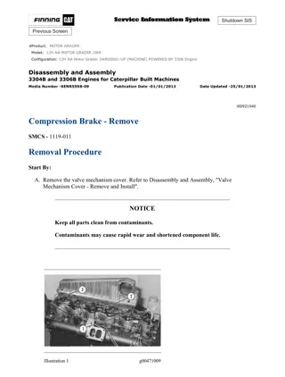
120K Motor Grader JAP00001-UP (MACHINE) POWERED BY C7 Engine(SEBP49... 1/35 Shutdown SIS Previous Screen Product: MOTOR GRADER Model: 120K MOTOR GRADER JAP Configuration: 120K Motor Grader JAP00001-UP (MACHINE) POWERED BY C7 Engine Disassembly and Assembly 120K and 120K Series 2 Motor Graders Power Train Media Number -KENR8438-04 Publication Date -01/08/2018 Date Updated -09/08/2018 i05303122 Transmission - Assemble SMCS - 3002-016; 3030-016; 3159-016 Assembly Procedure Table 1 Required Tools Tool Part Number Part Description Qty A 5P-9736 Link Bracket 1 B 154-6181 Forcing Screw 2 C 6V-5221 Bolt 1 D 4C-8156 Lifting Fixture 1 E 6V-3918 Bolt 1 F 4C-8157 Lifting Fixture 2 G 1U-6405 Three Jaw Puller 1 H 1U-6341 Threaded Rod 1 J 5P-7970 Nut 1 K 9U-7479 Compressing Tube 1 L 5B-0637 High Idle Nut 1 5F-7353 Washer 1 1B-4207 Full Nut 2 5F-7369 Puller Leg 2 3H-0465 Push-Puller Plate 2 https://127.0.0.1/sisweb/sisweb/techdoc/techdoc_print_page.jsp?returnurl=/sis... 2020/3/11
120K Motor Grader JAP00001-UP (MACHINE) POWERED BY C7 Engine(SEBP49... 2/35 5F-7366 Forcing Screw 1 5P-4808 Cap 2 1U-9895 Crossblock 1 9S-9151 Block 2 M 1B-4206 Nut 4 8B-7552 Forcing Bolt 2 N 1U-6343 Threaded Rod 1 P 6V-8149 Nut 1 Q 2P-8312 Retaining Ring Pliers 1 1P-2326 Forcing Screw 1 1P-2325 Head 1 R 3H-0462 Bolt 4 8H-0709 Strap 4 5F-7373 Jaw 3 S 3E-3882 Eyebolt 1 T 6V-5765 Sealant 1 Note: Remove old anaerobic sealant from the bottom of the blind tapped holes in housing (11) before assembling. Illustration 1 g00623302 1. Lower the temperature of bearing outer races (130) . Install bearing outer races (130) to the original locations in both transmission case assembly (3) (not shown) and the transmission cover assembly (11) until bearing outer races (130) are seated. https://127.0.0.1/sisweb/sisweb/techdoc/techdoc_print_page.jsp?returnurl=/sis... 2020/3/11
https://www.ebooklibonline.com Hello dear friend! Thank you very much for reading. Enter the link into your browser. The full manual is available for immediate download. https://www.ebooklibonline.com
120K Motor Grader JAP00001-UP (MACHINE) POWERED BY C7 Engine(SEBP49... 3/35 Illustration 2 g00623301 2. Install bearing retainer (128) on gear assembly (126) . 3. Heat ball bearing (127) to a maximum of 135 C (275 F). Install ball bearing (127) to the original location on gear assembly (126) . 4. Use Tooling (Q) in order to install snap ring (129) to the original location on gear assembly (126) . Illustration 3 g00623300 5. Install gear assembly (126) to the original location in the transmission cover assembly (11) . 6. Install two bolts (not shown) on the gear assembly (126) . 7. Install four bolts (125) in the gear assembly (126) . Tighten bolts (125) to a torque of 28 7 N m (21 5 lb ft). https://127.0.0.1/sisweb/sisweb/techdoc/techdoc_print_page.jsp?returnurl=/sis... 2020/3/11
120K Motor Grader JAP00001-UP (MACHINE) POWERED BY C7 Engine(SEBP49... 4/35 Illustration 4 g00623299 8. Install the cup plug (not shown) in input shaft assembly (65) . 9. Install gear (124) on Input shaft assembly (65) . 10. Heat inner bearing (123) to a maximum of 135 C (275 F). Install inner bearing (123) on Input shaft assembly (65) until inner bearing (123) is seated. Gear (124) should be tight on input shaft assembly (65) . 11. Install two seal rings (122) to the original locations on Input shaft assembly (65) . Illustration 5 g01024466 12. Install Tooling (S) to Input shaft assembly (65) . Use a hoist in order to position Input shaft assembly (65) to the original location in the transmission case assembly (11) . Install Input shaft assembly (65) in the transmission case assembly (11) . Remove Tooling (S) from Input shaft assembly (65) . https://127.0.0.1/sisweb/sisweb/techdoc/techdoc_print_page.jsp?returnurl=/sis... 2020/3/11
120K Motor Grader JAP00001-UP (MACHINE) POWERED BY C7 Engine(SEBP49... 5/35 Illustration 6 g00623297 Illustration 7 g00623294 13. Install seal rings (121) on piston (120) . Install both seal rings (121) with the sealing lips facing toward the small diameter of piston (120) . 14. Place Forward shaft assembly (95) in the modified work bench or on blocks. Apply a light coat of clean hydraulic oil on seal rings (121) . Install piston (120) at the original location on Forward shaft assembly (95) . Slightly rotate piston (120) while the seal is being installed. Ensure that the seal rings (121) are installed properly. 15. Install valve assembly (119) to the original location on Forward shaft assembly (95) . https://127.0.0.1/sisweb/sisweb/techdoc/techdoc_print_page.jsp?returnurl=/sis... 2020/3/11
120K Motor Grader JAP00001-UP (MACHINE) POWERED BY C7 Engine(SEBP49... 6/35 Illustration 8 g00623292 16. Install six clutch plates (117) and seven friction discs (118) in the original order on hub assembly (115) . The splines on hub assembly (115) must align with the splines on the friction discs (118) . 17. Install spring (116) in the original location on Forward shaft assembly (95) . 18. As one unit, install hub assembly (115) , six clutch plates (117) and seven friction discs (118) to the original location on Forward shaft assembly (95) . Illustration 9 g00623291 19. Use a second person in order to manually compress clutch assembly (113) on spring (116) . 20. Install two half rings (114) in the Forward shaft assembly (95) . https://127.0.0.1/sisweb/sisweb/techdoc/techdoc_print_page.jsp?returnurl=/sis... 2020/3/11
120K Motor Grader JAP00001-UP (MACHINE) POWERED BY C7 Engine(SEBP49... 7/35 Illustration 10 g00623665 21. Install the washer and thrust disc (112) to the original locations on Forward shaft assembly (95) . Illustration 11 g00623672 22. Install gear assembly (110) on Forward shaft assembly (95) and over clutch assembly (113) . Align the spline teeth on the outer diameter of the clutch plates (117) with the splines on the inside of gear assembly (110) . Ensure that gear assembly (110) is completely down over the clutch assembly (113) . https://127.0.0.1/sisweb/sisweb/techdoc/techdoc_print_page.jsp?returnurl=/sis... 2020/3/11
120K Motor Grader JAP00001-UP (MACHINE) POWERED BY C7 Engine(SEBP49... 8/35 Illustration 12 g00623673 23. Install roller bearing (111) to the original location on Forward shaft assembly (95) . Illustration 13 g00623736 24. Install two thrust discs (131) and thrust race (132) on Forward shaft assembly (95) . The thrust discs (131) should not spin the thrust race (132) . Illustration 14 g00623738 25. Heat inner bearing (109) to a maximum of 132 C (270 F). Install inner bearing (109) on Forward shaft assembly (95) until inner bearing (109) contacts the bearing race. 26. Position Forward shaft assembly (95) , as shown. The weight of Forward shaft assembly (95) is approximately 43 kg (95 lb). Place Forward shaft assembly (95) in the modified work bench or blocks. https://127.0.0.1/sisweb/sisweb/techdoc/techdoc_print_page.jsp?returnurl=/sis... 2020/3/11
120K Motor Grader JAP00001-UP (MACHINE) POWERED BY C7 Engine(SEBP49... 9/35 Illustration 15 g00623287 27. Install lip seals (108) in piston (107) . Install lip seals (108) with the sealing lip toward the small diameter of piston (107) . 28. Apply a light coat of clean hydraulic oil on lip seals (108) . Illustration 16 g00623285 29. Install piston (107) to the original location on Forward shaft assembly (95) . Rotate the piston slightly while the seal is being installed. Ensure that the lip seals are installed properly. 30. Install valve assembly (106) to the original location on Forward shaft assembly (95) . https://127.0.0.1/sisweb/sisweb/techdoc/techdoc_print_page.jsp?returnurl=/sis... 2020/3/11
120K Motor Grader JAP00001-UP (MACHINE) POWERED BY C7 Engine(SEBP... 10/35 Illustration 17 g00623284 Note: Friction discs 1 and 7 are different from the remaining discs. Assemble friction discs (1) and (7) with the grooved pattern toward the center of the clutch pack. 31. Install six clutch plates (105) and seven friction discs (103) in the original order on hub assembly (102) . The splines on hub assembly (102) must align with the splines on the friction plates. 32. Install spring (104) to the original location on Forward shaft assembly (95) . 33. As one unit, install hub assembly (102) , six clutch plates (105) , and seven friction discs (103) to the original location on Forward shaft assembly (95) . Illustration 18 g00623281 34. Use two people to manually compress hub assembly (100) on spring (94) . Install two half rings (101) in Forward shaft assembly (95) . https://127.0.0.1/sisweb/sisweb/techdoc/techdoc_print_page.jsp?returnurl=/sis... 2020/3/11
120K Motor Grader JAP00001-UP (MACHINE) POWERED BY C7 Engine(SEBP... 11/35 Illustration 19 g00623746 35. Install thrust disc and washer (99) on Forward shaft assembly (95) . The thrust disc should not spin the washer. Illustration 20 g00623747 Illustration 21 g00634016 36. Install gear assembly (97) on Forward shaft assembly (95) and over clutch assembly (100) . Align the spline teeth on the outer diameter of the clutch plates with the splines on the https://127.0.0.1/sisweb/sisweb/techdoc/techdoc_print_page.jsp?returnurl=/sis... 2020/3/11
120K Motor Grader JAP00001-UP (MACHINE) POWERED BY C7 Engine(SEBP... 12/35 inside of gear assembly (97) . Ensure that the gear assembly (97) is completely down over hub assembly (102) . 37. Install roller bearing (98) to the original location on Forward shaft assembly (95) . 38. Install the two thrust discs on Forward shaft assembly (95) . Illustration 22 g00623756 39. Heat bearing (96) to a maximum of 132 C (270 F). Install bearing (96) on Forward shaft assembly (95) until bearing (96) contacts the bearing race. Illustration 23 g01024454 40. Install Tooling (S) in Forward shaft assembly (95) . Install Forward shaft assembly (95) to the original location in the transmission cover assembly (11) . The weight of Forward shaft assembly (95) is approximately 63.6 kg (140 lb). Remove Tooling (S) . https://127.0.0.1/sisweb/sisweb/techdoc/techdoc_print_page.jsp?returnurl=/sis... 2020/3/11
120K Motor Grader JAP00001-UP (MACHINE) POWERED BY C7 Engine(SEBP... 13/35 Illustration 24 g00623276 41. Install the cup plug (not shown) from Reverse/Second shaft assembly (68) . 42. Install seals (93) and (94) with the sealing lip toward the small diameter of piston (92) . Illustration 25 g00623270 43. Place Reverse/Second shaft assembly (68) in the modified work bench, or on blocks. Apply a light coat of clean hydraulic oil on the lip seals. Install piston (92) to the original location on Reverse/Second shaft assembly (68) . Rotate the piston slightly while the seal is being installed. Ensure that the lip seals are installed properly. 44. Install valve assembly (91) to the original location on Reverse/Second shaft assembly (68) . https://127.0.0.1/sisweb/sisweb/techdoc/techdoc_print_page.jsp?returnurl=/sis... 2020/3/11
120K Motor Grader JAP00001-UP (MACHINE) POWERED BY C7 Engine(SEBP... 14/35 Illustration 26 g00623269 45. Install six clutch plates (88) and seven friction disc (90) in the original order on hub assembly (87) . The splines on the hub assembly (87) must align with the splines on the friction discs (90) . 46. Install spring (89) in the original location on Reverse/Second shaft assembly (68) . 47. As one unit, install hub assembly (87) , six clutch plates (88) , and seven friction discs (90) to the original location on Reverse/Second shaft assembly (68) . Illustration 27 g00623265 48. Use two people to manually compress clutch plate (85) on spring (89) . Install two half rings (86) in Reverse/Second shaft assembly. https://127.0.0.1/sisweb/sisweb/techdoc/techdoc_print_page.jsp?returnurl=/sis... 2020/3/11
120K Motor Grader JAP00001-UP (MACHINE) POWERED BY C7 Engine(SEBP... 15/35 Illustration 28 g00623760 49. Install the washer and thrust disc (84) to the original locations on Reverse/Second shaft assembly (68) . The thrust disc should not spin the washer. 50. Install gear assembly (82) on Reverse/Second shaft assembly (68) . Align the spline teeth on the outer diameter of the clutch plates with the splines on the inside of gear assembly (82) . Ensure that the gear assembly (82) is completely down over the clutch assembly (85) . Illustration 29 g00634018 51. Install roller bearing (83) to the original location on Reverse/Second shaft assembly (68) . https://127.0.0.1/sisweb/sisweb/techdoc/techdoc_print_page.jsp?returnurl=/sis... 2020/3/11
120K Motor Grader JAP00001-UP (MACHINE) POWERED BY C7 Engine(SEBP... 16/35 Illustration 30 g00634020 52. Install two thrust discs and one thrust race (133) . Illustration 31 g00634021 53. Heat inner bearing (81) to a maximum of 132 C (270 F). Install inner bearing (81) on Reverse/Second shaft assembly (68) until inner bearing (81) contacts the bearing race. The thrust disc should not spin. Illustration 32 g00623260 https://127.0.0.1/sisweb/sisweb/techdoc/techdoc_print_page.jsp?returnurl=/sis... 2020/3/11
120K Motor Grader JAP00001-UP (MACHINE) POWERED BY C7 Engine(SEBP... 17/35 Illustration 33 g00623261 54. Position Reverse/Second shaft assembly (68) , as shown. The weight of Reverse/Second shaft assembly (68) is approximately 41 kg (90 lb). Place Reverse/Second shaft assembly (68) in the modified work bench or on blocks. 55. Apply a light coat of clean hydraulic oil on the lip seals. Install lip seals (79) and (80) in piston (78) . Install lip seals (79) and (80) with the sealing lip toward the small diameter of the piston (78) . Rotate the piston slightly while the seal is being installed. 56. Install piston (78) to the original location on Reverse/Second shaft assembly (68) . Ensure that the lip seals are installed properly. 57. Install wave spring (77) on Reverse/Second shaft assembly (68) . Illustration 34 g00623259 58. Install clutch assembly (74) on Reverse/Second shaft assembly (68) . Position the three clutch plates, the four friction disc, and the hub assembly in the original locations on Reverse/Second shaft assembly (68) . 59. Install Tooling (K) and Tooling (H) on Reverse/Second shaft assembly (68) . Tighten Tooling (J) on Tooling (H) in order to compress clutch assembly (74) . Install two half rings (75) and two lock rings (76) in Reverse/Second shaft assembly (68) . https://127.0.0.1/sisweb/sisweb/techdoc/techdoc_print_page.jsp?returnurl=/sis... 2020/3/11
120K Motor Grader JAP00001-UP (MACHINE) POWERED BY C7 Engine(SEBP... 18/35 60. Carefully loosen Tooling (J) on Tooling (H) in order to relieve pressure from clutch assembly (74) . Remove Tooling (H) and Tooling (K) from clutch assembly (74) . Illustration 35 g00623258 61. Install the thrust disc and the washer on Reverse/Second shaft assembly (68) . 62. Install the sleeve bearing (not shown) on Reverse/Second shaft assembly (68) . 63. Install gear assembly (73) on Reverse/Second shaft assembly (68) . Align the spline teeth on the outer diameter of the clutch plates with the splines on the inside of gear assembly (73) . Ensure that gear assembly (73) is down over the clutch assembly completely. 64. Install the thrust disc (not shown) and spacer (72) to the original locations on Reverse/Second shaft assembly (68) . Illustration 36 g00623761 65. Install gear (71) on Reverse/Second shaft assembly (68) . 66. Install spacer (70) on Reverse/Second shaft assembly (68) . 67. Heat bearing (69) to a maximum of 132 C (270 F). Install bearing (69) on Reverse/Second shaft assembly (68) until bearing (69) contacts spacer (70) . Spacer (70) should not spin. https://127.0.0.1/sisweb/sisweb/techdoc/techdoc_print_page.jsp?returnurl=/sis... 2020/3/11
120K Motor Grader JAP00001-UP (MACHINE) POWERED BY C7 Engine(SEBP... 19/35 Illustration 37 g01024451 68. Install Tooling (S) in Reverse/Second shaft assembly (68) . Place Reverse/Second shaft assembly (68) to the original location in the transmission case assembly (11) . The weight of Reverse/Second shaft assembly (68) is approximately 64 kg (141 lb). Remove Tooling (S) . Illustration 38 g00623801 69. Install gear (67) to the original location on Input shaft assembly (65) . 70. Heat inner bearing (66) to a maximum of 132 C (270 F). Install inner bearing (66) on Input shaft assembly (65) until inner bearing (66) contacts gear (67) . Gear (67) should be tight on input shaft assembly (65) . https://127.0.0.1/sisweb/sisweb/techdoc/techdoc_print_page.jsp?returnurl=/sis... 2020/3/11
120K Motor Grader JAP00001-UP (MACHINE) POWERED BY C7 Engine(SEBP... 20/35 Illustration 39 g00623250 71. Install seal extension ring (63) and seal ring (64) on piston (62) . Install seal (63) and seal (64) with the sealing lips toward the small diameter of the piston (62) . Apply a light coat of clean hydraulic oil on the lip seals of piston (62) . Illustration 40 g00623249 72. Place First/Third shaft assembly (14) in the modified work bench, or on blocks. Install piston (62) to the original location on First/Third shaft assembly (14) . Rotate the piston (62) slightly while the seal is being installed. Ensure that the lip seals are installed properly. 73. Install wave spring (61) to the original location on First/Third shaft assembly (14) . https://127.0.0.1/sisweb/sisweb/techdoc/techdoc_print_page.jsp?returnurl=/sis... 2020/3/11
Suggest: If the above button click is invalid. Please download this document first, and then click the above link to download the complete manual. Thank you so much for reading
120K Motor Grader JAP00001-UP (MACHINE) POWERED BY C7 Engine(SEBP... 21/35 Illustration 41 g00623248 74. As you install clutch assembly (58) to First/Third shaft assembly (14) , position the three clutch plates, four friction disc and the hub assembly to the original locations on First/Third shaft assembly (14) . 75. Install Tooling (K) and Tooling (H) on First/Third shaft assembly (14) . Tighten Tooling (J) on Tooling (H) in order to compress clutch assembly (58) . Install two half rings (59) and two lock rings (60) to First/Third shaft assembly (14) . 76. Carefully loosen the nut on Tooling (J) in order to relieve pressure from clutch assembly (58) . Remove Tooling (K) and Tooling (H) . Illustration 42 g00634025 77. Install the washer, the thrust disc, and the bearing sleeve to the original locations on First/Third shaft assembly (14) . 78. Install gear assembly (57) in the original location on First/Third shaft assembly (14) and over clutch assembly (58) . Align the spline teeth on the outer diameter of the clutch plates with the splines on the inside of gear assembly (57) . Ensure that the gear assembly (57) is completely down over clutch assembly (58) . 79. Install the thrust disc that was under gear (56) to the original location on First/Third shaft assembly (14) . https://127.0.0.1/sisweb/sisweb/techdoc/techdoc_print_page.jsp?returnurl=/sis... 2020/3/11
https://www.ebooklibonline.com Hello dear friend! Thank you very much for reading. Enter the link into your browser. The full manual is available for immediate download. https://www.ebooklibonline.com

 POWERED BY C7")
 POWERED BY C7")

 POWERED BY C7")
 POWERED BY C7")
 POWERED BY C7")
 POWERED BY C7")
 POWERED BY C7")
 POWERED BY C7")
 POWERED BY C7")
 POWERED BY C7")
 POWERED BY C7")
 POWERED BY C7")
 POWERED BY C7")
 POWERED BY C7")
 POWERED BY C7")
 POWERED BY C7")
 POWERED BY C7")
 POWERED BY C7")
 POWERED BY C7")
 POWERED BY C7")

 POWERED BY C7")