Antennas


Antennas

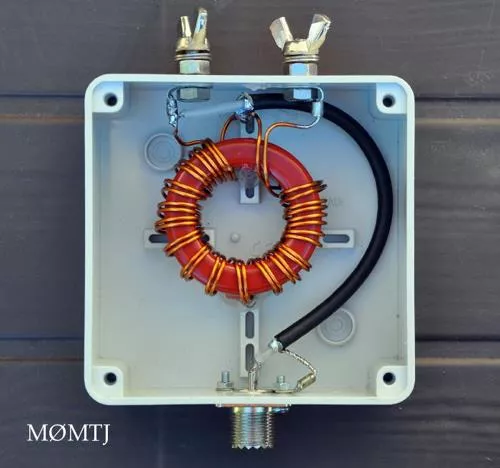
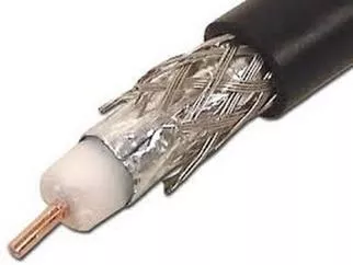
Baluns
•
A
balun
is a device to match a
balanced
antenna
to
unbalanced
transmission line
such as coax
•
Used e.g. to connect a dipole
antenna to a 50 ohm coaxial
cable, where it would be
installed
between the coaxial
cable and the antenna

SWR (Standing Wave Ratio)
•
If the characteristic impedance of the transmission line does not
match the antenna input impedance then standing waves are
produced in the transmission line
•
SWR = the ratio of maximum to minimum voltages on a
transmission line
SWR
•
If your antenna transmission line gets hot when you are
transmitting the SWR may be too high, or the transmission
line loss may be high
•
The result of the presence of standing waves on a
transmission line is: reduced transfer of RF energy to the
antenna
•
An SWR meter measures the degree of match between
transmission line and antenna by
comparing forward and
reflected voltage
•
When a resonant antenna with feed point impedance of 200
ohms is connected to a transmission line with impedance of 50
ohms the standing wave ratio of this system will be 200:50 ->
4:1
Antennas
Antennas are used to convert radio
frequency alternating electric current
into an electromagnetic field and vice
versa.
•
Resonant
•
Impedance matched
Resonance
•
Length be right for frequency
–
1/4, 1/2, 5/8 and full wave length, depending on
type
•
Below 30MHz/10m, shortening factor of 0.95
•
Resonance means
inductive reactance and
capacitive reactance are equal
•
There will be questions involving frequency
and/or antenna length on the exam
I will put a few of them up during the break
Frequency vs Wavelength calculation
•
Wavelength vs frequency calculation
–
λ = c / f
•
where c is the speed of light
–
λ(m) =
300,000,000m/s
/ f(Hz = 1/s)
–
λ(m) = 300/f(MHz)
•
Shorter – frequency increases
•
Longer – frequency decreases (eg adding to
length with series inductance)
Antenna Impedance - Resonant
•
Antennas have an inherent impedance at resonance
•
A source delivers maximum power to the load when the
impedance of an electrical load is equal to the internal
impedance of the power source
•
Antenna impedance needs to be matched with the feed line;
if they don’t use an
impedance-matching device
•
A 75 ohm transmission line could be matched to the 300 ohm
feed point of an antenna by using a 4 to 1 impedance
transformer balun
•
But… resonance and impedance are frequency
dependent
Antenna Impedance – not resonant
•
While resonant, antennas present only a resistive load
•
Resonant at a specific frequency
•
When not resonant, there is also a reactive load, so
impedance of antenna changes
•
if an antenna’s impedance changes, it’s no longer matched to
the feed line
•
Mismatched -> SWR will increase
•
Antenna Bandwidth – frequency range over which the
antenna may be expected to perform well
•
Frequency span where SWR is < 2:1
•
So can you use an antenna outside of its bandwidth?
Antenna Tuner
•
might allow use of an antenna on a band it was
not designed for
•
matches transceiver to a mismatched antenna system
•
Used with most antennas when operating
below 14 MHz/20m
•
Does it make sense how the last 5 slides
fit together?
Diversions
•
Search “Design of armor for protection against blast and
impact”
–
A novel design concept called
impact
or
blast tuning
is
introduced in which a multi-layered armor is used to tune
the stress waves resulting from an impact or blast to
specific frequencies that match the damping frequencies
of visco-elastic layers
•
Rectenna -
specialized radio antenna with an RF diode which
is used to convert radio waves into direct current electricity
•
Nantenna
- convert light to electric power
Polarization
•
Polarization of the radio wave is determined by the orientation
of the electric field
•
Horizontal – parallel to earth’s surface
•
Vertical – perpendicular to earth’s surface
(at right angle to)
•
Antennas are polarized parallel to their length
•
For VHF and higher, polarization at sending and receiving end
need to be same; HF doesn’t matter because
the ionosphere
can change the polarization of the signal from moment to
moment
There are a bunch of questions about antenna polarization on the exam
Isotropic radiator
A hypothetical, lossless antenna having equal
radiation intensity in all directions.
Antenna radiation pattern is a sphere
In discussing gain, the “i” dBi is for isotropic
If not a sphere, the antenna has directivity
Antenna Gain and Directivity
•
Gain:
The numerical ratio relating the radiated signal
strength of an antenna to that of another antenna
•
Directivity: narrow or sharp pattern = increased directivity
•
front-to-back ratio is the ratio of the maximum forward
power in the major lobe to the maximum backward power
Antenna Types
Considerations…
•
Available space
•
Regulations
•
Directivity and gain
Different antenna types provide advantages and
disadvantages
Random Wire
•
Random Wire antenna
– any length, any direction, easy but
not very effective.
•
when sending
you may experience RF
feedback in your station
Dipole – description
has an impedance of
~73Ω
– good for coax (50-75Ω)
Dipole – antenna pattern
Low angle radiation pattern
of an ideal half-wavelength
dipole in free space is a
figure-eight perpendicular
to the antenna
If antenna ends were north-
south then a dipole would
radiate perpendicular to
that, ie mostly to the
east
and west
.
dipole
gain over isotropic
radiator is 2.1dB
Folded Dipole
•
has impedance of
~300Ω
– works well with
twin lead feedline (150-600Ω)
•
has
greater bandwidth than simple dipole
Vertical Antenna
Will receive signals equally well from all around it
Vertical dipole where the bottom half gets special
consideration or might be just the ground (image
or virtual antenna)
Vertical Antenna - ground plane
•
Changing the slope from horizontal to downward-
sloping
increases the feed point impedance
•
Advantage of downward sloping radials on a ground
plane antenna is that it
brings the feed point
impedance closer to 50 ohm
•
50 ohm coaxial cable
is best match
transmission line for ground plane
antenna
•
Ground plane can be ground, or
wires at least 1/4 wavelength
long
•
antenna with horizontal ground
plane has impedance of
36
ohm
Vertical Antenna - 5/8 wave length
Many VHF antennas are 5/8 wavelength because the
angle
of radiation is low
Loading Coils
HF mobile vertical antennas often
use a loading coil to tune out
capacitive reactance
Loading coil adds inductive reactance
to cancel out capacitive reactance of
an electrically short antenna
Bit too long – it’s inductive
Bit too short – it’s capacitive
Traps
•
A trap is a
coil in parallel with a capacitor
, connected in series
with the antenna
•
Traps let through to the longer part of the antenna only the
lower frequencies that require that longer antenna length
•
Traps allow the use of an antenna for multi-band operation
•
Disadvantage is that
an antenna equipped with traps may
radiate harmonics more readily
Parasitic Elements
•
Modifies radiation pattern by increasing gain
•
Absorbs radiation and re-radiates in different
phase
Yagi
•
Three elements
, only one element is driven, and it is usually a
half wave dipole (so calculation for it applies)
Yagi
•
Gain 5dBi for just driven and reflector, 7dB with one director,
and +1dB
gain for additional directors
•
Front-to-back ratio up to 25dB
•
“Best compromise” spacing between elements is
0.2
wavelengths
•
Some advantages of a Yagi with wide element spacing are high
gain, less critical tuning and wider bandwidth
•
A good way to get maximum performance out of a Yagi
antenna is to optimize the lengths and spacing of the elements
•
Yagi antennas are good for busy bands like the 20m band
because they are very directive, which
helps reduce interference
from other stations off to the side or behind
•
Adding an identical Yagi antenna in same direction
(stacking)
increases gain by 3dB
Cubic Quad
•
T
w
o
o
r
m
o
r
e
p
a
r
a
l
l
e
l
f
o
u
r
-
s
i
d
e
d
w
i
r
e
l
o
o
p
s
,
e
a
c
h
a
p
p
r
o
x
i
m
a
t
e
l
y
o
n
e
-
e
l
e
c
t
r
i
c
a
l
w
a
v
e
l
e
n
g
t
h
l
o
n
g
•
C
o
m
p
a
r
e
d
t
o
a
d
i
p
o
l
e
t
h
e
c
u
b
i
c
a
l
q
u
a
d
h
a
s
m
o
r
e
d
i
r
e
c
t
i
v
i
t
y
i
n
b
o
t
h
h
o
r
i
z
o
n
t
a
l
a
n
d
v
e
r
t
i
c
a
l
p
l
a
n
e
.
•
T
w
o
-
e
l
e
m
e
n
t
d
e
l
t
a
l
o
o
p
s
a
n
d
q
u
a
d
a
n
t
e
n
n
a
s
c
o
m
p
a
r
e
f
a
v
o
u
r
a
b
l
y
w
i
t
h
a
t
h
r
e
e
-
e
l
e
m
e
n
t
y
a
g
i
.
Delta Loop
•
A
n
a
n
t
e
n
n
a
w
h
o
s
e
e
l
e
m
e
n
t
s
a
r
e
e
a
c
h
a
t
h
r
e
e
s
i
d
e
d
l
o
o
p
w
h
o
s
e
t
o
t
a
l
l
e
n
g
t
h
i
s
a
p
p
r
o
x
i
m
a
t
e
l
y
o
n
e
e
l
e
c
t
r
i
c
a
l
w
a
v
e
l
e
n
g
t
h
•
T
w
o
-
e
l
e
m
e
n
t
d
e
l
t
a
l
o
o
p
s
a
n
d
q
u
a
d
a
n
t
e
n
n
a
s
c
o
m
p
a
r
e
f
a
v
o
u
r
a
b
l
y
w
i
t
h
a
t
h
r
e
e
-
e
l
e
m
e
n
t
y
a
g
i
.
Special Case: Dummy
Load
•
Dummy load is essentially an antenna that radiates heat
instead of RF
•
temporarily connected in the tuning process or for
adjustments to the transmitter
•
Use a dummy load instead of the antenna during tuning to
cut
down on interference
•
Can be built out of resistors that can dissipate the power you
will use with it
(calculation on exam about this)
Antenna Safety
•
Bob Jacobs will tell you details next weekend
•
For now:
–
If you climb stuff think fall protection
–
Make sure no one can touch your antenna when
sending
For the break
•
How long?
•
If you are bored, consider doing these:
•
If you want something during the break,
•
What is the wavelength corresponding to a frequency of
2MHz?
•
If you made a quarter-wavelength vertical antenna for
21.125 MHz, how long would it be?
•
If you made a half-wavelength vertical antenna for 223 MHz,
how long would it be?
For the break (answers)
•
What is the wavelength corresponding to a frequency
of 2MHz?
•
150m
•
If you made a quarter-wavelength vertical antenna
for 21.125 MHz, how long would it be?
•
3.36m
•
If you made a half-wavelength vertical antenna for
223 MHz, how long would it be?
•
64 cm
Schedule
Ask if they remember
- baluns
- SWR
What is an antenna, and a good antenna
In the world of radio frequency communication, antennas play a vital role in converting electric current to electromagnetic fields. Matching impedance with devices like baluns ensures efficient signal transmission. Standing Wave Ratio (SWR) becomes crucial for assessing the balance between transmission line impedance and antenna input impedance. Resonance and frequency calculations further optimize antenna performance. Explore the essentials of antennas, SWR, resonance, and frequency-wavelength dynamics for a deeper understanding.

Download Presentation

Please find below an Image/Link to download the presentation.
The content on the website is provided AS IS for your information and personal use only. It may not be sold, licensed, or shared on other websites without obtaining consent from the author.If you encounter any issues during the download, it is possible that the publisher has removed the file from their server.
You are allowed to download the files provided on this website for personal or commercial use, subject to the condition that they are used lawfully. All files are the property of their respective owners.
The content on the website is provided AS IS for your information and personal use only. It may not be sold, licensed, or shared on other websites without obtaining consent from the author.
E N D
Presentation Transcript
Baluns A balun is a device to match a balanced antenna to unbalanced transmission line such as coax Used e.g. to connect a dipole antenna to a 50 ohm coaxial cable, where it would be installed between the coaxial cable and the antenna
SWR (Standing Wave Ratio) If the characteristic impedance of the transmission line does not match the antenna input impedance then standing waves are produced in the transmission line SWR = the ratio of maximum to minimum voltages on a transmission line
SWR If your antenna transmission line gets hot when you are transmitting the SWR may be too high, or the transmission line loss may be high The result of the presence of standing waves on a transmission line is: reduced transfer of RF energy to the antenna An SWR meter measures the degree of match between transmission line and antenna by comparing forward and reflected voltage When a resonant antenna with feed point impedance of 200 ohms is connected to a transmission line with impedance of 50 ohms the standing wave ratio of this system will be 200:50 -> 4:1
Antennas Antennas are used to convert radio frequency alternating electric current into an electromagnetic field and vice versa. Resonant Impedance matched
Resonance Length be right for frequency 1/4, 1/2, 5/8 and full wave length, depending on type Below 30MHz/10m, shortening factor of 0.95 Resonance means inductive reactance and capacitive reactance are equal There will be questions involving frequency and/or antenna length on the exam I will put a few of them up during the break
Frequency vs Wavelength calculation Wavelength vs frequency calculation = c / f where c is the speed of light (m) = 300,000,000m/s / f(Hz = 1/s) (m) = 300/f(MHz) Shorter frequency increases Longer frequency decreases (eg adding to length with series inductance)
Antenna Impedance - Resonant Antennas have an inherent impedance at resonance A source delivers maximum power to the load when the impedance of an electrical load is equal to the internal impedance of the power source Antenna impedance needs to be matched with the feed line; if they don t use an impedance-matching device A 75 ohm transmission line could be matched to the 300 ohm feed point of an antenna by using a 4 to 1 impedance transformer balun But resonance and impedance are frequency dependent
Antenna Impedance not resonant While resonant, antennas present only a resistive load Resonant at a specific frequency When not resonant, there is also a reactive load, so impedance of antenna changes if an antenna s impedance changes, it s no longer matched to the feed line Mismatched -> SWR will increase Antenna Bandwidth frequency range over which the antenna may be expected to perform well Frequency span where SWR is < 2:1 So can you use an antenna outside of its bandwidth?
Antenna Tuner might allow use of an antenna on a band it was not designed for matches transceiver to a mismatched antenna system Used with most antennas when operating below 14 MHz/20m Does it make sense how the last 5 slides fit together?
Diversions Search Design of armor for protection against blast and impact A novel design concept called impact or blast tuning is introduced in which a multi-layered armor is used to tune the stress waves resulting from an impact or blast to specific frequencies that match the damping frequencies of visco-elastic layers Rectenna - specialized radio antenna with an RF diode which is used to convert radio waves into direct current electricity Nantenna - convert light to electric power
Polarization Polarization of the radio wave is determined by the orientation of the electric field Horizontal parallel to earth s surface Vertical perpendicular to earth s surface (at right angle to) Antennas are polarized parallel to their length For VHF and higher, polarization at sending and receiving end need to be same; HF doesn t matter because the ionosphere can change the polarization of the signal from moment to moment There are a bunch of questions about antenna polarization on the exam
Isotropic radiator A hypothetical, lossless antenna having equal radiation intensity in all directions. Antenna radiation pattern is a sphere In discussing gain, the i dBi is for isotropic If not a sphere, the antenna has directivity
Antenna Gain and Directivity Gain: The numerical ratio relating the radiated signal strength of an antenna to that of another antenna Directivity: narrow or sharp pattern = increased directivity front-to-back ratio is the ratio of the maximum forward power in the major lobe to the maximum backward power
Antenna Types Considerations Available space Regulations Directivity and gain Different antenna types provide advantages and disadvantages
Random Wire Random Wire antenna any length, any direction, easy but not very effective. when sending you may experience RF feedback in your station
Dipole description has an impedance of ~73 good for coax (50-75 )
Dipole antenna pattern dipole gain over isotropic radiator is 2.1dB Low angle radiation pattern of an ideal half-wavelength dipole in free space is a figure-eight perpendicular to the antenna If antenna ends were north- south then a dipole would radiate perpendicular to that, ie mostly to the east and west.
Folded Dipole has impedance of ~300 works well with twin lead feedline (150-600 ) has greater bandwidth than simple dipole
Vertical Antenna Vertical dipole where the bottom half gets special consideration or might be just the ground (image or virtual antenna) Will receive signals equally well from all around it
Vertical Antenna - ground plane Ground plane can be ground, or wires at least 1/4 wavelength long antenna with horizontal ground plane has impedance of 36 ohm 50 ohm coaxial cable is best match transmission line for ground plane antenna Advantage of downward sloping radials on a ground plane antenna is that it brings the feed point impedance closer to 50 ohm Changing the slope from horizontal to downward- sloping increases the feed point impedance
Vertical Antenna - 5/8 wave length Many VHF antennas are 5/8 wavelength because the angle of radiation is low
Loading Coils Loading coil adds inductive reactance to cancel out capacitive reactance of an electrically short antenna Bit too long it s inductive Bit too short it s capacitive HF mobile vertical antennas often use a loading coil to tune out capacitive reactance
Traps A trap is a coil in parallel with a capacitor, connected in series with the antenna Traps let through to the longer part of the antenna only the lower frequencies that require that longer antenna length Traps allow the use of an antenna for multi-band operation Disadvantage is that an antenna equipped with traps may radiate harmonics more readily
Parasitic Elements Modifies radiation pattern by increasing gain Absorbs radiation and re-radiates in different phase
Yagi Three elements, only one element is driven, and it is usually a half wave dipole (so calculation for it applies)
Yagi Gain 5dBi for just driven and reflector, 7dB with one director, and +1dB gain for additional directors Front-to-back ratio up to 25dB Best compromise spacing between elements is 0.2 wavelengths Some advantages of a Yagi with wide element spacing are high gain, less critical tuning and wider bandwidth A good way to get maximum performance out of a Yagi antenna is to optimize the lengths and spacing of the elements Yagi antennas are good for busy bands like the 20m band because they are very directive, which helps reduce interference from other stations off to the side or behind Adding an identical Yagi antenna in same direction (stacking) increases gain by 3dB
Cubic Quad Two or more parallel four-sided wire loops, each approximately one-electrical wavelength long Compared to a dipole the cubical quad has more directivity in both horizontal and vertical plane. Two-element delta loops and quad antennas compare favourably with a three-element yagi.
Delta Loop An antenna whose elements are each a three sided loop whose total length is approximately one electrical wavelength Two-element delta loops and quad antennas compare favourably with a three-element yagi.
Special Case: Dummy Load Dummy load is essentially an antenna that radiates heat instead of RF temporarily connected in the tuning process or for adjustments to the transmitter Use a dummy load instead of the antenna during tuning to cut down on interference Can be built out of resistors that can dissipate the power you will use with it (calculation on exam about this)
Antenna Safety Bob Jacobs will tell you details next weekend For now: If you climb stuff think fall protection Make sure no one can touch your antenna when sending
For the break How long? If you are bored, consider doing these: If you want something during the break, What is the wavelength corresponding to a frequency of 2MHz? If you made a quarter-wavelength vertical antenna for 21.125 MHz, how long would it be? If you made a half-wavelength vertical antenna for 223 MHz, how long would it be?
For the break (answers) What is the wavelength corresponding to a frequency of 2MHz? 150m If you made a quarter-wavelength vertical antenna for 21.125 MHz, how long would it be? 3.36m If you made a half-wavelength vertical antenna for 223 MHz, how long would it be? 64 cm
Schedule Date Topic Instructor Feb 20 - 9 AM Chapter 2: Basic Theory Rob Striemer (VE4SHS) Feb-20 Chapter 3: Ohm s Law & Power Rob Striemer Feb-20 Chapter 4: Inductors & Capacitors Rob Striemer Feb 20 - 1 PM Chap. 1: Introduction to Amateur Radio Dylan Fijal (VA4DFJ) Feb-20 Chapter 12: Q codes, phonetics, emerg comms, etc. Dylan Fijal Feb-20 Chapter 17: Regulations, Towers, etc. Dylan Fijal Feb 27 - 9 AM Chapter 5: Wavelength, Frequency and Bands Collin Stanners (VE4CST) Feb 27 - 9 AM Chapter 6: Propagation Collin Stanners Feb 27 - 9 AM Ch. 7: Transmission Lines Collin Stanners Feb 27 - 1 PM Ch. 10: Power Supplies Peter Toth (VE4TTH) Feb 27 - 1 PM Chapter 11: Setting up an Amateur Radio Station Peter Toth Feb 27 - 1 PM Chapter 12: Operating an Amateur Radio Station Peter Toth March 5 - 9 AM Chapter 8: Antennas Tina Tenbergen (VA4THN) Mar-05 Chapter 8: Antennas Tina Tenbergen Mar-05 Chapter 9: Diodes, Transistors and Tubes Tina Tenbergen March 5 - 1 PM Chapter 13: Modulation and Transmitters Jim Townsend (VE4CY) Mar-05 Chapter 14: Receivers Jim Townsend Mar-05 Practice Exam March 12 9 AM Chapter 15: Radio Frequency Interference Bob Jacobs (VE4RCJ) Mar-12 Chapter 16: Safety Bob Jacobs Mar-12 Review March 12 - 1 PM Review & Practice Exam Rob Striemer March 19 9 AM Industry Canada Final Exam 9:00 AM Adam Romanchuk March 19 11 AM 11:00 AM - workshop: How to get started, tips, etc.


")


")