Antennas: Basics and Classifications

ANTENNAS
ANTENNA – AN
 
INTRODUCTION:
An antenna 
may 
be a piece of conducting material in the form of a wire, rod or 
any
other shape with excitation. 
It  
converts radio frequency electrical current into an
electromagnetic waves 
of 
the same frequency. 
An 
antenna can also be called as a transducer
which converts electrical energy into electromagnetic radiant energy. Since it matches or
couples the transmitter/ receiver and free space, an antenna is also an impedance matching
device. The transmitter antenna radiates the electromagnetic waves and 
the 
receiver antenna
collects the electromagnetic waves. Apart from their different function transmitting and
receiving antennas 
behave
 
identically.
BASIC ANTENNA ACTION:
An antenna is a device and 
may 
be described 
as 
a metallic object, often a wire or a
collection of wires (linear conductors), used to convert high-frequency current into
electromagnetic waves, or vice versa. The length of the antenna varies from a fraction to
several wavelengths.
The
 
basic
 
principle
 
behind
 
the
 
working
 
of
 
an
antenna can be understood from the action of current
element. 
If 
the length of an antenna is much smaller than
the wavelength of 
the 
radio 
frequency 
wave in operation,
then it is called as a current element.. 
Any 
linear antenna
can be considered to 
be 
a chain of current
 
element.
Basically
 
a
 
current
 
element
 
is
 
an
 
electric
 
dipole.
Sine the current element has distributed capacitance,
inductance and resistance; 
It 
can be 
supposed 
to be a
series 
LCR 
circuit. The equivalent circuit of a current
element is shown in the figure
 
(1).
Consider  that  an  alternating  emf  is  feed  to 
 
the
current element. 
Consider 
that the cycle starts when the
capacitor is charged to maximum potential difference.
 
Let
the
 
upper
 
plate
 
is
 
positive
 
with
 
respect
 
to
 
the
 
lower
 
plate.
 
The
 
current
 
in
 
the
 
wire
 
is
 
zero.
 
At
this instant, the field in the 
vicinity 
of antenna 
may 
be regarded as 
purely 
electric. The electric
lines can be represented as in fig
 
(2a).
After the moment of 
maximum 
potential difference, 
the 
electrons start to flow &
constitute a current. The electric field begins to collapses as in fig. (2b). 
Due 
to electric inertia
the current continues to flow even after the potential difference across the capacitor is
 
reduced
Dr
 
RM
Downloaded 
from 
the website
 
ww.aadhi2ani.synthasite.com
Page
 
1
to zero. As a result the capacitor starts to charge in opposite direction. 
This 
will setup a 
new
electric field between the plates. 
If 
the initial electric field lags on 
the 
changes in 
the 
potential
which causes it, then this new electric field will start to build up before the first one has
disappeared. As a result, the first disturbance is repulsed outward in the form of closed loops
by 
the 
new 
electric field as shown in fig
 
(2c).
Any
 
changing
 
or
 
moving
 
electric
 
field
 
must
 
have
 
magnetic
 
field
 
associated
 
with
 
it.
Thus, on addition to the electric field, 
we 
must regard to circuit as 
being 
surrounded 
by 
rings
of changing magnetic lines in a direction normal to the direction of electric field.. Therefore,
both the electric and magnetic fields are moving in closed loops outward from the antenna.
Thus there is no time quadrature between the radioactive fields, but 
essential 
space 
quadrature
is 
always 
maintained.
ANTENNA CLASSIFICATIONS 
I:
Antennas are classified 
in many 
different ways. Based on their directional pattern 
they
can be classified as Isotropic radiators, directional antennas and omni directional
 
antennas.
ISOTROPIC RADIATORS: An isotropic radiator is defined as a hypothetical element which
radiates 
equally 
in all directions. 
It 
is an ideal antenna but it is not realizable practically. 
It 
is
useful as s reference antenna for determining 
directive 
properties of practical
 
antennas.
DIRECTIONAL ANTENNAS: These are 
the 
antennas which radiate or receive
electromagnetic wavers more 
effectively 
in some direction than in others. Examples: Dipoles,
horns, paraboloids,
 
etc.
OMNI-DIRECTIONAL ANTENNAS: 
It 
is defined as an antenna which 
has 
a non directional
pattern in azimuth and 
has 
a directional pattern 
in 
elevation. An omni directional pattern is a
special type of directional pattern. E.g.: A circular loop antenna, vertical hertz antenna,  quarter
wave
 
monopole.
Dr
 
RM
Downloaded 
from 
the website
 
ww.aadhi2ani.synthasite.com
Page
 
2
ANTENNA CLASSIFICATIONS
 
II:
Antennas are also classified as resonant and non-resonant antennas 
depend 
upon the
length of the antenna and the wavelength of
 
radiation.
RESONANT
 
ANTENNAS:
The length of a resonant antenna is an exact multiple of λ/2. These antennas are open
at both ends. 
They 
are 
not 
terminated in 
any 
resistance. 
The 
voltage and current on it are not
in phase. A standing wave 
exists 
in these antennas. The radiation patterns of these antennas
are multi-directional. Such antennas are used at a fixed frequency. 
They 
are also called as
periodic
 
antennas.
NON-RESONANT ANTENNAS: The length 
of 
a non-resonant antenna is 
other than 
in
multiples of λ/2. At one end of the antenna, it is 
excited 
and the 
other 
end is terminated. 
It 
is
terminated with 
by 
characteristic impedance. As 
it 
operates over a range 
of 
frequencies, it has
a wide bandwidth. There are no standing 
waves 
on this antenna. 
It 
produces directional
radiation pattern. 
The 
resonant antennas can also 
be 
called as directional
 
antennas.
ANTENNA CLASSIFICATIONS
 
III:
Based on the 
frequency 
range over which the antennas can 
be 
used 
they 
can be
classified as 
LF, 
HF, VHF, UHF and microwave 
frequency
 
antennas.
ANTENNA
 
PARAMETERS:
ANTENNA IMPEDANCE: 
It 
is defined as the ratio of input voltage to input
 
current
i
a
I
i.
e
.
 
Z
 
V
i
ohms
Z
a 
is a complex 
quantity 
and it is written as 
Z
a 
= 
R
a 
+
 
j
X
a
Dr
 
RM
Downloaded 
from 
the website
 
ww.aadhi2ani.synthasite.com
Page
 
3
Here, the reactive part 
X
a 
results from fields surrounding the antenna. The resistive part, 
R
a 
is
given 
by
 
Ra = 
R
l 
+
 
R
r
R
l 
represents losses in the antenna and R
r 
is called as radiation
 
resistance.
RADIATION RESISTANCE: Radiation resistance is defined as the ratio of the power
radiated 
by 
the antenna 
to 
the square 
of 
the current fed to the
 
antenna.
rms
r
I
 
2
i.
e
.
 
R
 
Power
 
radiated
It 
is not a DC resistance, but rather an AC 
one, 
like the equivalent resistance of a parallel
tuned circuit. 
It 
is part 
of 
the antenna input impedance and its use 
greatly 
simplifies antenna
efficiency calculations. 
It 
can also be defined as a fictitious or hypothetical resistance that
would dissipate an 
amount 
of power equal to the radiated
 
power.
DIRECTIVE 
GAIN: 
It 
is defined as the ratio of 
the 
power radiated 
by 
a given antenna 
(P
a
) 
to
that of the power radiated 
by 
an isotropic antenna (P
or
) to develop the 
same 
filed strength at a
point (Here power is measured in both the cases at the same distance from 
the
 
antenna).
i.e.
 
g
d 
= 
P
a 
/
 
P
or
If 
P
r 
is total power radiated 
by the 
given antenna 
then 
P
or 
= 
P
r 
/
 
It 
is also defined as the ratio of the 
intensity 
of 
radiation 
in a specified direction to the
average radiation
 
intensity.
av
 
r
d
RI
 
P 
/
 
4
RI
 
RI
i.
e
.
 
g
 
r
d
P
or
 
g
 
4
 
RI
where 
P
r 
is the radiated power 
by 
the given
 
antenna.
DIRECTIVITY: 
Directivity 
is the 
maximum 
directive 
gain 
and it is 
usually 
denoted as D. 
It 
is
defined as the ratio of the 
maximum 
radiation intensity to the average radiation
 
intensity.
i.e.
when expressed in
 
dB
D = (
g
d
)
 
max
D
 
 
10
 
log
 
10
 
(
g
d
 
)
max
Since 
any 
directional antenna or 
array usually 
radiate 
maximum 
power only in one particular
direction we need not 
specify the 
direction of
 
directivity.
POWER 
GAIN: 
: 
It 
is 
the 
ratio 
of 
the power 
density 
that must 
be 
radiated 
by 
an antenna in a
direction to that of the power 
density 
radiated 
by 
an isotropic antenna in the same direction
when both the antennas are fed with same
 
power.
P
Dr
 
RM
Downloaded 
from 
the website
 
ww.aadhi2ani.synthasite.com
Page
 
4
P
i.
e
.,
 
g
 
P
a
ot
If 
P
t 
is total power fed to the given antenna then P
ot 
= 
P
r 
/ 4π. Here 
P
t 
is 
the 
total 
input 
power
and Pt = 
P
r 
+ 
P
l 
. 
P
l 
is 
the power loss in the
 
antenna.
It
 
can
 
be
 
noted
 
that
 
the
 
power
 
gain,
 
g
p
,
 
taken
 
into
 
account
 
the
 
input
 
power
 
whereas
 
the
directive 
gain 
considers 
the 
radiated power. 
In 
other 
words directive gain and power gain are
identical except that power 
gain 
takes into account the antenna
 
losses.
RADIATION EFFICIENCY or ANTENNA EFFICIENCY: 
It 
is defined as the ratio of the
radiated power of an antenna to the input power to the
 
antenna.
g
 
p
P
r
P
t
 
P
r    
 
 
P
l
 
g
d
i.e.


P
r
 
Power fed to 
the 
antenna 
may partially be 
wasted 
due 
to antenna and ground
resistance, 
eddy 
currents induced in 
nearby 
metallic structures, 
discharge 
effects, losses in
imperfect dielectrics 
near 
the antenna, etc. All these losses are represented 
by 
a 
quantity
called lumped resistance R
l
. 
If 
the radiation resistance is 
R
r
, 
the sum 
of R
l 
and 
R
r 
is the total
resistance of the 
antenna. 
The antenna efficiency is then defined as the ratio of the radiation
resistance to the total resistance of an antenna
 
i.e.
η = R
r 
/ 
[R
r 
+
 
R
l
]
For an isotopic radiator there are no losses, so the radiation efficiency is 
unity or 
100 %. 
Low
and medium 
frequency 
antennas are less efficient because 
making 
them to resonant length
leads to high
 
structures.
BAND 
WIDTH: 
The 
term bandwidth refers to the 
frequency 
range 
over 
which antenna
operation is satisfactory. 
It 
is defined as 
the 
range of frequencies 
over 
which the antenna
maintains its characteristics and parameters, like gain, directivity, impedance, etc., without
considerable
 
change.
BEAM 
WIDTH: 
The 
beam width of an antenna is the
angular separation between the two half-power 
points 
on
the power 
density 
radiation pattern. The half-power
points are the points at which the received power falls to
one-half of the 
maximum 
power, on either side of the
maximum 
power point. 
It 
is also, the angular separation
between two points where the field strength has fallen to
1/√2 of its maximum value. Beam width is quoted in
degrees. Fig explains diagrammatically the bandwidth of
an
 
antenna.
RADIATION PATTERN: The radiation pattern of an antenna is a graphical representation 
of
radiation as a function of direction. This is also called as radiation characteristics or
directional characteristics. They indicate the distribution of radiation power in free space in
different angular regions. These are of two types: (i) field strength pattern and (ii) power
pattern.
(i)
(ii)
Field
 
strength
 
pattern:
 
It
 
is
 
the
 
variation
 
of
 
the
 
absolute
 
value
 
of
 
the
 
field
 
strength
as a function of
 
θ.
i.e. E vs θ is called as field strength pattern.
Power pattern: 
It 
is the variation of the radiated power as a function of
 
θ
i.e. P vs θ is called as Power
 
pattern.
The power pattern is proportional to the square of the field strength pattern.
 
The
patterns are plotted either in polar coordinates or in a linear coordinates. The patterns
represented far-filed 
variation. 
A three dimensional pattern plotted as a function of and gives
the complete 
information. 
Sometimes, cross–sections of patterns in 
horizontal 
planes and
vertical planes presented.
Dr
 
RM
Downloaded 
from 
the website
 
ww.aadhi2ani.synthasite.com
Page
 
5
Elementary or SHORT
 
DOUBLET:
SHORT 
DOUBLET: 
A short linear conductor is often called a short doublet or short dipole. 
It
is the simplest wire antenna. 
It 
is infinitely 
thin 
and has length, 
dl
, which is very short
compared to the wavelength. 
Any 
linear antenna can be considered to be made up of large
number of short doublets in series. This in–order 
to 
understand the action 
of any 
antenna, the
study 
of radiation properties of a doublet is 
highly
 
useful.
RADIATIVE FIELD 
STRENGTH DUE TO A SHORT
 
DOUBLET:
Let
 
the
 
length
 
of
 
the
 
doublet
 
be
 
dl,
 
which
 
is
 
very
 
small
 
compared
 
with
 
the
 
wavelength
λ radiated 
by 
it. The expression for the magnetic field at a distant point (r)
 
is
dH 
  
I
o 
dlsin
 
 
cos
(
t 
r 
/
 
c
)
4
 
r
 
c
or
2
 
 
r
dH 
 
I
o
 
dlsin
cos
(
t 
r
 
/
 
c
)
 
Ampere-turn/meter
 
 
(1)
the corresponding electric field will
 
be
dE =
 
0 
/ 
 
0 
dH
or
 
dE = 120 
 
dH
 
(2)
Using equation (6) in (8), we
 
have
dE = 120
 
cos
(
t
 
r
 
/
 
c
)
I
o 
dlsin
2
 
 
r
T
h
eref
o
re
,
 
r
dE 
 
60
 
I
o
 
dlsin
cos
(
t 
r
 
/
 
c
)
 
volt
 
/
 
meter
 
 
(3)
Equations (1) and (3) give the electric and magnetic field produced at a distance r from the
current
 
element.
The radiated power 
of 
an elementary doublet is given 
by the 
formula
watts
T
 
eff
I
 
2
 
dl
 
2
 
 
P   
 
80
 
2
 
 
The radiation resistance of the 
elementary doublet 
can be shown to be equal
 
to
ohms
r
 
dl
 
2
 
 
R   
 
80
 
2
 
 
HALF-WAVE DIPOLE
 
ANTENNA:
One of the simplest antennas, which are the basis for 
more 
complex directional
antenna systems, is a half-wave antenna. A 
schematic 
diagram 
of 
the half-wave antenna is
shown in the figure-1. Half-wave antennas 
will 
have length half of 
the 
wavelength (λ)
transmitted or received 
by 
the antenna i.e
 
λ/2.
Dr
 
RM
Downloaded 
from 
the website
 
ww.aadhi2ani.synthasite.com
Page
 
6
The RF 
energy 
from the transmission line is fed at its centre. Because of the central
feed the two ends 
of 
the aerial are at opposite potentials. The current will, be distributed in
such a 
way that 
current 
value 
is zero at the ends 
and maximum 
at the centre. The potential 
and
current distribution in a 
half 
wave dipole is shown in the
 
figure-2.
Ideally, a half-wave (λ/2) dipole should be fed with a balanced line matching 
the
theoretical 73 ohm impedance 
of 
the antenna. A folded dipole uses a 300 
ohm 
balanced feeder
line. Sometimes a coaxial cable is used as the 
feeder 
line. But this is 
not 
a balanced feed.
When a dipole is used both to transmit and to receive, the characteristics of the feedline
become 
much 
more important. Specifically, the antenna must 
be 
balanced with the feedline.
Failure to do this causes the feedline, in addition to the antenna itself, to radiate. RF can 
be
induced into other electronic equipment near the radiating feedline, causing RF interference.
Furthermore, the antenna is not as efficient as it could be because it is radiating closer to the
ground and its radiation (and reception) pattern 
may be 
distorted
 
asymmetrically.
The formula 
for 
the 
magnitude 
of the magnetic filed at a distance r from the half wave
dipole can be shown to equal
 
to


sinθ
cos
 
π
 
cosθ
 
2
 
2π r
 
I
H


0
The formula 
for 
the 
magnitude 
of the electric filed at a distance r from the half wave
dipole can be shown to equal to


sinθ
cos
 
π
 
cosθ
 
2
 
60
 
I
E


0
 
r
The power radiated 
by 
the 
half-wave antenna
 
is
P 
 
73
 
I
2
 
 
36.5
 
I
2
rms
 
0
Thj radation resistance is about 73 ohms.
 
i.e.,
R
r 
 73
 
ohms
Dr
 
RM
Downloaded 
from 
the website
 
ww.aadhi2ani.synthasite.com
Page
 
7
or
The 
maximum 
directive 
gain 
or 
directivity 
of this antenna is:
D =
 
1.64
D = 2.15 dB
Radiation pattern and
 
gain
The radiation pattern of the half-wavve antenna in three dimension 
is 
a slightly
flattened
 
torus
 
as
 
shown
 
in
 
the
 
figure-3.
 
Figre-4
 
shows
 
the
 
radiation
 
pattern
 
of
 
the
 
dipole
 
in
two dimension. 
It 
is 
basically 
a power 
pattern. 
We can 
see 
that 
the 
power pattern for
elementry doublet and halfwave dipole are 
very 
similar. Fig-4a shows 
the 
radation pattern of
half wave dipole in 
horizontal 
cross section and Fig -4b shows the 
pattern 
in vertical cross
section. We have drawn, in dotted lines, the emission pattern of a short dipole, for comparison
purpose.
Common applications of dipole antennas
Set-top TV
 
antenna:
The most common 
dipole 
antenna is the "rabbit ears" type used with
 
televisions.
While theoretically the dipole elements should be 
along 
the same line, "rabbit ears" 
are
adjustable in length and angle. Larger dipoles are sometimes 
hung 
in a V shape with the
center near the radio equipment on the ground or the ends on the 
ground 
with the center
supported.
Folded
 
dipole
Another common place one can see dipoles is as
antennas for the 
FM 
band 
- these are folded dipoles. The tips
of the antenna are folded back until 
they 
almost meet at the
feedpoint, such that the antenna comprises one entire
wavelength. The 
main 
advantage 
of 
this arrangement is an
improved bandwidth 
over 
a standard half-wave 
dipole.
The
 
folded
 
dipole
 
works
 
in
 
the
 
same
 
way
 
as
 
a
 
normal
 
dipole,
 
but
 
the
 
radiation
resistance is about 300 
ohms 
rather 
than 
the 75 
ohms 
which is expected 
for 
a normal dipole.
The increase in radiation resistance allows 
the 
antenna to 
be 
driven from a 300 ohm balanced
line.
YAGI-ANTENNA:
The Yagi antenna or Yagi-uda antenna is a
parasite 
array 
comprising a driven Half-wave dipole
antenna which is usually a folded dipole, a single
reflector, and one or more direction elements. The
structure is illustrated in 
fig.
 
(1a).
A  director  is  shorter 
than 
the driver  and  is
located in 
the 
direction of desired transmission or
recitation.    The    directive    
gain    
of    
antenna 
 
is
Dr
 
RM
Downloaded 
from 
the website
 
ww.aadhi2ani.synthasite.com
Page
 
8
considerably 
increased 
by 
the addition of more directors. Up to 13 directors can be added. The
director increases radiation in its own direction.
A reflector is longer than the driver and is placed in a plane 
away 
from the direction
 
of
desired transmission or reception. The reflector reduces signal strength 
its 
own direction &
increases it in the opposite direction. 
Only 
one reflector need be 
used, 
since the addition of a
second or third reflector adds practically 
nothing to 
the directivity 
of 
the
 
structure
A folded dipole is 
often 
used as the driven element folded dipole 
has 
the
 
same
radiation pattern as the 
ordinary 
dipole. But, it 
has 
two advantages (1) 
higher 
input impedance
& (2) greater
 
bandwidth.
The director and reflectors are grounded to
 
the
support boom at their centers, while the driver, 
split 
at
the center feed point, must remain insulated from
ground. 
The 
reflector & directors are called as
parasitic elements, 
because they 
receive 
energy
through the induction field of the driven
 
element
The radiation pattern  of  the Yagi  antenna  
 
is
shown in fig.(2). The pattern consists of
 
one
 
main
lobe
 
lying
 
in
 
the
 
forward
 
direction
 
along
 
the
 
axis
 
of
the array, with several minor lobes in other
 
directions.
It
 
is
 
used
 
as
 
an
 
HF
 
transmitting
 
antenna.
 
It
 
is
also employed as VHF television receiving antenna.
Its 
high directional 
gain 
makes it ideal for point-to-
point fixed-frequency communication networks. The
optical equivalent of the Yagi antenna is shown in the
fig-3.
Salient features 
of 
Yagi-Uda
 
antenna
1.
The length of the folded dipole is about λ/2 and it is at resonance. Length of the director is
less than λ/2 and length 
of 
the reflector is greater 
than 
λ/
 
2.
2.
Its 
radiation pattern is almost unidirectional and gives a gain of about 7
 
dB
3.
It 
is used as a transmitting antenna at 
HF 
and 
used 
for TV reception at
 
VHF.
4.
The effect of parasitic elements depends on 
their 
distance and tuning. 
In 
other words, the
effect depends on the magnitude and 
phase 
of 
the 
current induced in
 
them.
5 Reflector resonates at a lower 
frequency 
and director resonates at a higher
 
frequency
compared to that of a driven
 
element.
6.
Folded dipole is used to obtain high impedance 
for 
proper 
matching 
between transmitter
and free
 
space.
7.
It 
is relatively 
broadband 
because 
of 
the use 
of 
folded dipole.
8.
Although it is compact, its 
gain 
is not
 
high.
9.
Yagi-Uda antenna 
has 
exceptional
 
sensitivity.
PARABOLIC REFLECTOR:
An introduction
The microwave region extends from 1 GHz to 100 GHz. The transmitting and
receiving antennas in microwave frequencies are directive with high gain and narrow beam
width in both vertical and horizontal planes. One of the most popular antennas in the
microwave region is Parabolic reflector. Other antennas such spherical reflector, cylindrical
reflector, corner reflector are also in
 
use.
Dr
 
RM
Downloaded 
from 
the website
 
ww.aadhi2ani.synthasite.com
Page
 
9
Construction and
 
working
It 
is a reflector antenna which has 
the shape 
of paraboloid and employs properties 
of
parabola. 
It 
can also be defined as a reflector which is part of a paraboloid of revolution. A
paraboloid is a three dimensional surface obtained 
by 
revolving parabola about its 
axis. 
The
paraboloid is called the parabolic reflector or antenna. The 
geometry 
of a parabolic reflector
in transmitting mode is shown in
 
Fig.
Operation of parabolic
 
reflector
If 
a feed antenna is 
placed 
at the focus, all 
the 
waves are incident on 
the 
reflector 
and
they 
are reflected back, forming a 
plane 
wave front. By 
the 
time the reflected waves reach 
the
directrix, all of them will be in phase, irrespective of the point on the parabola from which
they 
are reflected. Hence the radiation is very 
high 
and is concentrated 
along 
the 
axis 
of the
parabola. At the 
same 
time, waves will be cancelled in other directions as a result of path 
and
phase differences. The 
main 
purpose of the 
parabolic 
reflector is to convert a spherical wave
into a plane
 
wave.
Salient features 
of parabolic
 
reflectors:
1.
The reflector is called the secondary antenna and feed antenna is called the 
primary  
antenna.
2.
The
 
radiation
 
pattern
 
of
 
primary
 
antenna
 
placed
 
at
 
the
 
locus
 
of
 
the
 
parabolic
 
reflector
 
is
called the 
primary 
pattern. The radiation pattern 
of 
the entire system 
consisting 
of 
primary 
and
secondary antenna is called the antenna
 
pattern.
3.
A
 
mesh
 
surface
 
is
 
often
 
used
 
to
 
minimize
 
wind
 
effect
 
on
 
the
 
antenna
 
and
 
extra
 
strain
 
on
 
the
supports. This also reduces distortion caused 
by 
uneven wind force 
distribution 
over the
surface.
4.
The directional beam has s sharp main lobe surrounded 
by 
several side
 
lobes.
5.
Effective Radiated Power (ERP) = product of input power to the antenna and power gain. 
It
is very high even 
for small 
input
 
power.
6.
Very 
large gains and narrow beam width are obtainable with paraboloid
 
reflectors.
7.
Paraboloids are not 
used 
at low frequencies because of large
 
size.
8.
In 
order to 
be fully 
effective and useful, its mouth diameter must be at least
 
10λ.
9.
Performance of 
paraboloid 
reflectors depends on the radiation characteristics of 
primary
antenna and its
 
size.
10.
Parabolic reflectors 
have 
several applications in communications and
 
radars.
Dr
 
RM
Downloaded 
from 
the website
 
ww.aadhi2ani.synthasite.com
Page
 
10
Disadvantages 
of 
paraboloid
 
reflectors
1.
The radiation beam is a pencil beam and it is surrounded 
by 
side 
lobes. 
These side lobes
create electromagnetic 
induction 
and the effect of electromagnetic interference is more
prominent in low noise receivers due to the imperfections in the
 
reflector.
2.
Deviations
 
from
 
the
 
true
 
shape
 
of
 
a
 
paraboloid
 
should
 
not
 
exceed
 
one
 
sixteenth
 
of
 
λ.
 
Such
tolerances 
may be difficult 
to achieve in large 
dishes 
whose surface is a network of wires
instead of a smooth continuous skin.
Dr
 
RM
Downloaded 
from 
the website
 
ww.aadhi2ani.synthasite.com
Page
 
11
SATELLITE COMMUNICATION
Introduction:
High 
frequency 
radio 
and 
submarine cable system have been 
widely used 
for 
long
distance overseas telecommunication. They 
have 
series drawbacks of 
high 
noise levels and
limited bandwidth. Since ionospheric reflection is not possible for 
very 
high frequencies,
communications with 
such 
high frequencies require line of sight links. The advent of satellites
revolutionized the long distance communication. Communication through satellites has very
minimum noise level 
and 
wide bandwidth. The acts as microwave repeaters on the 
sky 
and
can be used at 
any desired 
altitudes to cover thousands of kilometers.
A communications satellite is a spacecraft placed in orbit around the earth
 
which
carries on board microwave receiving and transmitting equipment capable of relaying signals
from one point on earth to other points. Microwave frequencies must be used to penetrate the
ionosphere, since all practical satellite orbits are at heights well above the ionosphere. Also,
microwave frequencies are required to 
handle 
the wideband signals encountered in present-
day 
communication networks, and to make practical the use of high gain antennas required
aboard the
 
spacecraft.
Communications satellites 
may be passive 
or active. A passive satellite act as a
passive reflector of electromagnetic signals beamed from earth stations. An active satellite is
an active 
relay 
to receive the signals process them for 
frequency translation 
and power
boosting and beam down for reception to a 
network 
of earth
 
stations.
Satellites
 
presently
 
in
 
use
 
are
 
active
 
satellites.
 
This
 
means
 
that
 
the
 
satellite
 
has
 
on-
board, 
highly 
directional transmitting and receiving antennas, and complex inter connecting
circuits. Accurate 
positioning 
and control mechanisms are required for 
the
 
satellite.
N
O
T
E
:
 
T
h
e
 
f
i
r
s
t
 
c
o
m
m
e
r
c
i
a
l
l
y
 
o
p
e
r
a
t
e
d
 
s
a
t
e
l
l
i
t
e
 
,
 
n
a
m
e
d
 
E
a
r
l
y
 
B
i
r
d
,
 
l
a
u
n
c
h
e
d
 
i
n
 
A
u
g
u
s
t
,
 
1
9
6
5
.
 
S
i
n
c
e
 
t
h
a
t
 
t
i
m
e
 
n
u
m
e
r
o
u
s
s
a
t
e
l
l
i
t
e
s
 
h
a
v
e
 
b
e
e
n
 
l
a
u
n
c
h
e
d
 
f
o
r
 
t
e
l
e
c
o
m
m
u
n
i
c
a
t
i
o
n
s
 
p
u
r
p
o
s
e
s
.
 
S
o
m
e
 
o
f
 
t
h
e
 
I
m
p
o
r
t
a
n
t
 
c
o
m
m
u
n
i
c
a
t
i
o
n
 
s
a
t
e
l
l
i
t
e
s
 
a
r
e
 
 
I
n
t
e
l
s
a
t
s
e
r
i
e
s
,
Satellite 
systems 
may 
be 
domestic, 
regional 
or 
global 
in 
character. 
The service range 
of 
a 
domestic
 
satellite
system 
is 
confined 
to 
the 
country 
owning 
the 
system, 
for 
example, 
the 
Canadian 
Telesat system.
 
Regional 
involve 
two 
or
more
 
countries,
 such
 
as
 
the
 
French-west
 
German
 
Symphonic
 
system.
 
Global
 
systems
 
are
 
inter-continental
 
in
 
character 
and
a
 
best
 
example
 
is
 
Intelsat
 
system.
COMMUNICATIONS SATELLITIES
 
ORBITS:
A satellite orbiting the earth stays in position because the centripetal force on 
the
satellite balances the gravitational attractive force of the earth. 
In 
addition, atmospheric drag
must be negligible, and 
this 
requires the satellite 
to 
be at a height greater 
than 
about 600 Kim.
The choice 
of 
orbit is of fundamental importance, as it determines the transmission path loss
and 
delay 
time, the earth coverage area, and the time period the satellite 
is 
visible from 
any
given area. For satellite communications purposes, orbits are 
conveniently 
classified as
 
(i)
inclined elliptical
, (ii) polar circular, and (iii) Geo-stationary. Each of 
these 
is illustrated in
fig-(1).
The inclined elliptical 
 
orbit
is not widely used. 
Its 
main
advantage is that is provides
coverages of the Polar Regions.
For example, it is used for the
Russian Molniya/ 
orbita 
satellite
broadcast system where coverage
of the 
more 
remote regions of the
country is required. 
The 
apogee,  or
highest point of 
the 
orbit, is
arranged to occur over the region
requiring most coverage. This puts
the satellite at its greatest height
and therefore gives 
the 
greatest
earth    coverage    in    this 
 
region.
Also,
 
the
 
transit
 
time
 
is
 
longest
 
at
 
the
 
apogee,
 
making
 
the
 
satellite
 
“visible”
 
for
 
a
 
relatively
long period of time over these regions. The inclined elliptical orbit does not permit  continuous
contact with 
the 
satellite from a fixed spot on earth. 
The 
circular 
polar 
orbit is not  used for
communications satellites generally, but it is used for special purposes such as  navigational
satellites.
Most of the communications satellites are 
used in 
circular equatorial 
orbit. 
It 
is
 
also
called equatorial geo-synchronous orbit or geo-stationary orbit or Clarke orbit. The periodic
time is the time taken 
for 
one complete orbit, 
and 
a synchronous orbit is one 
for 
which the
periodic time is an integer multiple or 
sub-multiple 
of the earth’s rotational period. 
The geo-
stationary 
orbit 
is the synchronous orbit which is most widely used. The rotational period of
the earth about its own axis is 23 hours and 56 minutes, and a satellite in geo-stationary orbit,
traveling in the 
same 
directions as the earth’s rotation, completes one revolution about the
earth’s 
axis 
in this time. The satellite therefore appears stationary to an observer on earth –
hence the 
name 
geo-stationary.
The
 
height
 
of
 
the
 
geo-stationary
 
orbit
 
from
 
the
 
surface
 
of
 
the
 
earth
 
is
 
35,855
 
km.
 
The
forward 
velocity of 
the satellite 
is 
about 11,062 km/hr. Keeping track of a geo-stationary
satellite is 
relatively 
easy, and the satellite is 
continually 
visible from 
within 
is service area on
earth. Another 
advantage 
of the geo-stationary 
orbit 
is that the Doppler shift of frequency is
negligible.
HEIGHT 
OF 
GEO-STATIONARY
 
ORBIT:
The height required 
for 
geo-stationary 
orbit 
may be deduced 
from 
the dynamics
of
 
motion.
For a circular orbit 
at 
height h above
 
ground,
Circumferential
 
path
 
is
 
= 2 π 
(R 
+
 
h),
where  
 
R
 
is the 
average 
radius of the
 
earth
& R = 
6371
 
km.
Motion 
in 
a circle implies that 
the
 
circumferential
 
speed
 
V
 
is 
constant, 
and
 
therefore
the time 
for 
one 
orbit
 
is
V
T 
 
2
 
(
R 
 
h
)
From the mechanics of the situation, the centripetal 
force 
on a 
satellite
 
of
 
mass
 
M
 
is
M V
 
2
f
c 
  
R 
 
h
Dr
 
RM
Downloaded 
from 
the website
 
ww.aadhi2ani.synthasite.com
Page
 
12
And the gravitational 
force 
is 
Mg', 
where 
g' 
is the gravitational acceleration at 
the
satellite
 
height.
This in tern is related 
to 
the gravitational acceleration g at the earth’s surface
 
by
2
 
 
R
g
 
 
g
 
 
R 
 
h
Balancing 
the 
centripetal 
force 
against the gravitational 
force
 
gives
Mg


R
 
 
h
 
R
 
 
h
 
R
 
M V
 
2
2
g
R
 
 
h
V 
 
R
Substituting this expression 
for 
V in equation (1) and solving 
for 
h 
we
 
get
T
 
2
 
(
R 
 
h
)
Rg
1/
 
2
T
 
R g 
/(
R 
 
h
)
2
 
(
R
 
 
h
)
3
 
/
 
2
3
 
/
 
2
(
R
 
 
h
)
T 
Rg
1/ 
2
 
3
 
(
R 
 
h
)
2
T 
2 
R 
2
 
g
4
 
2
 
 
R
Dr
 
RM
Downloaded 
from 
the website
 
ww.aadhi2ani.synthasite.com
Page
 
13
 
Therefore,
 
h 
 
 
T 
3
2
1
 
 
R
 
2
 
g
 
 
3
 
 
4
 
2
 
When the numerical values are substituted 
for 
a and g gives
h = (5077 T 
2/3 
– 6371)
 
Km.
Here, T is time in hours. Substituting T = 24 hours
 
gives
h = 35,865 
km 
as the height of the 
geostationary
 
orbit.
There
 
are
THE SATELLITE
 
SYSTEM:
Figure (1), shows the block diagram of a communication satellite system.
basically five sections within the satellite, each 
totally 
dependent on the 
other
 
four.
1.
The electronics section, called the
 
transponder
2.
The antenna
 
sub-system
3.
The power package sub-system,  The
station-keeping section, made up
 
of
4.
The control and 
information
 section
5.
The rocket thruster section
The
 
Transponder:
The transponder is a 
high-frequency 
radio receiver, a 
frequency 
down-converter and a
power amplifier used to transmit the down-link signal. 
It 
receives a modulated signal on 
one
carrier 
frequency 
and retransmits the same information on a lower carrier frequency. 
It 
does
not
 
carry
 
out
 
any
 
demodulation
 
or
 
signal
 
clean
 
up
 
processing.
 
There
 
are
 
single-transponder
satellites and multi-transponder satellites. Multi transponder systems are common now-a-
days.
The Antenna
 
Systems:
The antennas in the satellites are high gain, antennas operating in GHz range. There
may 
be 
more 
than one antenna in a satellite. The antennas aboard the satellite are also 
highly
directional in nature. 
This 
makes the antenna, to send the beam to the desirable location on
earth 
easily 
and efficiently. Most 
commonly used 
antennas are Dish-antennas, Horn antennas,
etc.
The Power Package
 
Sub-System:
The power for 
modern-day 
satellites is derived from the sun with the 
help 
of 
solar
cells. Solar cells are arranged to form flat panels, called arrays. This 
flat 
solar panel arrays  are
oriented towards 
sun 
to obtain the power. Satellites in the geo-stationary 
orbit 
are  eclipsed 
by
the earth 
for 
about 1.5 hours 
during 
each orbit. Thus, to operate the satellite  during eclipses, it
must carry storage batteries, which are charged 
by 
the 
solar
 
panels.
The Station – Keeping
 
System:
This system keeps the 
satellite 
in the correct 
orbit 
with the antennas 
pointed 
in the
exact direction desired. Satellites aboard 
many 
sensors which send information regarding
satellites’ altitude, velocity, roll, 
yaw,
 
and
pitch      attitudes      to      ground  
 
station.
Commands to maintain the satellites at
correct orientation etc., are sent from
ground station to satellites. Thus, there is  a
constant 
two-way 
communication
between the devices aboard the satellite
and the ground computer terminals. This
represent the “control 
and 
information” or
telemetry section of the
 
vehicle.
There
 
are
 
several
 
small
 
rocket
 
thrusters
 
aboard
 
the
 
satellite
 
that
 
modify
 
the
 
forward
and
 
retro
 
velocity
 
of
 
the
 
spacecraft. 
 
There
 
are
 
also
 
six
 
other
 
small
 
thrusters
 
that
 
control
 
yaw,
Dr
 
RM
Downloaded 
from 
the website
 
ww.aadhi2ani.synthasite.com
Page
 
14
pitch and roll. These thrusters 
along 
with the control and information section constitute the
two remaining section of the satellite.
EARTH
 
STATION:
The ground segment of a satellite communication system consists of (i) ground
terminal that controls 
and 
monitors the satellite 
and 
(ii) the various earth stations that operate
with each other 
via 
the
 
satellite.
The
 
master
 
earth
 
station
 
is
 
equipped
 
with
 
telemetry
 
and
 
telecommunication
 
facility.
The station, monitors the health of the satellite 
using 
the 
telemetry 
facility, and keeps a track
of the satellite and controls the satellite orbit. Another major function of this station is to
monitor the signal reaching 
the 
spacecraft from 
the 
various earth stations 
and 
to ensure that 
no
earth station transmits more power to the 
satellite 
than is required for proper system
operation.
Generally
 
there
 
will
 
be
 
many
 
smaller
 
earth
 
stations
 
which
 
are
 
used
 
mainly
 
to
 
send
 
and
receive signals to the satellite. Figure shows a typical block diagram of 
an 
earth station 
used
for telecommunication. The major sub systems are: 
(1) 
Antenna and 
feed 
(2) Tracking and
servo
 
control
 
(3)
 
Low
 
noise
 
amplifier
 
(4)
 
High
 
power
 
amplifier
 
(5)
 
up
 
and
 
down
 
converters
(6)  Modulators  and  demodulators  (7)  Base  
band 
and  multiplex  equipment  and  (7)
 
Power
supply
 
system.
Antenna and
 
Fed:
This is one of the costliest sub systems in an earth station. Most 
of the 
domestic
satellite 
systems 
use antennas with diameters in the range of 10 to 15 meters, for the 
heavy
route stations. Thin route stations have antennas as small as 3 meters in diameter. The
following parameters are taken into account in designing an antenna system type 
of 
mount,
sterrability, gain, beam 
width, 
side lobe levels pointing 
accuracy 
and wind
 
speed.
Three
 
types
 
of
 
mounting
 
systems
 
are
 
availability
 
for
 
earth
 
station
 
antennas.
 
They
 
are
(i) Azimuth elevation mount (ii) 
X-Y 
mount and (iii equatorial mount. The earth station
antennas 
invariably uses 
Cassegarain feed system. This feed minimizes the system noise
temperature and system 
loses.
Tracking and servo
 
system:
Continuously 
pointing the earth station antenna towards the satellite is very essential
and it is called as tracking. Even a geostationary satellite makes certain excursions relative to
earth, so antenna 
has 
to keep track 
of 
the satellite. For 
tracking 
the satellite there are several
methods: (1) manual 
tracking 
(2) auto 
tracking (3) 
programme 
tracking and 
(4) step tracking,
etc.
Auto
 
tracking
 
involves
 
generation
 
of
 
an
 
error
 
signal
 
for
 
each
 
axis,
 
and
 
then
 
feeding
this error signal to the servo control system to null the error. Programme tracking depends
upon
 
the
 
accuracy
 
of
 
orbit
 
predications.
 
In
 
this
 
system
 
the
 
antenna
 
is
 
controlled
 
by
 
computer.
Dr
 
RM
Downloaded 
from 
the website
 
ww.aadhi2ani.synthasite.com
Page
 
15
The computer computes the antenna pointing angles and 
periodically 
moves the antenna
without jerk. Most modern earth stations uses auto or programme
 
tracking.
Low 
noise
 
amplifier:
The signal received from communication satellites are 
very 
weak and hence
extremely 
low 
noise temperature receivers are employed in earth stations. The noise
temperature of a receiver is defined as the equivalent temperature at which the receiver input
has to be 
kept 
to produce the same noise power at the 
output. 
FET 
amplifiers are 
finding
extensive use in thin route communication
 
terminals.
High 
power amplifier
 
system:
This is one of the critical and expensive item in an earth station transmit chain. The
transmitter power required varies between few watts in the case of 
telephony 
to 3 kW in 
the
case 
of 
television signals transmission. The ground station transmit power requirements is
mainly 
dependent on the ground station antenna 
gain 
and the satellite figure of merit. Typical
high power amplifiers in an earth station accept power input of the order of a few milli watts
and amplify 
them 
to a 
power 
level of a few kilowatts. The basic device used for amplification
is either a klystron or a traveling wave 
tube.
Up And Down
 
Converters:
The up converters are 
used 
for translating 
the 
70 MHz modulated signal 
to 
the 6 GHz
transmitting band. Up conversion is 
normally done 
in two stages. First the70 MHz is up
converted to an 
IF 
in 
the 
region between 500 to 3000 MHz, and then this is further up
converted to 6 GHz band. Down converters are 
also 
be double conversion
 
type.
Modulators and
 
demodulators
The base band signal after suitable multiplexing modulates the 70 MHz carrier. The
type 
of 
modulation depends on the signal format and access scheme. Television signal 
is
normally 
frequency 
modulated, using a large deviation. 
Telephony 
signals are either
frequency 
division multiplexed and then 
frequency 
modulated or time 
division 
multiplexed
and then 
phase 
shift keyed. Similarly, demodulation process also 
depends 
on the access
scheme and signal 
format.
Power 
Supply
 
System
To achieve proper 
reliability 
in a commercial earth station, a no break power 
supply
system has to be used. The no break power supply consists of rectifier, inverter, 
battery packs,
diesel generator and associated switches. The 
total 
earth station load is 
divided 
into essential
and non essential load 
and 
the essential load is connected to the no break power
 
supply.
SATELLITE COMMUNICATION FREQUENCIES:
A communication satellite is essentially a microwave link repeater. The signals
beamed to the satellite are called as uplink 
signals 
and the signals beamed down 
by the
staelite are called as 
down 
link signals. Satellites receive 
energy 
beamed up at it 
by 
an earth
station and returns to earth, after amplification, at a frequency of about 2 MHz 
away. 
The
shifting of down link frequency 
away 
from the uplink frequency prevents interference
between the uplink and
 
downlink.
Many 
communication satellites have been designed to operate in the so-called C band,
which employs 
uplink/downlink 
frequencies of 6/4 gigahertz, or in the Ku band, in which
uplink/downlink
 
frequencies
 
are
 
in
 
the
 
range
 
of
 
14/11
 
gigahertz.
 
These
 
frequency
 
bands
 
have
Dr
 
RM
Downloaded 
from 
the website
 
ww.aadhi2ani.synthasite.com
Page
 
16
been selected to 
exploit 
spectral "windows," or regions within the microwave 
band 
in which
there is low atmospheric attenuation and low external noise. Different microwave frequencies
are used for the uplink and downlink in order to minimize leakage of power from on-board
transmitters to on-board receivers.
Because
 
of
 
the
 
huge
 
growth
 
in
 
satellite
 
telecommunication
 
since
 
the
 
1970s,
 
there
 
are
very 
few remaining slots for GEO satellites operating at frequencies below 17 gigahertz. This
has led to the development of satellites operating in the Ka band (30/20 gigahertz), despite the
higher atmospheric attenuation of signals at 
these
 
frequencies.
The
 
World
 
Administrative
 
Radio
 
Conference
 
(WARC)
 
coordinates
 
the
 
world
 
wide
allocation of radio frequencies. As per WARC 1979 allocation, commercial communication
satellites working in C-band use 500 MHz 
bandwidth 
near 6 GHz for uplink transmission and
use 500 MHZ 
bandwidth 
nears 4 GHz for 
downlink 
transmission. 
In 
actual practice, for
uplink 5.725 – 7.075 GHz is used while for downlink 3.4 – 4.8 GHz is
 
used.
Foot Print:
A communication satellite can able
to transmit signals to a specific area on
earth. The area over which the service of a
satellite is available is called as foot print.
The shape of the footprint is controlled 
by
the design 
shape 
of the parabolic reflector
and 
may 
differ for each satellite in orbit.
The single beam satellite, generating
single bigger foot 
print, 
is the more
common in telecommunication networks.
The footprint 
may be 
large or it could be
made smaller to direct 
the 
transmission to
a selected
 
area.
At       the       altitude       of     
 
the
Geosynchronous  orbit,  
one  
satellite
 
could
command a footprint 
area 
of 42.2 % of 
the 
earth’s surface. The beam 
width 
from the satellite
for such coverage 
would 
be 
only 
17.174°, as 
shown 
in the figure. A minimum of three
satellites places 120° apart in the geosynchronous orbit would cover all of the earth’s surface
but the polar caps.
Dr
 
RM
Downloaded 
from 
the website
 
ww.aadhi2ani.synthasite.com
Page
 
17
Slide Note
Embed
Share

An antenna is a crucial device that converts radio frequency electrical current into electromagnetic waves. This article discusses the fundamental principles behind antennas, their action as transducers, and different classifications based on directional patterns. Whether you're interested in isotropic radiators, directional antennas, or omni-directional antennas, this informative piece provides insights into the world of antennas.

  • Antennas
  • Basics
  • Classifications
  • Isotropic Radiators
  • Directional Antennas

Uploaded on Oct 06, 2024 | 0 Views


Download Presentation

Please find below an Image/Link to download the presentation.

The content on the website is provided AS IS for your information and personal use only. It may not be sold, licensed, or shared on other websites without obtaining consent from the author. Download presentation by click this link. If you encounter any issues during the download, it is possible that the publisher has removed the file from their server.

E N D

Presentation Transcript


  1. ANTENNAS ANTENNA AN INTRODUCTION: An antenna may be a piece of conducting material in the form of a wire, rod or any other shape with excitation. It converts radio frequency electrical current into an electromagnetic waves of the same frequency. An antenna can also be called as a transducer which converts electrical energy into electromagnetic radiant energy. Since it matches or couples the transmitter/ receiver and free space, an antenna is also an impedance matching device. The transmitter antenna radiates the electromagnetic waves and the receiver antenna collects the electromagnetic waves. Apart from their different function transmitting and receiving antennas behave identically. BASIC ANTENNA ACTION: An antenna is a device and may be described as a metallic object, often a wire or a collection of wires (linear conductors), used to convert high-frequency current into electromagnetic waves, or vice versa. The length of the antenna varies from a fraction to several wavelengths. The basic principle behind the working of an antenna can be understood from the action of current element. If the length of an antenna is much smaller than the wavelength of the radio frequency wave in operation, then it is called as a current element.. Any linear antenna can be considered to be a chain of current element. Basically a current element is an electric dipole. Sine the current element has distributed capacitance, inductance and resistance; It can be supposed to be a series LCR circuit. The equivalent circuit of a current element is shown in the figure (1). Consider that an alternating emf is feed to the current element. Consider that the cycle starts when the capacitor is charged to maximum potential difference. Let the upper plate is positive with respect to the lower plate. The current in the wire is zero. At this instant, the field in the vicinity of antenna may be regarded as purely electric. The electric lines can be represented as in fig (2a). After the moment of maximum potential difference, the electrons start to flow & constitute a current. The electric field begins to collapses as in fig. (2b). Due to electric inertia the current continues to flow even after the potential difference across the capacitor is reduced DrRM Downloaded from the website ww.aadhi2ani.synthasite.com Page1

  2. to zero. As a result the capacitor starts to charge in opposite direction. This will setup a new electric field between the plates. If the initial electric field lags on the changes in the potential which causes it, then this new electric field will start to build up before the first one has disappeared. As a result, the first disturbance is repulsed outward in the form of closed loops by the new electric field as shown in fig (2c). Any changing or moving electric field must have magnetic field associated with it. Thus, on addition to the electric field, we must regard to circuit as being surrounded by rings of changing magnetic lines in a direction normal to the direction of electric field.. Therefore, both the electric and magnetic fields are moving in closed loops outward from the antenna. Thus there is no time quadrature between the radioactive fields, but essential space quadrature is always maintained. ANTENNACLASSIFICATIONS I: Antennas are classified in many different ways. Based on their directional pattern they can be classified as Isotropic radiators, directional antennas and omni directional antennas. ISOTROPIC RADIATORS: An isotropic radiator is defined as a hypothetical element which radiates equally in all directions. It is an ideal antenna but it is not realizable practically. It is useful as s reference antenna for determining directive properties of practical antennas. DIRECTIONAL ANTENNAS: electromagnetic wavers more effectively in some direction than in others. Examples: Dipoles, horns, paraboloids, etc. These are the antennas which radiate or receive OMNI-DIRECTIONAL ANTENNAS: It is defined as an antenna which has a non directional pattern in azimuth and has a directional pattern in elevation. An omni directional pattern is a special type of directional pattern. E.g.: Acircular loop antenna, vertical hertz antenna, quarter wave monopole. DrRM Downloaded from the website ww.aadhi2ani.synthasite.com Page2

  3. ANTENNA CLASSIFICATIONS II: Antennas are also classified as resonant and non-resonant antennas depend upon the length of the antenna and the wavelength of radiation. RESONANTANTENNAS: The length of a resonant antenna is an exact multiple of /2. These antennas are open at both ends. They are not terminated in any resistance. The voltage and current on it are not in phase. A standing wave exists in these antennas. The radiation patterns of these antennas are multi-directional. Such antennas are used at a fixed frequency. They are also called as periodic antennas. NON-RESONANT ANTENNAS: The length of a non-resonant antenna is other than in multiples of /2. At one end of the antenna, it is excited and the other end is terminated. It is terminated with by characteristic impedance. As it operates over a range of frequencies, it has a wide bandwidth. There are no standing waves on this antenna. It produces directional radiation pattern. The resonant antennas can also be called as directional antennas. ANTENNA CLASSIFICATIONS III: Based on the frequency range over which the antennas can be used they can be classified as LF, HF, VHF, UHF and microwave frequency antennas. ANTENNAPARAMETERS: ANTENNA IMPEDANCE: It is defined as the ratio of input voltage to input current Z =Vi ohms i.e. a I i Za is a complex quantity and it is written as Za = Ra +jXa DrRM Downloaded from the website ww.aadhi2ani.synthasite.com Page3

  4. Here, the reactive part Xa results from fields surrounding the antenna. The resistive part, Ra is given by Ra = Rl +Rr Rl represents losses in the antenna and Rr is called as radiationresistance. RADIATION RESISTANCE: Radiation resistance is defined as the ratio of the power radiated by the antenna to the square of the current fed to the antenna. R =Powerradiated i.e. r rms I2 It is not a DC resistance, but rather an AC one, like the equivalent resistance of a parallel tuned circuit. It is part of the antenna input impedance and its use greatly simplifies antenna efficiency calculations. It can also be defined as a fictitious or hypothetical resistance that would dissipate an amount of power equal to the radiated power. DIRECTIVE GAIN: It is defined as the ratio of the power radiated by a given antenna (Pa) to that of the power radiated by an isotropic antenna (Por) to develop the same filed strength at a point (Here power is measured in both the cases at the same distance from the antenna). i.e. gd= Pa/Por If Pris total power radiated by the given antenna then Por= Pr/4 It is also defined as the ratio of the intensity of radiation in a specified direction to the average radiation intensity. RI i.e. g = RI = d P /4 RI av r =4 RI or g d P r where Pr is the radiated power by the givenantenna. DIRECTIVITY: Directivity is the maximum directive gain and it is usually denoted as D. It is defined as the ratio of the maximum radiation intensity to the average radiation intensity. i.e. when expressed indB D = 10log10(gd)max Since any directional antenna or array usually radiate maximum power only in one particular direction we need not specify the direction of directivity. D = (gd)max POWER GAIN: : It is the ratio of the power density that must be radiated by an antenna in a direction to that of the power density radiated by an isotropic antenna in the same direction when both the antennas are fed with same power. Pa = i.e., g P P ot If Pt is total power fed to the given antenna then Pot = Pr / 4 . Here Pt is the total input power and Pt = Pr + Pl . Pl is the power loss in theantenna. It can be noted that the power gain, gp, taken into account the input power whereas the directive gain considers the radiated power. In other words directive gain and power gain are identical except that power gain takes into account the antenna losses. RADIATION EFFICIENCY or ANTENNA EFFICIENCY: It is defined as the ratio of the radiated power of an antenna to the input power to the antenna. DrRM Downloaded from the website ww.aadhi2ani.synthasite.com Page4

  5. gp gd Pr =Pr= = i.e. Pr + Pl Pt Power fed to the antenna may partially be wasted due to antenna and ground resistance, eddy currents induced in nearby metallic structures, discharge effects, losses in imperfect dielectrics near the antenna, etc. All these losses are represented by a quantity called lumped resistance Rl. If the radiation resistance is Rr, the sum of Rland Rris the total resistance of the antenna. The antenna efficiency is then defined as the ratio of the radiation resistance to the total resistance of an antenna i.e. = Rr/ [Rr+Rl] For an isotopic radiator there are no losses, so the radiation efficiency is unity or 100 %. Low and medium frequency antennas are less efficient because making them to resonant length leads to high structures. BAND WIDTH: The term bandwidth refers to the frequency range over which antenna operation is satisfactory. It is defined as the range of frequencies over which the antenna maintains its characteristics and parameters, like gain, directivity, impedance, etc., without considerable change. BEAM WIDTH: The beam width of an antenna is the angular separation between the two half-power points on the power density radiation pattern. The half-power points are the points at which the received power falls to one-half of the maximum power, on either side of the maximum power point. It is also, the angular separation between two points where the field strength has fallen to 1/ 2 of its maximum value. Beam width is quoted in degrees. Fig explains diagrammatically the bandwidth of an antenna. RADIATION PATTERN: The radiation pattern of an antenna is a graphical representation of radiation as a function of direction. This is also called as radiation characteristics or directional characteristics. They indicate the distribution of radiation power in free space in different angular regions. These are of two types: (i) field strength pattern and (ii) power pattern. (i) Field strength pattern: It is the variation of the absolute value of the field strength as a function of . i.e. E vs is called as field strength pattern. Power pattern: It is the variation of the radiated power as a function of i.e. P vs is called as Power pattern. The power pattern is proportional to the square of the field strength pattern. The patterns are plotted either in polar coordinates or in a linear coordinates. The patterns represented far-filed variation. A three dimensional pattern plotted as a function of and gives the complete information. Sometimes, cross sections of patterns in horizontal planes and vertical planes presented. (ii) DrRM Downloaded from the website ww.aadhi2ani.synthasite.com Page5

  6. Elementary or SHORTDOUBLET: SHORT DOUBLET: A short linear conductor is often called a short doublet or short dipole. It is the simplest wire antenna. It is infinitely thin and has length, dl, which is very short compared to the wavelength. Any linear antenna can be considered to be made up of large number of short doublets in series. This in order to understand the action of any antenna, the study of radiation properties of a doublet is highly useful. RADIATIVE FIELD STRENGTH DUE TO A SHORT DOUBLET: Let the length of the doublet be dl, which is very small compared with the wavelength radiated by it. The expression for the magnetic field at a distant point (r) is dH =Io dlsin cos (t r /c) 4 rc dH =Iodlsin cos (t r/c) or Ampere-turn/meter (1) 2 r the corresponding electric field will be 0 / 0 dH dE = dE = 120 dH or Using equation (6) in (8), we have (2) Io dlsin 2 r cos (t r/c) dE = 120 dE =60 Iodlsin cos (t r/c) Therefore, volt / meter (3) r Equations (1) and (3) give the electric and magnetic field produced at a distance r from the current element. The radiated power of an elementary doublet is given by the formula dl The radiation resistance of the elementary doublet can be shown to be equal to dl 2 P = 80 2 I2 watts T eff 2 R = 80 2 ohms r HALF-WAVE DIPOLE ANTENNA: One of the simplest antennas, which are the basis for more complex directional antenna systems, is a half-wave antenna. A schematic diagram of the half-wave antenna is shown in the figure-1. Half-wave antennas will have length half of the wavelength ( ) transmitted or received by the antenna i.e /2. DrRM Downloaded from the website ww.aadhi2ani.synthasite.com Page6

  7. The RF energy from the transmission line is fed at its centre. Because of the central feed the two ends of the aerial are at opposite potentials. The current will, be distributed in such a way that current value is zero at the ends and maximum at the centre. The potential and current distribution in a half wave dipole is shown in the figure-2. Ideally, a half-wave ( /2) dipole should be fed with a balanced line matching the theoretical 73 ohm impedance of the antenna. A folded dipole uses a 300 ohm balanced feeder line. Sometimes a coaxial cable is used as the feeder line. But this is not a balanced feed. When a dipole is used both to transmit and to receive, the characteristics of the feedline become much more important. Specifically, the antenna must be balanced with the feedline. Failure to do this causes the feedline, in addition to the antenna itself, to radiate. RF can be induced into other electronic equipment near the radiating feedline, causing RF interference. Furthermore, the antenna is not as efficient as it could be because it is radiating closer to the ground and its radiation (and reception) pattern may be distorted asymmetrically. The formula for the magnitude of the magnetic filed at a distance r from the half wave dipole can be shown to equal to cos cos 2 2 r The formula for the magnitude of the electric filed at a distance r from the half wave dipole can be shown to equal to cos cos 2 60I E = r I H = 0 sin 0 sin The power radiated by the half-wave antenna is P = 73I2 rms Thj radation resistance is about 73 ohms. i.e., Rr = 73 ohms =36.5I2 0 DrRM Downloaded from the website ww.aadhi2ani.synthasite.com Page7

  8. The maximum directive gain or directivity of this antenna is: D = 1.64 D = 2.15 dB or Radiation pattern and gain The radiation pattern of the half-wavve antenna in three dimension is a slightly flattened torus as shown in the figure-3. Figre-4 shows the radiation pattern of the dipole in two dimension. It is basically a power pattern. We can see that the power pattern for elementry doublet and halfwave dipole are very similar. Fig-4a shows the radation pattern of half wave dipole in horizontal cross section and Fig -4b shows the pattern in vertical cross section. We have drawn, in dotted lines, the emission pattern of a short dipole, for comparison purpose. Common applications of dipole antennas Set-topTV antenna: The most common dipole antenna is the "rabbit ears" type used with televisions. While theoretically the dipole elements should be along the same line, "rabbit ears" are adjustable in length and angle. Larger dipoles are sometimes hung in a V shape with the center near the radio equipment on the ground or the ends on the ground with the center supported. Folded dipole Another common place one can see dipoles is as antennas for the FM band - these are folded dipoles. The tips of the antenna are folded back until they almost meet at the feedpoint, such that the antenna comprises one entire wavelength. The main advantage of this arrangement is an improved bandwidth over a standard half-wave dipole. The folded dipole works in the same way as a normal dipole, but the radiation resistance is about 300 ohms rather than the 75 ohms which is expected for a normal dipole. The increase in radiation resistance allows the antenna to be driven from a 300 ohm balanced line. YAGI-ANTENNA: The Yagi antenna or Yagi-uda antenna is a parasite array comprising a driven Half-wave dipole antenna which is usually a folded dipole, a single reflector, and one or more direction elements. The structure is illustrated in fig. (1a). A director is shorter than the driver and is located in the direction of desired transmission or recitation. The directive gain of antenna is DrRM Downloaded from the website ww.aadhi2ani.synthasite.com Page8

  9. considerably increased by the addition of more directors. Up to 13 directors can be added. The director increases radiation in its own direction. Areflector is longer than the driver and is placed in a plane away from the direction of desired transmission or reception. The reflector reduces signal strength its own direction & increases it in the opposite direction. Only one reflector need be used, since the addition of a second or third reflector adds practically nothing to the directivity of the structure Afolded dipole is often used as the driven element folded dipole has the same radiation pattern as the ordinary dipole. But, it has two advantages (1) higher input impedance & (2) greater bandwidth. The director and reflectors are grounded to the support boom at their centers, while the driver, split at the center feed point, must remain insulated from ground. The reflector & directors are called as parasitic elements, because they receive energy through the induction field of the driven element The radiation pattern of the Yagi antenna is shown in fig.(2). The pattern consists of one main lobe lying in the forward direction along the axis of the array, with several minor lobes in other directions. It is used as an HF transmitting antenna. It is also employed as VHF television receiving antenna. Its high directional gain makes it ideal for point-to- point fixed-frequency communication networks. The optical equivalent of the Yagi antenna is shown in the fig-3. Salient features of Yagi-Uda antenna 1.The length of the folded dipole is about /2 and it is at resonance. Length of the director is less than /2 and length of the reflector is greater than / 2. 2. Its radiation pattern is almost unidirectional and gives a gain of about 7 dB 3. It is used as a transmitting antenna at HF and used for TV reception at VHF. 4.The effect of parasitic elements depends on their distance and tuning. In other words, the effect depends on the magnitude and phase of the current induced in them. 5 Reflector resonates at a lower frequency and director resonates at a higher frequency compared to that of a driven element. 6.Folded dipole is used to obtain high impedance for proper matching between transmitter and free space. 7. It is relatively broadband because of the use of folded dipole. 8. Although it is compact, its gain is not high. 9. Yagi-Uda antenna has exceptional sensitivity. PARABOLIC REFLECTOR: An introduction The microwave region extends from 1 GHz to 100 GHz. The transmitting and receiving antennas in microwave frequencies are directive with high gain and narrow beam width in both vertical and horizontal planes. One of the most popular antennas in the microwave region is Parabolic reflector. Other antennas such spherical reflector, cylindrical reflector, corner reflector are also in use. DrRM Downloaded from the website ww.aadhi2ani.synthasite.com Page9

  10. Construction and working It is a reflector antenna which has the shape of paraboloid and employs properties of parabola. It can also be defined as a reflector which is part of a paraboloid of revolution. A paraboloid is a three dimensional surface obtained by revolving parabola about its axis. The paraboloid is called the parabolic reflector or antenna. The geometry of a parabolic reflector in transmitting mode is shown in Fig. Operation of parabolic reflector If a feed antenna is placed at the focus, all the waves are incident on the reflector and they are reflected back, forming a plane wave front. By the time the reflected waves reach the directrix, all of them will be in phase, irrespective of the point on the parabola from which they are reflected. Hence the radiation is very high and is concentrated along the axis of the parabola. At the same time, waves will be cancelled in other directions as a result of path and phase differences. The main purpose of the parabolic reflector is to convert a spherical wave into a plane wave. Salient features of parabolic reflectors: 1.The reflector is called the secondary antenna and feed antenna is called the primary antenna. 2. The radiation pattern of primary antenna placed at the locus of the parabolic reflector is called the primary pattern. The radiation pattern of the entire system consisting of primary and secondary antenna is called the antenna pattern. 3. A mesh surface is often used to minimize wind effect on the antenna and extra strain on the supports. This also reduces distortion caused by uneven wind force distribution over the surface. 4. The directional beam has s sharp main lobe surrounded by several side lobes. 5.Effective Radiated Power (ERP) = product of input power to the antenna and power gain. It is very high even for small input power. 6. Very large gains and narrow beam width are obtainable with paraboloid reflectors. 7. Paraboloids are not used at low frequencies because of large size. 8. In order to be fully effective and useful, its mouth diameter must be at least 10 . 9.Performance of paraboloid reflectors depends on the radiation characteristics of primary antenna and its size. 10. Parabolic reflectors have several applications in communications and radars. DrRM Downloaded from the website ww.aadhi2ani.synthasite.com Page10

  11. Disadvantages of paraboloid reflectors 1.The radiation beam is a pencil beam and it is surrounded by side lobes. These side lobes create electromagnetic induction and the effect of electromagnetic interference is more prominent in low noise receivers due to the imperfections in the reflector. 2. Deviations from the true shape of a paraboloid should not exceed one sixteenth of . Such tolerances may be difficult to achieve in large dishes whose surface is a network of wires instead of a smooth continuous skin. SATELLITE COMMUNICATION Introduction: High frequency radio and submarine cable system have been widely used for long distance overseas telecommunication. They have series drawbacks of high noise levels and limited bandwidth. Since ionospheric reflection is not possible for very high frequencies, communications with such high frequencies require line of sight links. The advent of satellites revolutionized the long distance communication. Communication through satellites has very minimum noise level and wide bandwidth. The acts as microwave repeaters on the sky and can be used at any desired altitudes to cover thousands of kilometers. Acommunications satellite is a spacecraft placed in orbit around the earthwhich carries on board microwave receiving and transmitting equipment capable of relaying signals from one point on earth to other points. Microwave frequencies must be used to penetrate the ionosphere, since all practical satellite orbits are at heights well above the ionosphere. Also, microwave frequencies are required to handle the wideband signals encountered in present- day communication networks, and to make practical the use of high gain antennas required aboard the spacecraft. Communications satellites may be passive or active.Apassive satellite act as a passive reflector of electromagnetic signals beamed from earth stations. An active satellite is an active relay to receive the signals process them for frequency translation and power boosting and beam down for reception to a network of earth stations. Satellites presently in use are active satellites. This means that the satellite has on- board, highly directional transmitting and receiving antennas, and complex inter connecting circuits.Accurate positioning and control mechanisms are required for the satellite. NOTE:The first commerciallyoperated satellite , namedEarly Bird, launched in August, 1965. Since that time numerous satelliteshavebeenlaunchedfortelecommunicationspurposes.SomeoftheImportantcommunicationsatellitesare Intelsat series, Satellitesystemsmaybedomestic,regionalorglobalin character.Theservicerangeofa domestic satellite system is confinedto the countryowningthe system,for example,the CanadianTelesatsystem. Regionalinvolvetwo or morecountries,suchastheFrench-westGermanSymphonicsystem.Globalsystemsareinter-continentalin characterand abestexampleisIntelsatsystem. COMMUNICATIONS SATELLITIES ORBITS: A satellite orbiting the earth stays in position because the centripetal force on the satellite balances the gravitational attractive force of the earth. In addition, atmospheric drag must be negligible, and this requires the satellite to be at a height greater than about 600 Kim. The choice of orbit is of fundamental importance, as it determines the transmission path loss and delay time, the earth coverage area, and the time period the satellite is visible from any given area. For satellite communications purposes, orbits are conveniently classified as (i) DrRM Downloaded from the website ww.aadhi2ani.synthasite.com Page11

  12. inclined elliptical, (ii) polar circular, and (iii) Geo-stationary. Each of these is illustrated in fig-(1). The inclined elliptical orbit is not widely used. Its main advantage is that is provides coverages of the Polar Regions. For example, it is used for the Russian Molniya/ orbita satellite broadcast system where coverage of the more remote regions of the country is required. The apogee, or highest point of the orbit, is arranged to occur over the region requiring most coverage. This puts the satellite at its greatest height and therefore gives the greatest earth coverage in this region. Also, the transit time is longest at the apogee, making the satellite visible for a relatively long period of time over these regions. The inclined elliptical orbit does not permit continuous contact with the satellite from a fixed spot on earth. The circular polar orbit is not used for communications satellites generally, but it is used for special purposes such as navigational satellites. Most of the communications satellites are used in circular equatorial orbit. It is also called equatorial geo-synchronous orbit or geo-stationary orbit or Clarke orbit. The periodic time is the time taken for one complete orbit, and a synchronous orbit is one for which the periodic time is an integer multiple or sub-multiple of the earth s rotational period. The geo- stationary orbit is the synchronous orbit which is most widely used. The rotational period of the earth about its own axis is 23 hours and 56 minutes, and a satellite in geo-stationary orbit, traveling in the same directions as the earth s rotation, completes one revolution about the earth s axis in this time. The satellite therefore appears stationary to an observer on earth hence the name geo-stationary. The height of the geo-stationary orbit from the surface of the earth is 35,855 km. The forward velocity of the satellite is about 11,062 km/hr. Keeping track of a geo-stationary satellite is relatively easy, and the satellite is continually visible from within is service area on earth. Another advantage of the geo-stationary orbit is that the Doppler shift of frequency is negligible. HEIGHT OF GEO-STATIONARYORBIT: The height required for geo-stationary orbit may be deduced from the dynamics of motion. For a circular orbit at height h above ground, Circumferential path is = 2 (R + h), where R is the average radius of the earth Motion in a circle implies that the circumferential speed V is constant, and therefore T =2 (R +h) & R = 6371km. the time for one orbit is V From the mechanics of the situation, the centripetal force on a satellite of mass M V2 fc =R +h M is DrRM Downloaded from the website ww.aadhi2ani.synthasite.com Page12

  13. And the gravitational force is Mg', where g' is the gravitational acceleration at the satellite height. This in tern is related to the gravitational acceleration g at the earth s surface by R g =g R +h Balancing the centripetal force against the gravitational force gives R M V2 2 2 Mg = R +h R+h g V = R R+h Substituting this expression for V in equation (1) and solving for h we get 2 (R +h) R g /(R + h) 2 (R+ h)3/ 2 T = T = Rg1/ 2 T Rg1/ 2 2 T 2 R 2g 4 2 h = 4 2 = (R+ h) 3/2 = (R +h) 3 1 R2g 3 2 R Therefore, T 3 When the numerical values are substituted for a and g gives h = (5077 T 2/3 6371)Km. Here, T is time in hours. Substituting T = 24 hours gives h = 35,865 km as the height of the geostationary orbit. THE SATELLITE SYSTEM: Figure (1), shows the block diagram of a communication satellite system. basically five sections within the satellite, each totally dependent on the other four. 1. The electronics section, called the transponder 2. The antenna sub-system 3.The power package sub-system, The station-keeping section, made up of 4. The control and information section 5. The rocket thruster section There are The Transponder: The transponder is a high-frequency radio receiver, a frequency down-converter and a power amplifier used to transmit the down-link signal. It receives a modulated signal on one carrier frequency and retransmits the same information on a lower carrier frequency. It does not carry out any demodulation or signal clean up processing. There are single-transponder DrRM Downloaded from the website ww.aadhi2ani.synthasite.com Page13

  14. satellites and multi-transponder satellites. Multi transponder systems are common now-a- days. TheAntenna Systems: The antennas in the satellites are high gain, antennas operating in GHz range. There may be more than one antenna in a satellite. The antennas aboard the satellite are also highly directional in nature. This makes the antenna, to send the beam to the desirable location on earth easily and efficiently. Most commonly used antennas are Dish-antennas, Horn antennas, etc. The Power Package Sub-System: The power for modern-day satellites is derived from the sun with the help of solar cells. Solar cells are arranged to form flat panels, called arrays. This flat solar panel arrays are oriented towards sun to obtain the power. Satellites in the geo-stationary orbit are eclipsed by the earth for about 1.5 hours during each orbit. Thus, to operate the satellite during eclipses, it must carry storage batteries, which are charged by the solar panels. The Station Keeping System: This system keeps the satellite in the correct orbit with the antennas pointed in the exact direction desired. Satellites aboard many sensors which send information regarding satellites altitude, velocity, roll, yaw, and pitch attitudes to ground station. Commands to maintain the satellites at correct orientation etc., are sent from ground station to satellites. Thus, there is a constant two-way communication between the devices aboard the satellite and the ground computer terminals. This represent the control and information or telemetry section of the vehicle. There are several small rocket thrusters aboard the satellite that modify the forward and retro velocity of the spacecraft. There are also six other small thrusters that control yaw, DrRM Downloaded from the website ww.aadhi2ani.synthasite.com Page14

  15. pitch and roll. These thrusters along with the control and information section constitute the two remaining section of the satellite. EARTH STATION: The ground segment of a satellite communication system consists of (i) ground terminal that controls and monitors the satellite and (ii) the various earth stations that operate with each other via the satellite. The master earth station is equipped with telemetry and telecommunication facility. The station, monitors the health of the satellite using the telemetry facility, and keeps a track of the satellite and controls the satellite orbit. Another major function of this station is to monitor the signal reaching the spacecraft from the various earth stations and to ensure that no earth station transmits more power to the satellite than is required for proper system operation. Generally there will be many smaller earth stations which are used mainly to send and receive signals to the satellite. Figure shows a typical block diagram of an earth station used for telecommunication. The major sub systems are: (1) Antenna and feed (2) Tracking and servo control (3) Low noise amplifier (4) High power amplifier (5) up and down converters (6) Modulators and demodulators (7) Base band and multiplex equipment and (7) Power supply system. Antenna and Fed: This is one of the costliest sub systems in an earth station. Most of the domestic satellite systems use antennas with diameters in the range of 10 to 15 meters, for the heavy route stations. Thin route stations have antennas as small as 3 meters in diameter. The following parameters are taken into account in designing an antenna system type of mount, sterrability, gain, beam width, side lobe levels pointing accuracy and wind speed. Three types of mounting systems are availability for earth station antennas. They are (i) Azimuth elevation mount (ii) X-Y mount and (iii equatorial mount. The earth station antennas invariably uses Cassegarain feed system. This feed minimizes the system noise temperature and system loses. Tracking and servo system: Continuously pointing the earth station antenna towards the satellite is very essential and it is called as tracking. Even a geostationary satellite makes certain excursions relative to earth, so antenna has to keep track of the satellite. For tracking the satellite there are several methods: (1) manual tracking (2) auto tracking (3) programme tracking and (4) step tracking, etc. Auto tracking involves generation of an error signal for each axis, and then feeding this error signal to the servo control system to null the error. Programme tracking depends upon the accuracy of orbit predications. In this system the antenna is controlled by computer. DrRM Downloaded from the website ww.aadhi2ani.synthasite.com Page15

  16. The computer computes the antenna pointing angles and periodically moves the antenna without jerk. Most modern earth stations uses auto or programme tracking. Low noise amplifier: The signal received from communication satellites are very weak and hence extremely low noise temperature receivers are employed in earth stations. The noise temperature of a receiver is defined as the equivalent temperature at which the receiver input has to be kept to produce the same noise power at the output. FET amplifiers are finding extensive use in thin route communication terminals. High power amplifier system: This is one of the critical and expensive item in an earth station transmit chain. The transmitter power required varies between few watts in the case of telephony to 3 kW in the case of television signals transmission. The ground station transmit power requirements is mainly dependent on the ground station antenna gain and the satellite figure of merit. Typical high power amplifiers in an earth station accept power input of the order of a few milli watts and amplify them to a power level of a few kilowatts. The basic device used for amplification is either a klystron or a traveling wave tube. UpAnd Down Converters: The up converters are used for translating the 70 MHz modulated signal to the 6 GHz transmitting band. Up conversion is normally done in two stages. First the70 MHz is up converted to an IF in the region between 500 to 3000 MHz, and then this is further up converted to 6 GHz band. Down converters are also be double conversion type. Modulators and demodulators The base band signal after suitable multiplexing modulates the 70 MHz carrier. The type of modulation depends on the signal format and access scheme. Television signal is normally frequency modulated, using a large deviation. Telephony signals are either frequency division multiplexed and then frequency modulated or time division multiplexed and then phase shift keyed. Similarly, demodulation process also depends on the access scheme and signal format. Power Supply System To achieve proper reliability in a commercial earth station, a no break power supply system has to be used. The no break power supply consists of rectifier, inverter, battery packs, diesel generator and associated switches. The total earth station load is divided into essential and non essential load and the essential load is connected to the no break power supply. SATELLITE COMMUNICATION FREQUENCIES: A communication satellite is essentially a microwave link repeater. The signals beamed to the satellite are called as uplink signals and the signals beamed down by the staelite are called as down link signals. Satellites receive energy beamed up at it by an earth station and returns to earth, after amplification, at a frequency of about 2 MHz away. The shifting of down link frequency away from the uplink frequency prevents interference between the uplink and downlink. Many communication satellites have been designed to operate in the so-called C band, which employs uplink/downlink frequencies of 6/4 gigahertz, or in the Ku band, in which uplink/downlink frequencies are in the range of 14/11 gigahertz. These frequency bands have DrRM Downloaded from the website ww.aadhi2ani.synthasite.com Page16

  17. been selected to exploit spectral "windows," or regions within the microwave band in which there is low atmospheric attenuation and low external noise. Different microwave frequencies are used for the uplink and downlink in order to minimize leakage of power from on-board transmitters to on-board receivers. Because of the huge growth in satellite telecommunication since the 1970s, there are very few remaining slots for GEO satellites operating at frequencies below 17 gigahertz. This has led to the development of satellites operating in the Ka band (30/20 gigahertz), despite the higher atmospheric attenuation of signals at these frequencies. The World Administrative Radio Conference (WARC) coordinates the world wide allocation of radio frequencies. As per WARC 1979 allocation, commercial communication satellites working in C-band use 500 MHz bandwidth near 6 GHz for uplink transmission and use 500 MHZ bandwidth nears 4 GHz for downlink transmission. In actual practice, for uplink 5.725 7.075 GHz is used while for downlink 3.4 4.8 GHz is used. Foot Print: A communication satellite can able to transmit signals to a specific area on earth. The area over which the service of a satellite is available is called as foot print. The shape of the footprint is controlled by the design shape of the parabolic reflector and may differ for each satellite in orbit. The single beam single bigger foot print, is the more common in telecommunication networks. The footprint may be large or it could be made smaller to direct the transmission to a selected area. At the Geosynchronous orbit, one satellitecould command a footprint area of 42.2 % of the earth s surface. The beam width from the satellite for such coverage would be only 17.174 , as shown in the figure. A minimum of three satellites places 120 apart in the geosynchronous orbit would cover all of the earth s surface but the polar caps. satellite, generating altitude of the DrRM Downloaded from the website ww.aadhi2ani.synthasite.com Page17
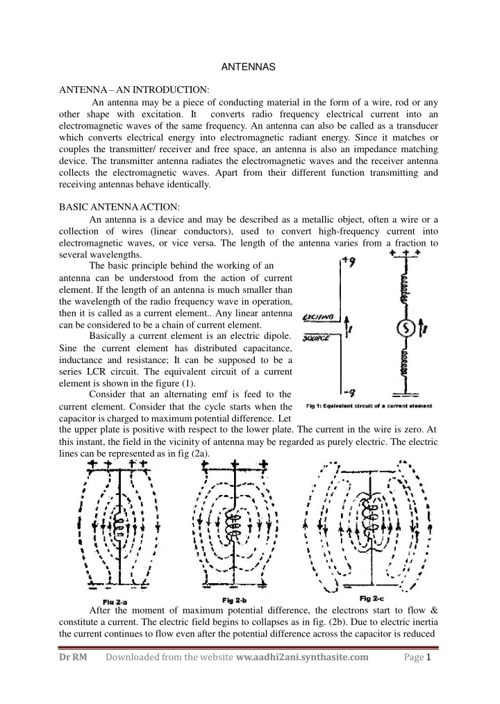
More Related Content

giItT1WQy@!-/#giItT1WQy@!-/#giItT1WQy@!-/#giItT1WQy@!-/#giItT1WQy@!-/#giItT1WQy@!-/#giItT1WQy@!-/#giItT1WQy@!-/#giItT1WQy@!-/#giItT1WQy@!-/#