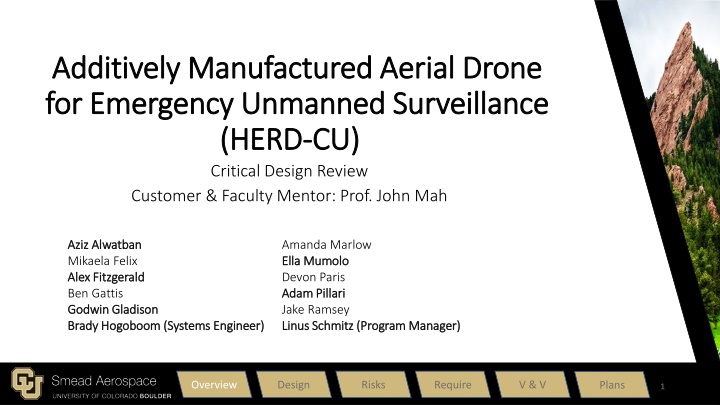
AMADEUS - Additively Manufactured Aerial Drone for Emergency Unmanned Surveillance
AMADEUS aims to provide a low-cost, high-endurance, human-portable, and rapidly deployable unmanned aerial system (UAS) for various missions in challenging environments. Designed for aerial surveillance, search and rescue operations, and more, it features functional and driving design requirements to ensure operational efficiency and compliance with regulations.
Download Presentation

Please find below an Image/Link to download the presentation.
The content on the website is provided AS IS for your information and personal use only. It may not be sold, licensed, or shared on other websites without obtaining consent from the author.If you encounter any issues during the download, it is possible that the publisher has removed the file from their server.
You are allowed to download the files provided on this website for personal or commercial use, subject to the condition that they are used lawfully. All files are the property of their respective owners.
The content on the website is provided AS IS for your information and personal use only. It may not be sold, licensed, or shared on other websites without obtaining consent from the author.
E N D
Presentation Transcript
Additively Manufactured Aerial Drone Additively Manufactured Aerial Drone for Emergency Unmanned Surveillance for Emergency Unmanned Surveillance (HERD (HERD- -CU) Critical Design Review Customer & Faculty Mentor: Prof. John Mah CU) Aziz Aziz Alwatban Alwatban Mikaela Felix Alex Fitzgerald Alex Fitzgerald Ben Gattis Godwin Godwin Gladison Gladison Brady Brady Hogoboom Hogoboom (Systems Engineer) (Systems Engineer) Amanda Marlow Ella Mumolo Ella Mumolo Devon Paris Adam Adam Pillari Pillari Jake Ramsey Linus Schmitz (Program Manager) Linus Schmitz (Program Manager) Overview Design Risks Require V & V Plans 1
Project Description The purpose of AMADEUS is to provide a low cost, high endurance, human portable, and rapidly deployable UAS capable of various missions in austere environments. Missions could include: Arial radio/cell repeater Search and rescue Reconnaissance Basic overwatch platform with camera Use in Fire departments, SAR, Military and other government agencies Overview Design Risks Require V & V Plans 2
CONOPS Overview Design Risks Require V & V Plans 3
Mission Profile 3. Orbit/Operation Descent Landing Glide into landing, no capture mechanism or runway. Orbit/Operation Steady, level, unaccelerated flight 152.4 meters of descent Density modeled as constant [1.007] kg/m^3 Power requirement equal to takeoff. Takeoff Slingshot launcher [902] newtons of force experienced Minimum change in velocity [~19] m/s Density constant using operational altitude value of [1.007] kg/m^2 152.4 meters of climb Trim Angle: 2.44 degrees Velocity: 21 m/s Climb Unaccelerated climb at flight speed of [21] m/s (SLUF) No turn performance considered 2000 meters ASL ~ 6500 ft ASL Power requirement assumed to be the same as climb 2. Climb 4. Descent 1. Takeoff 5. Landing Overview Design Risks Require V & V Plans 4
Functional Requirements FR.1: The UAS shall be human portable. FR.2: The UAS shall support 12 hours of continuous coverage/operation. FR.3: The UAS shall be durable to support structural loading and environmental conditions. FR.4: The UAS shall support a modular payload. FR.5: The UAS shall be low cost to produce and repair for user. FR.6: The UAS shall be rapidly deployable. FR.7: The UAS shall obey guidelines and regulations set forth by FAA and MIL-F-8785C. FR.8: The total costs for development and technology shall not exceed $4000. FR.9: The UAS shall be controllable by remote user. Overview Design Risks Require V & V Plans 5
Driving Design Requirements DR 1.2: Wingspan shall not exceed [3.6] meters. From portability and structural support (FR. 1). DR 1.3: Aircraft shall have detachable wings. From portability and manufacturing (FR. 1 and FR. 5) DR 2.1.1: The UAV shall have an operational endurance of [1.5] hours as a threshold, [4] hours as a goal. From aerodynamic efficiency and performance (FR. 2). DR 7.1: Aircraft airborne weight shall not exceed [20] kg as a threshold, [12] kg as a goal. Defined by ability for users to carry and FAA restrictions (FR. 7) Overview Design Risks Require V & V Plans 6
Single battery pack to power all aircraft systems Payload & battery are the two heaviest items on the aircraft one GPS & ground controller receivers Detachable wings Motor is largest power draw Large propeller to maximize efficiency ESC & BEC built into lessen complexity accurate airspeed Ground autopilot & computer Simple flight surfaces. Yaw, roll & pitch control Connected elevators to Pitot tube for more controller Flight computer for autopilot, navigation & control Ground flight Autopilot (COTS) will also help with stability Overview Design Risks Require V & V Plans 7
Design Solution - Aerodynamics Root Characteristics NACA 4412 0.3 meter chord Tip Characteristics NACA 0012 0.2 meter chord Wingspan: 3.6 meters Limited by structural spar beam size Horizontal Tail (NACA 0012) Chord Length: 0.1 m Tip to Tip Span: 0.814 m Vertical Tail (NACA 0012) Chord Length: 0.15 m Height: 0.36 m Overview Design Risks Require V & V Plans 8
Design Solution - Airframe Materials and Components Off-the-shelf carbon fiber beams Hex Fabric Tube 22 mm OD Pultruded Unidirectional Rod 12 mm OD Square Fabric Tube 22x25 mm Pultruded Unidirectional Rod 7.9 mm OD All other structures will be additively manufactured BCN3D/Prusa - dual extrusion FFM 3D printer Light Weight PLA Density can be adjusted using nozzle temperature to optimize strength and mass distribution Overview Design Risks Require V & V Plans 9
Design Solution - Airframe Overview Design Risks Require V & V Plans 10
Design Solution - Propulsion Motor HackerMotors A50 Max Power: 1250 W 520 kv 5S battery req 18.5 V Max draw < 70 A Propeller APC 16x14 84% efficiency @ orbit conditions Speed Controller HackerMotors MasterBasic 70SB Supports 70A, 6-26V continuous draw 5.5V Switching BEC Overview Design Risks Require V & V Plans 11
Design Solution - Electronics MATEKSYS Digital Airspeed Sensor Hitec HS-125MG Thin Metal Wing Servo Foxeer Falkor 3 Micro FPV Camera KOHD KOPILOT Lite Autopilot System Overview Design Risks Require V & V Plans 12
Design Solution Battery Battery Spec Value LiPo 23000 5S 18.5v Battery Pack Nominal Voltage 18.5 V Nominal Capacity 23,000 mAh Usable Capacity 20,700 mAh C Rating (Discharge rate) 25 C Total Energy 425.5 Wh Total Usable Energy 382.95 Wh Mass 2.071 kg Overview Design Risks Require V & V Plans 13
Design Solution - Launch System Elastic Energy Model: Assume friction with table/support negligible. Fundamental Model: K = 40.1 N/m (for 3m unstretched cord) Max Force experienced: 902 [N] Minimum velocity = Stall Velocity * (1.2) = 18.72 m/s Launcher Construction: Kent Elastomer surgical latex tubing Internal Diameter: 3/4 inch Width: 1/8 inch Two 3/4 inch steel posts to hold elastic Basic picnic table or something similar Overview Design Risks Require V & V Plans 14
Payload + Propulsion Payload Motor (A50-14 XS V4 kv520 ) Propeller Airframe/Structure Fuselage Wing Spars Fuselage Beam Wing Shell Horizontal Tail Spar Vertical Tail Spar Tail Shell Avionics + Electronics Battery (LiPo 23000 5S 18.5V Battery Pack) Camera (Foxeer Falkor 3 Micro 1200TVL M12 1.7mm) ESC (YEP 100A Brushless ESC) Autopilot (ZOHD KOPILOT Lite) Servos (HS-125MG Servo) Mass (kg) Mass Budget - UAV 3 0.347 0.051 Mass (kg) 2 Subsystem Propulsion Payload Airframe/Structure Electronics Total Margin Total Mass + Margin of 15% to account for adhesive, wiring, etc. Mass (kg) 0.823 0.36 1.2 0.0306 0.0306 0.61095 0.398 3 5.05 2.55 10.99 1.65 Mass (kg) 2.1 0.25 0.08 0.02 0.096 12.65 Overview Design Risks Require V & V Plans 15
Design Solution - Summary Physical characteristics: Total Aircraft Weight: 12.65 kg Wingspan: 3.6 m Length: 1.75 m Height: 0.534 m Max Payload: 3 kg Additional Components: Launcher UAS controller Autopilot computer Total Cost for project: $2790.32 Flight characteristics: Cruise speed: 21 m/s Endurance: 0:50 hrs Overview Design Risks Require V & V Plans 16
Critical Project Elements Aerodynamic Efficiency + Performance Structural Support Materials Portability FR.2 + FR.6 FR.1, FR.3 through FR.8 FR.3, FR.5, and FR.8 FR.1, FR.6 and FR.9 Interdependent with structures, aerodynamics and portability Interdependent with Structural support, materials, and aerodynamic efficiency Interdependent with materials and portability Interdependent with materials and portability Requirements/scope from iron triangle Scope, cost, and schedule from iron triangle Cost and requirements from iron triangle Requirements from iron triangle Overview Design Risks Require V & V Plans 17
Risk Analysis + Mitigation Risk If/Then Statement Probability Consequence Mitigation Strategy Aircraft Stall (8) If the UAV encounters stall conditions and recovery is not possible, then system will crash. 4 5 Increase margins between operational and stall conditions - Velocity: 15.6 vs. 21 m/s - Angle of attack: 2.44 vs. 10 degrees Modular Assembly (4) If the system is modular and assembled in the field, then connection between wing and fuselage introduces stress concentration. 4 4 "Wing box" design - 2 separate spar beams that connect fuselage and wing - Continuous spars, not modular. Manufacturing Time (14) If the system is to be 3D printed, then prints (components, elements, etc.) will have to be printed several times to account for deficiencies, testing, and design adjustments. 4 3 Advance Planning - Begin prints for testing early January - Account for extra printing material in cost plan Overview Design Risks Require V & V Plans 18
Aircraft Stall Limits Simulated stall conditions over aircraft main wing Main wing stall causes loss of aerodynamic lifting Low Reynold's Number effects increases the stall risk Main wing stall occurs at ~10 degrees angle of attack Aircraft main wing pressure contours with increasing angle of attack Overview Design Risks Require V & V Plans 19
Risk Matrix Consequence 1 2 3 4 5 5 1. Orbit Swapping 2. Engine Damage 3. Motor Failure 4. Modular Assembly 5. Control Communications 6. Factor of Safety (Wing Loading) 7. Aerodynamic Efficiency 8. Aircraft Stall 9. Battery Performance 10. Aircraft Stability 11. Launch Mechanism 12. Launch Pilot Training 13. Control Software Integration 14. Manufacturing Time 4 #12 #14 #4 #8 Probability of Occurrence 3 #1,3 #7, 13 2 #9 #11 #2 1 #10 #5 #6 Overview Design Risks Require V & V Plans 20
Design Requirements Satisfaction Overview Design Risks Require V & V Plans 21
Endurance Model DR 2.1.1 UAV shall have an operational endurance of [1.5] hours as a threshold, [4] hours as a goal. Assumptions: Motor efficiency = 0.8 Propeller efficiency = 0.84 Climb occurring at fixed speed Operational velocity of 21 m/s Span efficiency factor: e = 0.4 Zero lift angle = ??0 = -2.885 Method: Found energy required for takeoff, climb, orbit, descent, and landing Compared various models for climb and orbit, then took maximum energy requirement from those Used this to determine necessary specs for battery and power system Overview Design Risks Require V & V Plans 22
Aerodynamic Characterization Aircraft Coefficient of Lift Curve vs. Angle of Attack Aircraft Drag Polar Overview Design Risks Require V & V Plans 23
Endurance Model DR 2.1.1 UAV shall have an operational endurance of [1.5] hours as a threshold, [4] hours as a goal. Mission Energy = Takeoff + Climb + Orbit/Operation + Descent + Landing = 298 ~ 488 Wh Battery Energy = 425.5 Wh Rt = battery hour rating [hours] V = volts C = battery capacity [Amp-hours] U = velocity S = reference area W = weight n = discharge parameter = total efficiency For orbit/operation: Endurance = Predicted flight time = 0.8339 hours = 50 minutes = density = zero lift drag Overview Design Risks Require V & V Plans 24
Wing Bending Model DR 3.3: The UAV shall support wing loading of up to [13.33 ] with a safety factor of [1.3] Assumptions: Distributed load Fixed at Fuselage Small Bending Approximation All load is applied to spar beams Wing Structure deforms with the spar beams Dimensions Constraints Airfoil size given by aero Available beams produced by Rockwest Direct effect on mass Overview Design Risks Require V & V Plans 25
Wing Bending Model DR 3.3: The UAV shall support wing loading of up to [13.33 ] with a safety factor of [1.3] Curvature (k) can be related to the stress in the individual spars and the wing shell via the equation: where E is Young's Modulus and y is distance from cross section centroid. Min Wing Shell FOS = 1.3 Min Long Spar FOS = 19.6 Min Short Spar FOS = 27.3 Max Wing Deflection = 28.5 cm Overview Design Risks Require V & V Plans 26
Wing Bending Model DR 3.3: The UAV shall support wing loading of up to [13.33 ] with a safety factor of [1.3] Dimensions Max diameter/height = 2.94 cm Cross-Section Shape (Short Spar) Hollow Circle Hollow Square/Rectangle Hollow Hexagon Oval/Circle Parabolic distributed load Changed from one beam to two beams Short Spar Performance: The Hollow Hexagon geometry was chosen due to: Provided most support to the wing root Low cost Flat surfaces for potential fastening Factor of Safety (Wing Shell) Factor of Safety (CF Spar) Shape Hollow Circle 1.45 27.35 Hollow Square 1.35 25.32 Hollow Hexagon 1.46 27.35 Filled Circle 0.74 13.91 Above results were calculated based off of existing COTS spars with similar masses that met sizing constraints. Overview Design Risks Require V & V Plans 27
Wing Bending Model DR 3.3: The UAV shall support wing loading of up to [13.33 ] with a safety factor of [1.3] Long Spar Short Spar Geometry: OD: 1.198 cm Length: 1.8m Weight: 0.315 kg each Quantity: 2 total (1 per wing) Geometry: OD: 2.197 cm ID: 1.905 cm Length: 0.667 m Weight: 0.191 kg Quantity: 1 total Overview Design Risks Require V & V Plans 28
Verification and Validation Overview Design Risks Require V & V Plans 29
Whiffletree Test Objective Show that the wing can withstand expected worst case loading Determine if the wing behaves in a way consistent with model Requirement Verified DR 3.3: The UAV shall support wing loading of up to 13.33 kg/m^2 with a safety factor of 1.3 Overview Design Risks Require V & V Plans 30
*Representative whiffletree not actual configuration Whiffletree Test Equipment necessary Whiffle tree bars provided by Professor Schwartz Clamps Container + weights to fill it with 50 lb fishing line Slow motion cell phone camera with steady mount Ruler Plan/method: Calculate distances to approximate expected aerodynamic load distribution Apply 16 point loads over the 1.8m Account for weight of the bars themselves Print a fuselage section and wing to test to failure along with an extra set of wing spars Clamp fuselage in place upside-down & attach wing Load weights incrementally into container until failure Overview Design Risks Require V & V Plans 31
*Representative whiffletree not actual configuration Whiffletree Test Measurements to collect Total deflection Use camera and ruler Load applied at failure Count weights Pass Criteria: 1. Wing holds 16.7 kg with no perceivable failure (meets requirements) 2. Total deflection below 0.286 m with a load of 16.7 kg (behaves as predicted) Overview Design Risks Require V & V Plans 32
Motor Static Test Objective: Obtain thrust data from chosen motor and propeller Measurements to collect: Thrust at various RPM -> system efficiency Requirement(s) Verified: DR 2.1.1.4: The UAV propulsion system shall provide a minimum of 10.41 [N] of thrust in orbit. The motor can obtain desired RPM for climb and orbit Motor is compatible with the battery voltage and current output Overview Design Risks Require V & V Plans 33
Motor Static Test Plan/method: Thrust setup will be placed on a static test stand Load cells will be used to measure the force the propeller outputs from the RPM Pass Criteria: The motor and propeller setup will output desired thrust force at a reasonable RPM Voltage and current draw from the battery is within model limits Similar setup to Talon Static test stand Overview Design Risks Require V & V Plans 34
Motor Static Test Materials needed: Static test stand Load cells and data acquisition device Motor and propeller Facilities necessary: DBF Static Test Stand (In Contact) Wind tunnel for accurate thrust measurements Blockers and/or safety concerns: Propeller and motor would need to be compatible Durability of the Overview Design Risks Require V & V Plans 35
Full Flight Test Plan/method Glide at different angles of attack Back out lift to drag ratio from flight data Return lift and drag separately to verify model accuracy Pass Criteria Model accuracy matches experimental results within 10% Aircraft maintains flight and stability during test Overview Design Risks Require V & V Plans 36
Full Flight Test Materials needed Full aircraft needs to be built and inspected for safety Facilities necessary Large open area with free airspace for safe operation Safety Considerations and Possible Obstacles Requires an FAA certified drone pilot Likely will be from the potential customer, BES Required to follow all FAA operating procedures for unmanned aerial systems under 14 CFR Part 107 Lithium-Ion batteries can pose a large danger in any system failure Fire extinguishers and other safety measures must be readily available Requires a clear weather window and a low risk of wildfires Overview Design Risks Require V & V Plans 37
Safety Concerns The following tests will require procedures to ensure safety Launch system Materials Testing Flight Testing Battery Endurance Human Portability Other safety concerns Battery Charging procedures System Operation and Storage Procedures Overview Design Risks Require V & V Plans 38
Overview Design Risks Require V & V Plans 39
Overview Design Risks Require V & V Plans 40
Test Special Facilities + Equipment Flight Time Battery Test N/A Servo Functionality Test N/A Thrust + Efficiency Test - DPF Static Test Stand - Load cells and data acquisition device Electronics Ground Test N/A Whiffle Tree Test Whiffle Tree equipment; in contact with Prof. Schwartz Launch Velocity Test - Open space Full Flight Test - FAA certified drone pilot; BES customer. - Open space Overview Design Risks Require V & V Plans 41
Cost Plan Structural Total: $1550.03 Propulsion Total: $959.34 Electronics Total: $280.95 Current Margin (may Decrease): 43.35% ($1209.68) Awaiting EEF Mini Approval EEF Mini Funding Request: $2413.54 Overview Design Risks Require V & V Plans 42
Overview Design Risks Require V & V Plans 43
Question? * Any slides with animations are included in the backup slides as individuals for later reference*
Main Slide Reference Purpose and Objectives Whiffletree Test: Equipment (31) Purpose & Objectives (2) Critical Project Elements & Risks Whiffletree Test: Measurements (32) CONOPS (3) CPEs (17) Motor Static Test: Objectives (33) Mission Profile (4) Risk Analysis + Mitigation (18) Motor Static Test: Measurements (34) Design Solution Aircraft Stall Limits (19) Motor Static Test: Equipment (35) Functional Requirements (5) Risk Matrix (20) Full Flight Test: Objectives (36) Design Requirements (6) Design Requirements Satisfaction Full Flight Test: Equipment (37) Functional Block Diagram (7) Endurance Model (22) Safety Concerns (38) Design Solution Aerodynamics (8) Aerodynamic Characterization (23) Project Planning Design Solution Airframe (9-10) Endurance Model Equations (24) WBS (39) Design Solution Propulsion (11) Wing Bending Model: Assumptions (25) Gantt Chart (40) Design Solution Electronics (12) Wing Bending Model: Deflection (26) Manufacturing & Testing Plans (41) Design Solution Battery (13) Wing Bending Model: Spar (27) Cost Plan (42) Design Solution - Launch System (14) Wing Bending Model: Choices (28) Organizational Chart (43) Mass Budget (15) Verification and Validation Design Solution Summary (16) Whiffletree Test: Objectives (30) Overview Design Risks Require V & V Plans 45
CDR Backup Slide Reference Purpose and Objectives Mass Budget Mission Profile Animation Breakdown Digital Design Parameters Design Solution Functional Block Diagram Design Requirements - 1,2 & 3 ANSYS Fluent Modelling FBD Animation Breakdown Lift and Drag Component Breakdown FBD Electronic Components Critical Project Elements & Risks FBD Electronics Connections Risk Matrix Scoring Analysis (47) Launch System Animation Breakdown -1 & 2 Launch System Math -1, 2 & 3 Launch System Video Risks Physical Design Parameters 46
BACKUP SLIDE Natural Stability Requirements Pitch Stability Requirement Pitching moment must tend to counteract aircraft motion Restores aircraft to its natural trim position Center of gravity balance and static margin limitations Horizontal tail to provide pitching moment balance Yaw Stability Requirement Vertical tail weathervane effect to keep aircraft flying true straight Roll Stability Requirement Natural restoration to level flight trim Ability to hold roll angle through turn maneuvers Overview Design Risks Require V & V Plans 47
BACKUP SLIDE Static Margin Model SM = (XNP-XCG)/MAC = %14.2 (with payload) SM = %16.99 (no payload) Overview Design Risks Require V & V Plans 48
Maybe BACKUP SLIDE Endurance Model Aerodynamics DR 2.1.1 UAV shall have an operational endurance of [1.5] hours as a threshold, [4] hours as a goal. Exploration of trim conditions to maximize endurance Minimum Power Required Induced drag is 3x parasite drag Trim location would be past stall limits Maximum Lift to Drag Tangent line from origin to drag polar Very small margin between stall and trim Selected Trim Condition Fly near maximum efficiency to safely avoid aircraft stall Keep velocity as low as possible to avoid excess power drain At xx m/s at -- angle Overview Design Risks Require V & V Plans 49
Maybe BACKUP SLIDE Endurance: Optimizing Propulsion System Goals: Optimize motor and propeller for cruise flight conditions -From aerodynamics: Velocity = 21m/s, Drag = 8.81 N -Cruise power required: 275 W -Climb power required: 400 W Propeller Solution: 16x14 APC Prop -> @4000rpm, 21m/s, 9.8 N of thrust with 84% efficiency Motor Solution: HackerMotors A50 -> Max power 1250W, 520 kv, 5S 18.5V battery required Overview Design Risks Require V & V Plans 50
