Acceleration Analysis of Slider Crank Mechanism
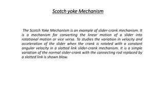
In this analysis, we calculate the acceleration of the slider at point B, acceleration of point E, and the angular acceleration of the link AB in a slider crank mechanism. The steps involve drawing configuration, velocity, and acceleration diagrams with suitable scales to determine the necessary parameters for the mechanism.
Download Presentation

Please find below an Image/Link to download the presentation.
The content on the website is provided AS IS for your information and personal use only. It may not be sold, licensed, or shared on other websites without obtaining consent from the author.If you encounter any issues during the download, it is possible that the publisher has removed the file from their server.
You are allowed to download the files provided on this website for personal or commercial use, subject to the condition that they are used lawfully. All files are the property of their respective owners.
The content on the website is provided AS IS for your information and personal use only. It may not be sold, licensed, or shared on other websites without obtaining consent from the author.
E N D
Presentation Transcript
Acceleration analysis Problem-1: For the configuration of a slider crank mechanism, calculate the (a) acceleration of the slider at B (b) acceleration of the point E (c) angular acceleration of the link AB OA rotates at 20 rad/s counter-clockwise Step -1: Draw Configuration Diagram with suitable scale Step -2: Draw Velocity diagram and find the angular velocity of link AB Step -3: Draw acceleration diagram and find the acceleration of point B, angular acceleration of link AB.
Step -1: Draw Configuration Diagram with suitable scale Define suitable scale for drawing configuration scale Let 480 mm = 2 inch Actual dimension Drawing dimension OA 480 mm 1.5 inch AB 1600 mm 5 inch AE 450 mm 1.40625 inch A O DO Your SELF
Step -1: Draw Configuration Diagram with suitable scale A O B This is the circle of radius 1600 mm (5 inch)
Step -1: Draw Configuration Diagram with suitable scale A 1600 480 600 O B Configuration diagram
Step -2: Velocity Diagram A 1600 480 600 O B Given, (i) OA = 20 rad/s (counter clockwise) Velocity of point A: Magnitude: VA/O = OA x OA = 20 rad/s x 0.48 m = 9.6 m/s Direction: velocity of A is perpendicular to OA Define Scale Let 9.6 m/s = 2.5 inch a Angular speed of Link OA, 2.5 inch o , g b a 2.5 inch 1.3 inch Draw velocity vector VA o , g b 2.4 inch
Step -2: Velocity Diagram A 1600 480 600 O B a Given, (i) OA = 20 rad/s (counter clockwise) Velocity of point A: Magnitude: VA/O = OA x OA = 20 rad/s x 0.48 m = 9.6 m/s Direction: velocity of A is perpendicular to OA Define Scale Let 9.6 m/s = 2.5 inch Angular speed of Link OA, 2.5 inch 1.3 inch o , g b 2.4 inch a 2.5 inch 1.3 inch o , g Draw velocity vector VA b 2.4 inch
Step -2: Velocity Diagram a 2.5 inch 1.3 inch o , g b 2.4 inch Velocity Diagram Define Scale Let 9.6 m/s = 2.5 inch Drawing scale Actual scale oa 2.5 inch 9.6 m/s Velocity of point A ab 1.3 inch 4.992 m/s Velocity of B with respect A ob 2.4 inch 9.216 m/s Velocity of B Angular speed of AB 3.12 rad/s Angular speed of AB
Step -3: Acceleration diagram A 1600 480 600 O B Configuration diagram a Drawing scale Actual scale 2.5 inch oa 2.5 inch 9.6 m/s 1.3 inch Velocity of point A ab 1.3 inch 4.992 m/s Velocity of B with respect A ob 2.4 inch 9.216 m/s Velocity of B o , g b 2.4 inch Velocity Diagram 3.12 rad/s Angular speed of AB Acceleration of A Magnitude: Direction: Along AO direction point towards O Define Scale for acceleration diagram Let 192 m/s2 = 2.5 inch
Step -3: Acceleration diagram A 1600 aA 480 600 O B Configuration diagram b) Draw acceleration of point B Direction : Horizontal Define Scale for acceleration diagram Let 192 m/s2 = 2 inch Locus of point b Draw acceleration diagram (a) Draw acceleration of point A (o, g) (o, g) 2 inch 2 inch a a
Step -3: Acceleration diagram A AB2 AB 1600 aA 480 radial components 600 O aA B Configuration diagram aB/A b) Draw acceleration of point B Direction : Horizontal aB = aA + aB/A tangential components. AB Locus of point b acceleration of B with respect to A, it contains two components (i) Along BA (ii) Perpendicular to BA (o, g) 2 inch (i) Component of Acceleration of B with respect to A along BA is known as radial components. (ii) Component of Acceleration of B with respect to A perpendicular to BA is known as tangential components. a
Step -3: Acceleration diagram A aB/Ar AB2 AB 1600 aA 480 radial components 600 O aA B Configuration diagram aB/A Define Scale for acceleration diagram Let 192 m/s2 = 2 inch x m/s2 = ?? Inch aB/At tangential components. AB Locus of point b Ob inch = ?? = acceleration B aB b 3.12 rad/s (o, g) Angular speed of AB aB/A aB/At aA 2 inch AB2 AB aB/Ar aB/At ?? incht ?? inch a x m/s2 AB2 AB AB = ?? m/s2 aB/At = ?? m/s2
