6.0 METER KUASA
Power meters play a crucial role in measuring electrical power. They consider both voltage and current to determine the power in watts or kilowatts. Learn about different types of power meters and basic principles in power measurement.

Uploaded on Feb 20, 2025 | 1 Views
Download Presentation

Please find below an Image/Link to download the presentation.
The content on the website is provided AS IS for your information and personal use only. It may not be sold, licensed, or shared on other websites without obtaining consent from the author.If you encounter any issues during the download, it is possible that the publisher has removed the file from their server.
You are allowed to download the files provided on this website for personal or commercial use, subject to the condition that they are used lawfully. All files are the property of their respective owners.
The content on the website is provided AS IS for your information and personal use only. It may not be sold, licensed, or shared on other websites without obtaining consent from the author.
E N D
Presentation Transcript
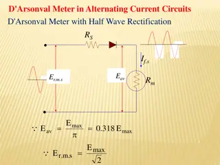
6.1 PRINSIP ASAS METER KUASA Kuasa dalam litar elektrik ialah hasil (pendaraban) voltan dan arus, jadi mana-mana meter yang direka untuk mengukur kuasa mesti mengambil kira kedua- dua pembolehubah ini. Kuasa diukur dalam Watt (atau kilowatt). Meter kuasa ialah meter bagi mengukur jumlah kuasa elektrik yang digunakan. Terdapat banyak jenis Meter Kuasa seperti Wattmeter, KWH meter, Clamp meter dan lain-lain.
Jenis-jenis Meter Kuasa (A,B,C-Meter kWj, D- Wattmeter, E- Clamp meter).
Tiga persamaan kuasa dalam litar yang dikenali sebagai hukum Wat: 2 V P IV = = P I , , = 2R P R
Contoh 1: Apakah kuasa yang terlesap oleh pemanas yang menarik 12 A arus daripada bekalan 120 V? Penyelesaian: = = = P IV ( 1440 W )( ) 12 A 120 V
Contoh 2: Apakah kuasa yang terlesap dalam perintang 27 Ohm jika arus ialah 0.135 A? Penyelesaian: = = = 2 P I R ( ) 2 (0.135 A) 0.49 W 27
6.1.1 RAJAH BINAAN METER KUASA Litar elektrodynamometer wattmeter
Wattmeter analog tradisional ialah instrumen elektrodinamik. Peranti terdiri daripada: *sepasang gegelung tetap, (dikenali sebagai gegelung arus) *gegelung boleh alih (dikenali sebagai gegelung voltan)
6.1.2 PRINSIP KENDALIAN WATTMETER Gegelung arus disambung secara sesiri dengan litar, manakala gegelung voltan disambung selari dengan litar. Apabila arus mengalir melalui gegelung arus,medan elektromagnet terjana di sekeliling gegelung. Kekuatan medan ini adalah berkadaran dengan arus talian dan sefasa dengannya.
Gegelung voltan membawa jarum yang bergerak pada skala bagi menunjukkan ukuran Gegelung voltan meter watt biasanya mempunyai perintang rintangan tinggi yang disambungkan secara sesiri (untuk mengurangkan arus yang mengalir melaluinya) Hasil daripada susunan ini pada litar dc, pesongan jarum adalah berkadaran dengan arus dan voltan dengan itu menepati persamaan P =IV.
6.1.3 SAMBUNGAN WATTMETER UNTUK PENGUKURAN KUASA Sambungan Wattmeter dalam litar satu fasa.
GEGELUNG VOLTAN DAN GEGELUNG ARUS BAGI WATTMETER Dua mekanisme utama wattmeter ialah: i. Banyak lilitan wayar halus yang disarungkan dalam plastik yang disambungkan selari dengan beban. Gegelung voltan ii. Gegelung arus Tiga lilitan wayar tebal, disambung secara sesiri dengan beban.
6.2.1 CONSTRUCTION OF KWH METER Analog : Construction of Kilowatt-hour meter
THE CONSTRUCTION OF KWH METER A single phase induction type energy meter consists of driving system, moving system, braking system and registering system.
6.2.2 THE BASIC PRINCIPLE OF ANALOGUE KWH METER The Kilowatt-hour meter is an instrument for measuring the amount of electrical energy consumed by a residence, business, or an electrically powered device. Energy = Power x time ( joules ) Kilowatt hour is most commonly known as a billing unit for energy delivered to consumers by electric utilitie. In principle, the watt-hour meter is a small motor whose instantaneous speed is proportional to the power passing through it.
The total revolutions in a given time are proportional to the total energy or watt-hour, consumed during that time. The current coil is connected in series with the line and the voltage coil is connected across the line. Both coil are wound on a metal frame of special design, providing two magnetic circuits. A light aluminium disk is suspended in the air gap of current coil field, which cause eddy currents flow in the disc.
(A) DRIVING SYSTEM Driving system of the energy meter consists of two silicon steel laminated electromagnets. Referring figure 5.4,the electromagnet M1 is called the series magnet or current coil (CC) and the electromagnet M2 is called the shunt magnet or voltage coil (VC) . The current coil carries a coil consisting of a few turns of thick wire and it is connected in series with the circuit. The load current flows through this coil. The voltage coil carries a coil consisting many turns of thin wire and it is connected across the supply.
(B) MOVING SYSTEM The moving system consists of a thin aluminum disc mounted on a spindle and is placed in the air gap between the series and the shunt magnets. It cuts the flux of both the magnet forces are produced by the fluxes of M1 & M2 . Both these forces act on the disc. These two forces constitute a deflecting torque.
(C) BRAKING SYSTEM The braking system consists of a permanent magnet called brake magnet. Provides necessary braking torque which opposes the motion of disc.
(D) REGISTERING SYSTEM The disc spindle is connected to a counting mechanism this mechanism records a number which is proportional to the number of revolutions of the disc. The counter is calibrated to indicate the energy consumed directly in kilo watts-hour (KWH)
6.2.3 THE CONSTRUCT KWH CONNECTION FOR ELECTRICAL ENERGY MEASUREMENT Main (input): Voltage source Load: Lamp,Fan
TUTORIAL 1. A meter which is used to measure the amount of electric power is known as __________. A. Ammeter C. Ohmmeter B. Power meter D. Voltmeter 2. A _____________ is a type of meter which measures electrical current without need to disconnect the wiring through which the current is flowing. A. Ammeter B. Power meter C. Clamp meter D. Watt meter
3. Wattmeter is built based on i. ii. iii. iv. Copper loop Current loop Voltage loop. Power loop A. i, ii B. ii, iii C. iii, iv D. iv, i
4. a. Draw the connection of Wattmeter for power measurement. b. Name THREE (3) mechanisms of electromechanical induction meter in watt- hour meter ? 5. Calculate the Power Consumption in the system with the voltage is 35.5V and the current is 1.25A.
TUTORIAL ANSWER 1) 2) 3) B C B 4a) 4b) Driving system, Moving system, Braking system, Registering system. 5) P= 44.375W.
REFERENCES Kalsi, H.S. (2004). Electronic Instrumentation. New Delhi: Tata McGraw-Hill. Bakshi U.A, Bakshi A.V. (2009). Electronic Instrumentation, Technical Publications, Bhavani V, Vasantha S. (2008). Measurements & Instrumentation, IBS Helfrick & Cooper (2008). Modern Electronic Instrumentation & Measurement Techniques, Prentice Hall of India Stephen L.Herman (2010) .Standard Textbook of Electricity, 5th Edition. Delmar Cengage Learning


 DRIVING SYSTEM")
 MOVING SYSTEM")
 BRAKING SYSTEM")
 REGISTERING SYSTEM")