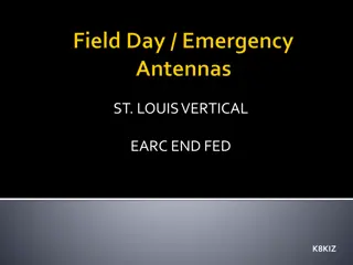
Building a 40-Meter Turnstyle Antenna: Step-by-Step Guide
Learn how to construct a 40-meter turnstile antenna for improved signal coverage using detailed instructions, diagrams, and recommended coaxial cables. Discover the materials needed, calculate dipole lengths, set up the phasing line, and optimize performance for HF frequencies.

Download Presentation

Please find below an Image/Link to download the presentation.
The content on the website is provided AS IS for your information and personal use only. It may not be sold, licensed, or shared on other websites without obtaining consent from the author.If you encounter any issues during the download, it is possible that the publisher has removed the file from their server.
You are allowed to download the files provided on this website for personal or commercial use, subject to the condition that they are used lawfully. All files are the property of their respective owners.
The content on the website is provided AS IS for your information and personal use only. It may not be sold, licensed, or shared on other websites without obtaining consent from the author.
E N D
Presentation Transcript
The Turnstyle Antenna 40 meter version
THE TURNSTILE ANTENNA What is a turnstile antenna? It is an antenna which has two sets of dipoles aligned at right angles to each other and fed out of phase. The turnstile antenna is one antenna that ALMOST 360 DEGREE COVERAGE. Only a very little bit on each end around 2% has no coverage. The antenna today that I will be talking about is the 40 meter version with the centre frequency of 7.100 MHz. This antenna is a 1 band antenna or monoband however you can tune it up with an ATU for other bands above 7 MHz. Once you have established what frequency you are going to use you have to work out the length of each dipole. The formula that I use is unique. Instead of using 300 divided by the frequency I use 299/frequency. This gives me a figure to start at. The dipole lengths at this point are still longer than required. We will need 4 lengths. The next part of this antenna is make up the center section, and wind up the choke. ALL coaxial cable used in this antenna is 75 ohm RG-6. Except for the matching section which is RG-58AU.
There are 40 turns wrapped around a 50mm diameter former which is PVC pipe and 350 mm in length. You will also need a PVC box about 100 x 100 x 100 mm which is waterproof. A hole is required in which the PVC pipe is inserted and glued. Once that is done it is time to cut the coaxial cable to make the phasing line, matching section. See diagram below.
I have already calculated the measurements and the trimming of the dipoles still needs to be done. You might be thinking why are they using RG-6 cable? The answer is simple. Let s look at a coaxial chart.
So from the chart above you can see that at HF RG-6 has very little lose. I use RG-6 QUAD as it has very good earthing and cuts allot of noise out. However, the down side is that you can t solder it unless you may big bucks for the right solder or you buy the old copper wire RG-6 which is much more expensive than the aluminum variety. The connection points for the phasing and matching are in the diagram below.
Above are the two inside views where all the connections are made. You can see that I used crimp on connectors and joiners for ease of construction. However, you can use whatever method to connect the wires that you wish. You can see that there are 2 stainless steel rods passing through both of the centers. This is where all the strain is and the dipoles pass through the 4 eyelets and onto their connection points of the box. Now for the important part of the tuning process. Connect ONLY 2 wires of the 1st dipole on and tune as you would a normal dipole. Once you get it where you want it to resonant you have to take the wires OFF. Then connect the other side up and do it all again. It is very important that you make sure that no wires are touching inside the box otherwise you will get a short. Connections on the ends of the RG-6 are crimped on BNC connections or F connectors.
See diagram below. Be careful, to buy quality not quantity. Below are a number of connectors that you can use and the one that that I use mostly is the F connector to BNC or F connector to PL 259. See pics below. PL 259 to F connector.
BNC to F connector. Try to avoid F type connector joiners as I have found them to fail or fall apart.
Below is the radiation pattern and layout of the turnstile antenna.
The higher you get this antenna the better it will work. I use this antenna with the Port Stephens A.R.C. with great success. The question has been asked Can this antenna be used in a INVERTED VEE configuration? Well the answer is unknown but you can try it. You could get some funny radiation patterns. This antenna is intended to be used in a horizontal configuration. Have fun building this antenna. My thanks must go to Peter Mallon ( VK2BFQ) SK who did the calculations and help make this antenna.