Understanding Constructive Solid Geometry Concepts
Explore Constructive Solid Geometry (CSG) concepts including binary tree representation, Boolean operations, base feature selection in parametric modeling, and the importance of order in feature creation. Learn about CSG's role in representing solid models and its applications in the field of solid modeling.

Download Presentation

Please find below an Image/Link to download the presentation.
The content on the website is provided AS IS for your information and personal use only. It may not be sold, licensed, or shared on other websites without obtaining consent from the author. Download presentation by click this link. If you encounter any issues during the download, it is possible that the publisher has removed the file from their server.
E N D
Presentation Transcript
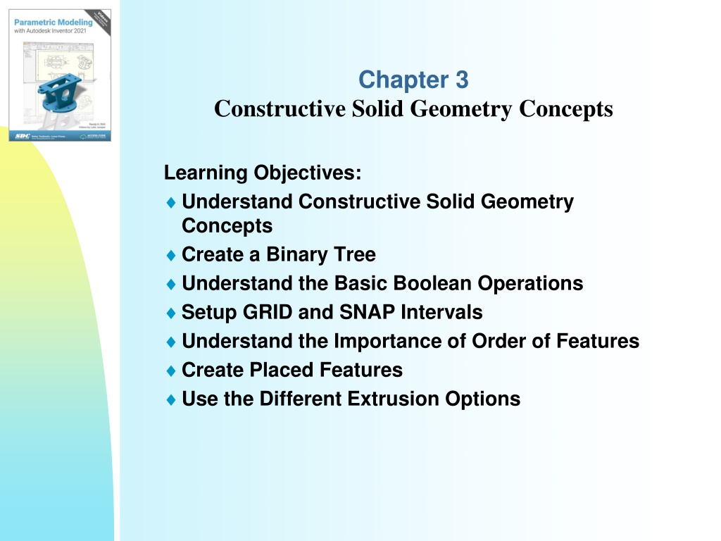
Chapter 3 Constructive Solid Geometry Concepts Learning Objectives: Understand Constructive Solid Geometry Concepts Create a Binary Tree Understand the Basic Boolean Operations Setup GRID and SNAP Intervals Understand the Importance of Order of Features Create Placed Features Use the Different Extrusion Options
Introduction In the 1980s, one of the main advancements in solid modeling was the development of the Constructive Solid Geometry (CSG) method. CSG describes the solid model as combinations of basic three-dimensional shapes (primitive solids). The basic primitive solid set typically includes: Rectangular-prism (Block), Cylinder, Cone, Sphere, and Torus (Tube). Two solid objects can be combined into one object in various ways using operations known as Boolean operations. There are three basic Boolean operations: JOIN (Union), CUT (Difference), and INTERSECT. The JOIN operation combines the two volumes included in the different solids into a single solid. The CUT operation subtracts the volume of one solid object from the other solid object. The INTERSECT operation keeps only the volume common to both solid objects. The CSG method is also known as the Machinist's Approach, as the method is parallel to machine shop practices.
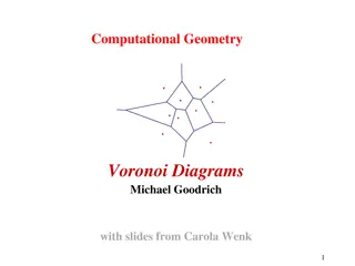
Binary Tree The CSG is also referred to as the method used to store a solid model in the database. The resulting solid can be easily represented by what is called a binary tree. In a binary tree, the terminal branches (leaves) are the various primitives that are linked together to make the final solid object (the root). The binary tree is an effective way to keep track of the history of the resulting solid. By keeping track of the history, the solid model can be re- built by re-linking through the binary tree.
Base Feature In parametric modeling, the first solid feature is called the base feature, which usually is the primary shape of the model. Depending upon the design intent, additional features are added to the base feature. Some of the considerations involved in selecting the base feature are: Design intent Determine the functionality of the design; identify the feature that is central to the design. Order of features Choose the feature that is the logical base in terms of the order of features in the design. Ease of making modifications Select a base feature that is more stable and is less likely to be changed.
Third Solid Feature CSG Cut
PLACED FEATURE In Autodesk Inventor, there are two types of geometric features: placed features and sketched features. The last cut feature we created is a sketched feature, where we created a rough sketch and performed an extrusion operation. We can also create a hole feature, which is a placed feature. A placed feature is a feature that does not need a sketch and can be created automatically. Holes, fillets, chamfers, and shells are all placed features.