A Closer Look at PEP-II IR Experience and Beam Parameters
Dive into the details of PEP-II IR layout, beam parameters, and differences/similarities with other accelerator designs like JLEIC and eRHIC. Explore topics such as beam-gas interactions, radiative Bhabhas, and detector acceptance angles, presented at the EIC User Meeting.

Download Presentation

Please find below an Image/Link to download the presentation.
The content on the website is provided AS IS for your information and personal use only. It may not be sold, licensed, or shared on other websites without obtaining consent from the author. Download presentation by click this link. If you encounter any issues during the download, it is possible that the publisher has removed the file from their server.
E N D
Presentation Transcript
PEP PEP- -II IR Experience II IR Experience Michael Sullivan SLAC National Accelerator Laboratory for the EIC User meeting Argonne National Laboratory Oct. 9-11
Outline Beam parameters PEP-II IR layout JLEIC layout eRHIC layout Differences and similarities Backgrounds SR Neutrons Beam-gas Radiative Bhabhas Zero-degree luminosity detector Summary 10/10/2019 EIC User Meeting 2
PEP-II beam Parameters The PEP acronym was originally Positron Electron Proton Circumference 2.2 km Electron (HEB) current 1.875 A Positron (LEB) current 2.900 A Number of bunches 1722 (every other rf bucket with a 24 bunch ion gap) Luminosity 1.2 1034 Maximum HEB current 2.069 A Maximum LEB current 3.216 A 10/10/2019 EIC User Meeting 3
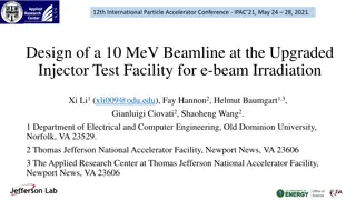
30 IR Layout BABAR Detector 3.1 GeV Q5 Q4 Q2 20 The beams are head-on at the collision point and the strongest bend magnets in the entire accelerator are the B1 bend magnets Q1 B1 10 X (cm) 9 GeV 0 Q1 quads are offset for the LEB and nearly centered for the HEB 9 GeV -10 Q4 quads are offset for the HEB B1 Q1 3.1 GeV -20 Q4 Q5 Q2 Details of the SR masking design can be seen in the beam pipe outline -30 -7.5 -5 -2.5 0 2.5 5 7.5 Z (m) M. Sullivan Feb. 8, 2004 API88k3_R5_RADBHA_TOT_7_5M 10/10/2019 EIC User Meeting 4
eRHIC and JLEIC IRs EIC at JLAB 50 mrad crossing angle EIC at BNL 25 mrad crossing angle 10/10/2019 EIC User Meeting 5
Differences and similarities Similarities Magnets are close to the IP Little or no pumping near the IP High beam currents Very crowded Differences Head-on vs crossing angle collision Strong bending near the IP vs little or no bending near the IP Upstream bending is far from the IP in the EIC designs Beam tail sensitivity very small for PEP-II vs much more important for EIC IR scrubbing time fast for PEP-II (lots of SR) vs slower for EIC designs (less SR) Very low angle detector acceptance (down to zero degrees) for EIC 10/10/2019 EIC User Meeting 6
Backgrounds SR The masking design in the PEP-II B-factory eliminated any direct hit from SR as well as any one-bounce hits (except for a small back- scatter rate from about 2.3 m) The remaining SR backgrounds came from mask tip scattering rates produced from incident bend radiation on the mask surfaces Hence the design was insensitive to any beam tail distribution The downstream double B1 fan from the HEB was absorbed on the beam pipe wall 10 to 20 m from the IP Up to 50 kW of SR power was in this overlapping fan The critical energy was about 40 keV (the magnet tapers somewhat) This turned out to be a source of neutrons for the detector 10/10/2019 EIC User Meeting 7
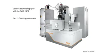
SR fans LER fans HER fans Up to 50 kW in this fan The downstream double fan of SR from the B1 magnets was absorbed on a Cu beam pipe wall between 10 and 20 m from the IP. This became a source of neutrons. 10/10/2019 EIC User Meeting 8
Beam tails Standard X beam tail Standard Y beam tail Plots of the halo beam tail used for most SR studies. The beam lifetime is about 10 min with a 15 x collimator and a 45 y collimator. 10/10/2019 EIC User Meeting 9
Backgrounds cont. Beam-gas PEP-II There were several bend magnets in the upstream beam lines to the IP The obvious close bend magnets (B1 and offset Q4) but also two soft bend magnets in the HEB The LEB had stronger bend magnets closer to the IP The LEB had to make a vertical step of 90 cm to get in the plane of the HEB The last vertical bend ended 10 m upstream of the IP and had a 4.753 kG field (22.8 mrad) It made a 4 kW SR fan, but the critical energy was only 3 keV EIC designs Both have little or no upstream bend magnets (very little beam pipe scrubbing) Need to have very good upstream vacuum (no bend fields to sweep out the locally generated BGB off-energy particles) 10/10/2019 EIC User Meeting 10
Backgrounds (still more) Radiative Bhabhas The PEP-II B-factory had a very significant radiative Bhabha background The very strong bending magnets (B1) located close to the IP ( 22 cm) started separating the off-energy beam particles from the rest of the beam and so they started to crash into the local beam pipe The KEKB design had only outgoing bend fields from the shared quadrupole magnets Hence the KEKB radiative Bhabha background was significantly smaller The EIC designs both have only outgoing bending ~10 m from the IP The EIC radiative Bhabha background will be much more like the KEKB observed background from this source 10/10/2019 EIC User Meeting 11
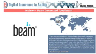
PEP-II Interaction Region HER Radiative bhabhas 30 2.5 3 3.5 3.1 GeV Radiative Bhabhas 4 20 1.5 2 1 0.5 10 LER gammas 6 6.5 4.5 5 cm 9 GeV 5.5 7 0 7.5 8 PEP-II radiative Bhabha energy distribution 9 GeV -10 HER gammas 0.5 21.51 The numbers are the beam particle energy in GeV 3.1 GeV -20 2.5 LER Radiative bhabhas 3 -30 -7.5 -5 -2.5 0 m 2.5 5 7.5 M. Sullivan Feb. 8, 2004 API88k3_R5_RADBHA_TOT_7_5M 10/10/2019 EIC User Meeting 12
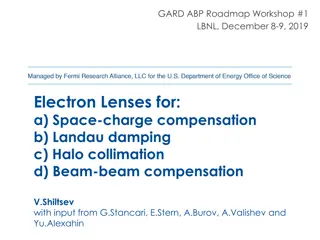
KEKB Interaction Region HER radiative bhabhas EIC is more like KEKB 30 6 7 5 Q1ER 4 1 LER radiative bhabhas Detector 2 Q2PL 3 20 1.5 1 0.5 QCSL 2.5 0.5 QCSR 3 2 HER radiative gammas CSL CSR 10 KEKB radiative Bhabha energy distribution cm LER radiative gammas 3.5 GeV 0 LER HER The EIC design is actually closer still to the superKEKB where all final focus quads are on axis (or nearly on axis) -10 8 GeV CSL CSR Q2PR QCSL QCSR -20 Q1EL Detector -30 -7.5 -5 -2.5 0 m 2.5 5 7.5 M. Sullivan Nov. 9, 2004 B3$KEK2_IR_RADBHA 10/10/2019 EIC User Meeting 13
Luminosity detector at zero degrees The PEP-II B-factory had a zero-degree luminosity detector primarily for the accelerator group The main detector used a Bhabha trigger to measure luminosity A zero-degree detector will also intercept the gammas from BGB events generated after the last bend magnet as well as any beamsstrahlung gammas as a background to the luminosity signal All of the upstream and downstream bend magnets in the PEP-II design reduced the BGB background of the luminosity signal to a length of beam trajectory of about 0.5 m The vacuum pressure was high at the IP (about 10-100 nTorr) but we were able to get a very clear luminosity signal for each collision We initially had ion pumps between B1 and Q1 but those failed after a couple of years 10/10/2019 EIC User Meeting 14
We chose to use the LER outgoing gammas for the luminosity detector. The LER SR fan critical energy is lower and the power in the overlapping fan is lower than the HER fan from the B1 magnets Luminosity detector Lumi detector 10/10/2019 EIC User Meeting 15
Summary The PEP-II B-factory was one of the first high-current colliders The head-on collision design is still unique This choice necessitated strong bending very near the IP All current and future collider designs (including the EIC) use a crossing angle A non-zero crossing angle makes it possible to design the IP so that there are no shared magnetic elements and it also allows for minimal beam bending especially in the upstream part of the IP This greatly reduces the total synchrotron power deposited in the IR This makes controlling the SR backgrounds easier But it also lengthens the scrubbing time for this region 10/10/2019 EIC User Meeting 16
Summary (2) The minimal beam bending also reduces backgrounds from radiative Bhabhas and other off-energy beam processes (e.g. BGB, beamsstrahlung) Good vacuum is a requirement especially in the upstream regions For the EIC good vacuum may be a requirement at the IP a more difficult task The beam halo distribution for the electrons will be important and will affect background rates, collimation efforts and beam lifetime 10/10/2019 EIC User Meeting 17
Conclusions The EIC designs are in many respects closer to the superKEKB design The superKEKB crossing angle is quite a bit larger (83 mrad) SuperKEKB has worked very hard to separate the beam magnetic elements (no shared magnets) They have also minimized beam bending near the IP in order to reduce SR backgrounds We can learn many things by keeping an eye on the SuperKEKB startup and commissioning The EIC will be an exciting frontier for physics, for detector technology and for accelerator development 10/10/2019 EIC User Meeting 18


")


")