Lead Compensator Design for Improved Transient Response in Automatic Control Systems
Lead compensators are utilized in automatic control systems to enhance transient response. By designing a lead compensator, one can adjust stability and error parameters for optimal system performance. This involves determining the appropriate gain and phase margin to meet error constraints and achieve desired stability. By analyzing frequency response and adjusting crossover frequency, the lead compensator design process aims to boost system performance and response characteristics.

Uploaded on Oct 10, 2024 | 3 Views
Download Presentation

Please find below an Image/Link to download the presentation.
The content on the website is provided AS IS for your information and personal use only. It may not be sold, licensed, or shared on other websites without obtaining consent from the author.If you encounter any issues during the download, it is possible that the publisher has removed the file from their server.
You are allowed to download the files provided on this website for personal or commercial use, subject to the condition that they are used lawfully. All files are the property of their respective owners.
The content on the website is provided AS IS for your information and personal use only. It may not be sold, licensed, or shared on other websites without obtaining consent from the author.
E N D
Presentation Transcript
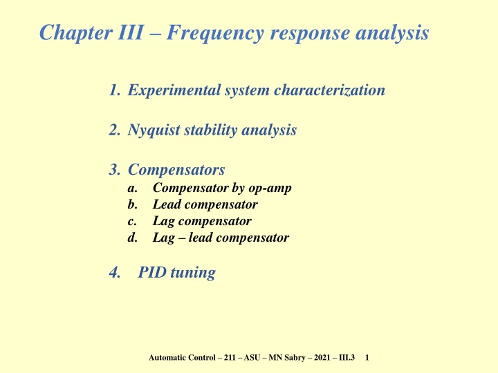
Chapter III Frequency response analysis 1. Experimental system characterization 2. Nyquist stability analysis 3. Compensators a. Compensator by op-amp b. Lead compensator c. Lag compensator d. Lag lead compensator 4. PID tuning Automatic Control 211 ASU MN Sabry 2021 III.3 1
Compensators using op-amps Performance parameters: stability, error, speed If only one parameter to modify: Adjust gain If more than one parameter to modify Use compensator (or PID see next section) E E z z z z Usually z3 = R3, z4 = R4 = o 2 4 1 3 i z2 z4 z1 z3 Ei + + Eo Adjust impedances z1, z2, R3, and R4 to get required behavior Automatic Control 211 ASU MN Sabry 2021 III.3 2
Lead compensator Better transient response ( n, ) Why Lead compensator? ( ) Reminder zi 1 R sC sC R s Ci ( ) = = = i + i i + z RC ( ) i i i i 1 1 z(s)= V(s)/I(s) R Time domain V=IR i i i E E zR = R zC = 1/sC zL = sL z z z z Ri z3 = R3, z4 = R4 = o 2 4 CdV/dt=I LdI/dt= V 1 3 i 1 2 + + + 1 1 E E 1 R R R R s s s = = = o 2 4 1 K G : attenuation factor R C + 1 s 1 3 2 i < 1 > 0 Lead compensator ( ) 2 ( ) + = 1 + + 2 2 G K G K 1 1 + G j 1 j = C C Re Im = C 2 2 2 2 2 1 + 1 K j R R R Automatic Control 211 ASU MN Sabry 2021 III.3 3
Lead compensator: frequency response + + 2 2 G K 1 1 |GC/KR| dB = C Re + 2 2 2 1 j = R G K C R + 1 j ( ) 2 + = 1 G K C Im 2 2 1 R Im Log( ) 1 1 2 max Re 1 + 1 1 =0 2 sin max= (1 ) / (1 + ) Log( ) ( )max= = (1 sin max) / (1 + sin max) Automatic Control 211 ASU MN Sabry 2021 III.3 4
Lead compensator: design Required: determine , , KR such as to satisfy error & stability margin + 1 s = G K C R + 1 s GT Algorithm + GC G Assume GT ~ G1 = KR G Select KR to satisfy error constraint or take KR high Get phase margin of G1 (@ = c): m1 If m1 < required margin m_req: put compensator phase c = m_req m1 + added Put c = max = sin 1 [(1 ) / (1 + )] Get new cross over frequency cnewof GC G: G G G K G K |G1| 0 5o 12o c cnew G1 get G K 1 m1 = = = = C C 1 G G 1 1 C R R R Put cnew = ( )max = 1/ get Verify performance of closed TF corresponding to: GT = GC G Automatic Control 211 ASU MN Sabry 2021 III.3 5
Example: lead compensator, I-start GT Find GC such that: Static vel. Err. Kv = 35 s 1 Phase margin m_req 60o Gain margin 10 dB 21 + Given: = G ( ) 3 s s + GC G Consider GT ~ G1 = KR G: |G1| ( ) = ( ) = = = lim 21 3 35 K sG K 0 0 v s T R 1/ 5 K R 5 21 s s Plot Bode plot of: = G ( ) 1 + 3 cnew=2.62Hz G1 get m = 180 163.35 = 16.65o c = 60 16.65 + 5 = 48.35o sin c = (1 )/(1+ ) =0.145 163.35o Get new cnew @ |G1| =1/ : cnew = 16.48 rad/s = 2.62 Hz Automatic Control 211 ASU MN Sabry 2021 III.3 6
Example: II-build and verify Put c = ( )max = 1/ get = Closed loop step response + 1 s = G K C R + 1 s Without compensation Verify performance of closed loop: Closed loop step response G G + = C G G Closed G 1 With compensation C Gain margin of GCG: Automatic Control 211 ASU MN Sabry 2021 III.3 7
Lag compensator Why Lag compensator? Better static response |GC/KC| dB + > 1 < 0 E E 1 s = = o G K C R + 1 s i + + 2 2 G K 1 1 Log( ) = C Re R R R R 2 2 2 2 4 R ( ) 2 1 3 + = 1 G K C Im 2 2 1 R = Im max Re Log( ) 1 1 2 ( )max= 1 1 + 2 sin max= ( 1) / ( + 1) Automatic Control 211 ASU MN Sabry 2021 III.3 8
Lag compensator design + Required: determine , , KR + 1 s = G K C R 1 s GT Algorithm + GC G Assume GT ~ G1 = KR G Select KR to satisfy error constraint or take KR high Draw Bode plot of G1 : Find the frequency new where: = ( m_req + added) Log 0 5o 12o new Select such that |GT| = 1 @ new Log Select such that 1/ < new/10 or higher if needed m_req + added Verify performance of closed TF corresponding to: GT = GC G Automatic Control 211 ASU MN Sabry 2021 III.3 9
Lag lead compensator Why Lag lead compensator? Lead improves transient performance (high ) Lag improves static performance (low ) Lag lead acts as Lag @ low and as lead @ high How to build a Lag lead compensator? Ri ( ) ( + ) + + + 1 1 1 + R R r C s C s R r C s R r C s = = i i i i i i Z ( ) ( ) i + 1 r i i i i i i ri Ci + + 1 + 1 + E E Z R Z R s s = = = o G K 2 4 1 2 Usually: = 1 C R 1 1 s s 1 3 1 2 i Lead Lag + R R R R r + r R ( ) = = = = + = ; 1; 1; ; whereK R r C r C 2 4 1 2 2 1 1 1 1 2 2 2 R r R r 1 3 1 1 2 Automatic Control 211 ASU MN Sabry 2021 III.3 10
Lag lead characteristics + + 1 + 1 + s s = |Gc /KR| in dB G K 1 2 C R 1 1 s s 1 2 Log = Design lag part as a lag compensator Design lead part as a lead compensator Keep 1 >> 2 1/( ) 1/( ) 1/ 1/ Im Log R Gc = = Re 1/ ( ) = 1/ ( ) Automatic Control 211 ASU MN Sabry 2021 III.3 11
Compensator selection Lead compensators are usually used to increase stability margins Lag compensators are usually used to improve static error If both Lag or lead can achieve objective, then Lead compensator will have a higher bandwidth Lead will also require higher capacity (size, energy ) Higher bandwidth improves settling time Lower bandwidth improves immunity to noise Lag lead compensator can be a good compromise to combine benefits of both Automatic Control 211 ASU MN Sabry 2021 III.3 12