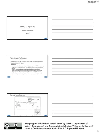
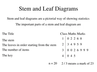
Understanding Entity-Relationship Diagrams (ERD)

An Entity-Relationship Diagram (ERD) is a vital data modeling technique for visualizing an information system's entities and their relationships. This graphical representation helps in database design by defining entities, analyzing interactions, and determining cardinality. Entities represent real-world items or concepts, akin to database tables, with attributes describing them. Relationships describe interactions between entities with cardinality specifying the associations. ERDs are crucial for developing high-level logical data models and creating good database designs.

Download Presentation

Please find below an Image/Link to download the presentation.
The content on the website is provided AS IS for your information and personal use only. It may not be sold, licensed, or shared on other websites without obtaining consent from the author. Download presentation by click this link. If you encounter any issues during the download, it is possible that the publisher has removed the file from their server.
E N D
Presentation Transcript
Chapter 4 Entity-Relationship Diagram (ERD)
An entity-relationship diagram (ERD) is : a data modeling technique that graphically illustrates an information system s entities and the relationships between those entities. a conceptual and representational model of data used to represent the entity framework infrastructure.
Steps involved in creating an ERD include: 1. Identifying and defining the entities. 2. Determining all interactions between the entities. 3. Analyzing the nature of interactions/determining the cardinality of the relationships. 4. Creating the ERD.
crucial to creating a good database design. used as a high-level logical data model, which is useful in developing a conceptual design for databases.
Entity An entity is a real-world item or concept that exists on its own. Entities are equivalent to database tables in a relational database, with each row of the table representing an instance of that entity.
Attribute An attribute of an entity is a particular property that describes the entity. Relationship A relationship is the association that describes the interaction between entities. Cardinality in the context of ERD, is the number of instances of one entity that can, or must, be associated with each instance of another entity. In general, there may be one-to-one, one-to-many, relationships. or many-to-many
Employee Entity Department Entity Department Attribute : Employee Attribute : department number name employee number name Department number department department number name 1 Employee employee number name department number M
2 Components of E-R Diagram Entity relational diagram (ER Diagram) is used to represent the requirement analysis at the conceptual design stage. the database is designed from the ERD or ERD is converted to the database. Each entity in the ERD corresponds to a table in the database. The attributes of any an entity correspond to field of a table. The ERD is converted to the database.
The elements of an ERD are: 1. ENTITIES Entities are objects or concepts that represent important data. They are typically nouns (customer, supervisor, location, or promotion).
Strong entities exist independently from other entity types. They always possess one or more attributes that uniquely occurrence of the entity. Weak entities depend on some other entity type. They don't possess unique attributes (also known as a primary key) and have no meaning in the diagram without depending on another entity. This other entity is known as the owner. Associative entities are entities that associate the instances of one or more entity types. They also contain attributes that are unique to the relationship between those entity instances. distinguish each
Entity Weak Entity Associative Entity
2. RELATIONSHIPS o Relationships are meaningful associations between or among entities. o They are usually verbs, e.g. assign, associate, or track. o A relationship provides useful information that could not be discerned with just the entity types.
Weak relationships, or identifying relationships, are connections that exist between a weak entity type and its owner. Ternary Relationship,Relationship of degree three.
Weak Relationship Relationship
3. ATTRIBUTES Attributes are characteristics of an entity. Attribute
Multivalued attributes are those that are capable of taking on more than one value. . Multivalued Attributes
Derived attributes are attributes whose value can be calculated from related attribute values. Derived Attributes
Composite attributes are represented by ellipses that are connected with an ellipse. they are further divided in a tree like structure. Every node is then connected to its attribute Attribute composite Attribute Attribute
Key attribute represents the main characteristic of an Entity. It is used to represent Primary key. Ellipse with underlying lines represent Key Attribute. Key Attribute
3. Binary Relationship and Cardinality Binary relationship :A relationship where two entities are participating. Cardinality is the number of instance of an entity from a relation that can be associated with the relation. One-to-one When only one instance of an entity is associated with the relationship, it is marked as '1:1'. The following image reflects that only one instance of each entity should be associated with the relationship. It depicts one-to- one relationship.
The following image reflects that only one instance of each entity should be associated with the relationship. It depicts one-to-one relationship. 1 1 Entity Relationship Entity
One-to-many When more than one instance of an entity is associated with a relationship, it is marked as '1:N'. The following image reflects that only one instance of entity on the left and more than one instance of an entity on the right can be associated with the relationship. It depicts one-to-many relationship. N 1 Entity Relationship Entity
Many-to-one When more than one instance of entity is associated with the relationship, it is marked as 'N:1'. The following image reflects that more than one instance of an entity on the left and only one instance of an entity on the right can be associated with the relationship. It depicts many- to-one relationship. 1 N Entity Relationship Entity
Many-to-many The following image reflects that more than one instance of an entity on the left and more than one instance of an entity on the right can be associated with the relationship. It depicts many-to-many relationship. N N Entity Relationship Entity
Customer-street loan-number Customer-name amount Customer-city Customer-id customer borrower loan Figure 4.1 E-R diagram corresponding to customers and loans
The relationship set borrower may be many-to-many, one-to-many, many-to-one, or one-to-one. To distinguish among these types, we draw either a directed line ( )or an undirected line ( ) between the relationship set and the entity set in question.
A directed line () from the relationship set borrower to the entity set loan specifies that borrower is either a one-to-one or many-to-one relationship set, from customer to loan,borrower cannot be a many-to- many or a one-to-many relationship set from customer to loan Customer-street loan-number Customer-name amount Customer-city Customer-id 1 customer borrower loan
An undirected line () from the relationship set borrower to the entity set loan specifies that borrower is either a many-to-many or one-to-many relationship set from customer to loan. Customer-street loan-number Customer-name amount Customer-city Customer-id N N customer borrower loan
If the relationship set borrower were one-to-many, from customer to loan, then the line from borrower to customer would be directed, with an arrow pointingto the customer entity set Customer-street loan-number Customer-name amount Customer-city Customer-id N 1 customer borrower loan
if the relationship set borrower were many-to-one from customer to loan, then the line from borrower to loan would have an arrow pointing to the loan entity set Customer-street loan-number Customer-name amount Customer-city Customer-id 1 N customer borrower loan
Finally, if the relationship set borrower were one-to- one, then both lines from borrower would have arrows Customer-street loan-number Customer-name amount Customer-city Customer-id 1 1 customer borrower loan
Customer-id middle-name Customer-id Customer-id Last- name First- name name street city address Customer-id state customer zip-code Phone-number age date-of-birth
level title branch-city job street employee-name branch-name assets city employee-id employee work-on branch
5. Reduction of an E-R Schema to Tables We can represent a database that conforms to an E-R database schema by a collection of tables. For each entity set and for each relationship set in the database, there is a unique table to which we assign the name of the corresponding entity set or relationship set. Each table has multiple columns, each of which has a unique name.
Both the E-R model and the relational-database model are: abstract, logical representations of real-world enterprises. Because the two models employ similar design principles, we can convert an E-R design into a relational design. Converting a database representation from an E-R diagram to a table format is the way we arrive at a relational-database design from an E-R diagram.
Although important differences exist between a relation and a table, informally, a relation can be considered to be a table of values. The constraints specified in an E-R diagram, such as primary keys and cardinality constraints, are mapped to constraints on the tables generated from the E-R diagram.
Example : There is an entity: customer-schema=(customer-id,name,address,city-state-ZIP,discount) 1.Transforming an entity to a relation E/R Diagram. 2.Transforming an entity to a relation relational .
Address City-state-zip name Discount Customer-id customer Customer ID Name Address City State-Zip Discount 1273 Contemporary Designs 123 Oak St. Austin,TX2888 5% 6390 Casual Comer 18 Hoosier Dr. Bloomington ,IN5482 3%


 is :")


 from the relationship set")
 from the relationship set")