Understanding Special Purpose Diodes in Electronics
Explore the Zener diode and its characteristics for voltage regulation. Learn about the Varactor diode and its operation. Delve into the features, operation, and applications of LEDs, quantum dots, and photodiodes in electronics.

Download Presentation

Please find below an Image/Link to download the presentation.
The content on the website is provided AS IS for your information and personal use only. It may not be sold, licensed, or shared on other websites without obtaining consent from the author. Download presentation by click this link. If you encounter any issues during the download, it is possible that the publisher has removed the file from their server.
E N D
Presentation Transcript
Basic Electronics Chapter 3: Special Purpose Diodes 3 1 The Zener Diode 3 2 Zener Diode Applications 3 3 The Varactor Diode 3 4 Optical Diodes
Describe the characteristics of a zener diode and analyze its operation Apply a zener diode in voltage regulation Describe the varactor diode characteristic and analyze its operation Discuss the characteristics, operation, and applications of LEDs, quantum dots, and photodiodes
Zener diode Zener breakdown Varactor Light-emitting diode (LED) Photodiode
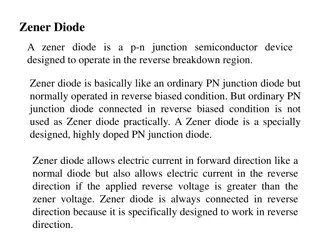
31 THE ZENER DIODE A zener diode is a silicon pn junction device that is designed for operation in the reverse-breakdown region A major application for zener diodes is as a type of voltage regulator for providing stable reference voltages for use in power supplies, voltmeters, and other instruments.
Zener Breakdown Zener diodes are designed to operate in reverse breakdown. Two types of reverse breakdown in a zener diode are avalanche and zener. The avalanche effect occurs in both rectifier and zener diodes at a sufficiently high reverse voltage. Zener breakdown occurs in a zener diode at low reverse voltages. A zener diode is heavily doped to reduce the breakdown voltage. This causes a very thin depletion region.
Zener Equivalent Circuits Figure 3 4 shows the ideal model (first approximation) of a zener diode in reverse breakdown and its ideal characteristic curve. It has a constant voltage drop equal to the nominal zener voltage. This constant voltage drop across the zener diode produced by reverse breakdown is represented by a dc voltage symbol even though the zener diode does not produce a voltage.
Figure 35(a) represents the practical model (second approximation) of a zener diode, where the zener impedance (resistance), ZZ, is included.
Temperature Coefficient The temperature coefficient specifies the percent change in zener voltage for each degree Celsius change in temperature where VZ is the nominal zener voltage at the reference temperature,TC is the temperature coefficient, and is the change in temperature from the reference temperature. A positive TC means that the zener voltage increases with an increase in temperature or decreases with a decrease in temperature. A negative TC means that the zener voltage decreases with an increase in temperature or increases with a decrease in temperature.
Zener Power Dissipation and Derating Zener diodes are specified to operate at a maximum power called the maximum dc power dissipation, PD(max). PD = VZ x IZ Power Derating :The maximum power dissipation of a zener diode is typically specified for temperatures at or below a certain value . Above the specified temperature, the maximum power dissipation is reduced according to a derating factor. The derating factor is expressed in The maximum derated power can be determined with the following formula:
32 ZENER DIODE APPLICATIONS Zener Regulation with a Variable Input Voltage
33 THE VARACTOR DIODE A varactor is a diode that always operates in reverse bias and is doped to maximize the capacitance of the depletion region. The depletion region acts as a capacitor dielectric, The p and n regions are conductive and act as the capacitor plates. A major application of varactors is in tuning circuits. For example, VHF, UHF, and satellite receivers utilize varactors. Varactors are also used in cellular communications
34 OPTICAL DIODES Three types of optoelectronic devices are introduced: the light-emitting diode, quantum dots, and the photodiode. 3-4-1 The Light-Emitting Diode (LED) The basic operation of the light-emitting diode (LED) is as follows. When the device is forward-biased, electrons cross the pn junction from the n-type material and recombine with holes in the p-type material. The difference in energy between the electrons and the holes corresponds to the energy of visible light. When recombination takes place, the recombining electrons release energy in the form of photons. The emitted light tends to be monochromatic (one color) that depends on the band gap (and other factors).
LED Semiconductor Materials The semiconductor gallium arsenide (GaAs) was used in early LEDs and emits IR radiation, which is invisible. The first visible red LEDs were produced using gallium arsenide phosphide (GaAsP) on a GaAs substrate. The efficiency was increased using a gallium phosphide (GaP) substrate, resulting in brighter red LEDs and also allowing orange LEDs.
Applications of LEDs Standard LEDs are used for indicator lamps and readout displays on a wide variety of instruments, ranging from consumer appliances to scientific apparatus. A common type of display device using LEDs is the seven-segment display.
3-4-2 Quantum Dots Quantum dots are a form of nanocrystals that are made from semiconductor material such as silicon, germanium, cadmium sulfide, cadmium selenide, and indium phosphide. Quantum dots are only 1 nm to 12 nm in diameter. There are other promising applications, particularly in medical applications. Water-soluble quantum dots are used as a biochemical luminescent marker for cellular imaging and medical research. Research is also being done on quantum dots as the basic device units for information processing by manipulating two energy levels within the quantum dot.
3-4-3 Photodiode The photodiode is a device that operates in reverse bias, as shown in Figure 3 44(a), where I is the reverse light current. The photodiode has a small transparent window that allows light to strike the pn junction. Some typical photodiodes are shown in Figure 3 44(b). An alternate photodiode symbol is shown in Figure 3 44(c).
A photodiode differs from a rectifier diode in that when its pn junction is exposed to light, the reverse current increases with the light intensity. When there is no incident light, the reverse current, is almost negligible and is called the dark current


 represents the practical model (second")
 represents the practical model (second")