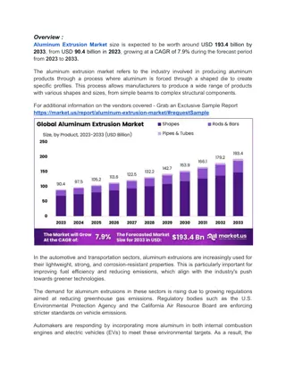
Optimizing Aluminum Smelting Operation Parameters for Energy Efficiency
The current efficiency of an aluminum smelting operation is at 94% with excess AlF3 superheat, operating at low energy consumption. However, to comply with a power cap, the manager wants to reduce the voltage by 0.2V. This voltage decrease leads to a heat balance problem, necessitating actions such as increasing anode cover size and adjusting the anode-to-cathode distance. Potential issues include unstable pots, freezing pots, and current efficiency loss if not addressed promptly.

Download Presentation

Please find below an Image/Link to download the presentation.
The content on the website is provided AS IS for your information and personal use only. It may not be sold, licensed, or shared on other websites without obtaining consent from the author. Download presentation by click this link. If you encounter any issues during the download, it is possible that the publisher has removed the file from their server.
E N D
Presentation Transcript
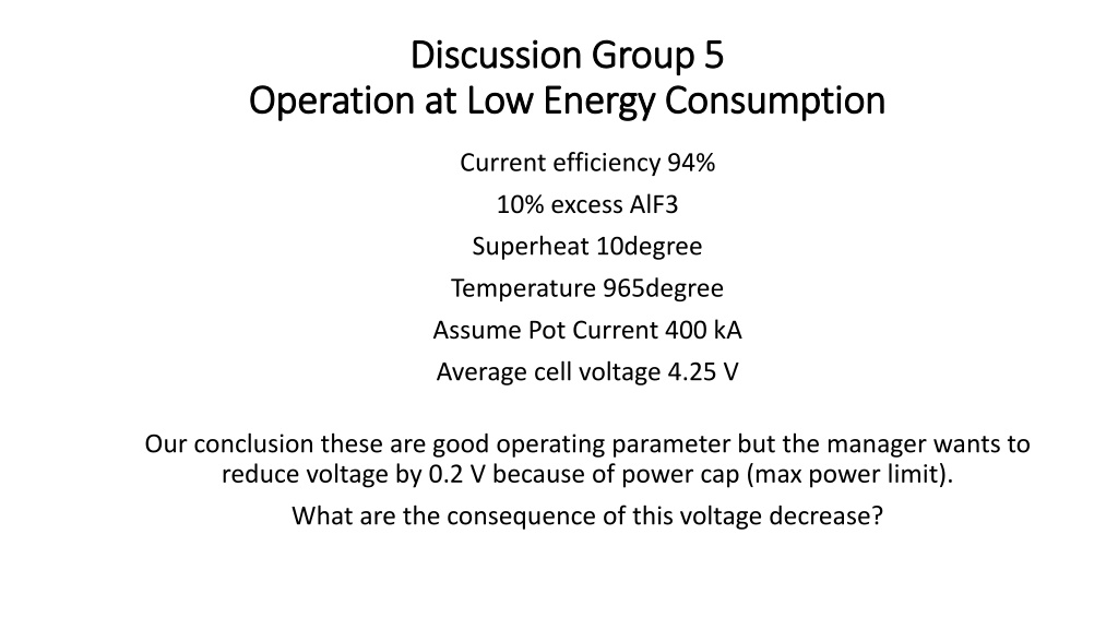
Discussion Group 5 Discussion Group 5 Operation at Low Energy Consumption Operation at Low Energy Consumption Current efficiency 94% 10% excess AlF3 Superheat 10degree Temperature 965degree Assume Pot Current 400 kA Average cell voltage 4.25 V Our conclusion these are good operating parameter but the manager wants to reduce voltage by 0.2 V because of power cap (max power limit). What are the consequence of this voltage decrease?
Current = 400 kA Voltage = 4.05 V With this low voltage, we have heat balance problem (not enough heat generation). Internal heat = (Vcell Vexternal Val) x kA Orignal internal heat = (4.25 V 0.3 V 2.05 V) x 400 kA New internal heat = (4.05 V 0.3 V 2.05 V) x 400 kA Difference of internal heat = 0.2 V x 400 kA = 80 kW We need to conserve 80 kW in the pot.
Action to be taken Action to be taken 1. Increase anode cover from 6 cm (now) to 20 cm (future). 1 cm anode cover equal to 6 kW. 14 cm x 6 kW/cm = 84 kW, (this is sufficient). 2. Anode cover is 14 cm now increase to 20 cm. In this case 5 kW/cm anode cover, in other words, 6 cm x 5kW/cm = 30 kW, we need to conserve 50 kW more. a) Decrease metal height by 2 cm, this give 8 kW. b) We reduce pot shell ventilation (put heat loss barriers on the side and end of the shell). c) We will operate with 8 degree Celsius superheat, this will increase side ledge fitness and will reduce heat loss.
Anode to Cathode Distance Anode to Cathode Distance Reduced Voltage of 0.2 V means that we are squeezing ACD how much? We determine that 40 mV bath voltage drop correspond to 1 mm of ACD, altogether we squeeze ACD by 5 mm (200 mV). Will this decrease Current Efficiency?? Plant engineers believe that the operation now is on flat part of current efficiency VS ACD (show with arrow on next slide).
Current Efficiency VS ACD CE% Low voltage Operation is here 95 94 93 92 Operation now is here 91 90 89 88 0 1 2 3 4 5 6 ACD (cm) The low voltage ACD is maybe on the boundary of current efficiency decrease.
Indicators of problems Indicators of problems Pots become unstable (will be confirmed in 1 to 2 weeks). Pots are freezing (difficult to set anodes, anode rods bent particularly in the corner, confirmed in 2 to 3 weeks). Current efficiency loss (time to confirm = 3 months). If current efficiency decreases, heat balance is easier because 1 % of current efficiency loss generates 6 kW, but the manager will not like this.